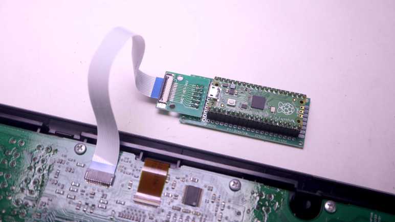
I bought some FPC (flexible printed circuit) cables and connector breakout boards from Amazon vendors so I no longer have to solder wires directly to my salvaged Canon Pixma MX340 multi-function inkjet control panel. The first FPC breakout board went on a perforated prototype board to host a Raspberry Pi Pico. Up until this point I had been using Adafruit’s KB2040 board. But since they’re both based on RP2040 chip and have CircuitPython support, switching my code to run on a Pi Pico is a minor task of changing over a few pin names.
Soldering to the FPC breakout board with its 0.1″ (~2.54mm) pitch was far easier than the 1.0mm pitch of soldering directly to the control panel. Which meant I finally got around to connecting five wires that were previously not connected:
- 5 volt DC wire to supply WiFi LED
- LED+ for Power LED, in series with an 100 ohm current-limiting resistor already on board.
- LED+ for Alarm LED, also with resistor.
- Power button that is pulled to ground when pressed.
- Stop button that is pulled to ground when pressed.
My CircuitPython code had provision to set the appropriate bit flags to manipulate the WiFi LED, but I hadn’t tested it until this point due to lack of +5V power. I was happy to see it worked, but I doubt I would find a use for it. As it originally shined into a clear plastic light guide and thus pointed in an opposite direction from the rest of the control panel.
And I hadn’t dealt with the remaining four wires at all, as I considered the two direct-wired buttons and two direct-wired LEDs fairly standard microcontroller fare. And indeed, there were no surprises after I declared two CircuitPython digitalio pins for those LEDs and a keypad instance to read (and debounce) those two buttons. All worked as expected on the first try.
I updated my test app to toggle power LED upon presses to the power button, and the same for alarm LED and the stop button. The “In Use/Memory” and WiFi LEDs blink their own separate heartbeat patterns. And the LCD displays status of key matrix scan code activity: every time one of the K13988-scanned button is pressed, its name is displayed on the LCD. It makes for a simple demo to prove I have complete control over all electronic functionality of this salvaged control panel. Now this control panel waits for a project that could put it to good use but while it’s waiting, I went ahead with a project that puts it to silly fun use.
