Window Shopping: NASA Perseverance Rover 3D Print Static Model

After finishing a model of Mars rover Curiosity, the obvious question is: did NASA release a 3D print static model of its successor Perseverance? And the answer is yes! Curiously, the web site page points to a 3D file suitable for graphics rendering, not for 3D printing. But poking around the GitHub repository revealed there’s a “M2020” 3D print model. (Before receiving its name, Perseverance was called Mars 2020.)

Armed with my recent experience, I looked over the files for this printable rover. First the good news: the rocker-bogie suspension is represented in much higher fidelity on this model. The full rocker bogie geometry is represented, including a differential bar that is designed for some bent paperclips to serve as critical linkages. The wheel tracks appear to be correct with the center pair of wheels having wider tracks than the front and rear pairs. And the geometry is more accurate, no weird right angle bends as concession to ease of printing.

The lack of concession to ease of printing is also the bad news. Unlike the previous model, none of the geometry has been modified to fit flat on a print bed. Printing this model will require, at a minimum, printing with supports which is always problematic. Dual-material printer with dissolvable supports should make such designs easy to print, but I don’t have one of those.

Another change from the previous model is that this one doesn’t use snap-together construction. Parts are designed to be glued together instead. It also means these files assume a much higher printing precision, since superglue requires a much tighter fit than snap-together construction.

If I saw these traits on a Thingiverse item, I would be skeptical that the model is even buildable. That site is littered with too many things that are obviously impossible, merely the dream someone created in CAD and never test printed.

But this one appears to be real, since among the STL files is a picture of this rover design that has been built. Looking over the print quality of its parts, it was obviously printed at high detail quality on a good printer. Likely better than mine! I think I’ll hold off printing this rover design for the moment. Maybe later, when I have a well dialed-in printer that I can trust to meet precise tolerance requirements. In the meantime, I can admire the Perseverance 3D Model released by NASA that lives strictly in the digital realm.

Built NASA’s Curiosity Rover 3D Printed Static Model

I’ve completed assembly of a 3D-printed static display model, released by NASA, of Mars rover Curiosity. It had a lot of details that were demanding when printed in PETG. In hindsight, I should have printed with PLA for fewer printing problems like stringing and overhangs. It is only a display model, it’ll just sit on a shelf and not stand out in the sun as Sawppy has done (and suffered for it.) Better dimensional accuracy with cleaner printing PLA would also help make the snap-together construction more effective. PETG is more ductile and so there wasn’t a “click” to announce successful assembly.

The demanding details were fitting for a static display model. Unlike its smaller sibling, this one is even poseable with corner wheels that steer and a robot arm that can articulate through the same degrees of freedom as the robot arm of the real thing.

With its emphasis on appearance, I was disappointed at the representation of my favorite feature of NASA JPL’s Mars Rovers: their rocker-bogie suspension. The first complaint is cosmetic: this model placed all three pair of wheels with the same track (distance between left and right wheels.) Curiosity’s front and rear wheel pairs actually have a narrower track than the middle pair, which I speculated was done that way so the suspension can fold up for flight. While a static model does not need to fold up for flight, it should at least accurately represent the layout.

The next complaint is a combination of cosmetic and functional: the suspension rockers do not articulate. Their angle is fixed relative to the body. On Curiosity, the left and right rockers are connected via the differential bar which keeps the two rockers in sync with complementary movement: if one moves up, the other moves down the same amount. But on this model, the differential is a surface feature and not a functional one, without connection to the suspension rocker.

On the upside, at least this model has articulation for suspension bogies. This was also missing from its smaller sibling. With articulating bogies, this rover model can at least pretend to handle rough terrain capability even if it lacks full rocker-bogie capability. In this picture, the middle wheel is raised by a piece of 3D-printed plastic I had on hand.

And finally, the suspension arms leading up to corner steering wheels have right-angle bends that are not an accurate representation of Curiosity’s suspension. I suspect this was done as a compromise to make these parts 3D-printable without supports, but it further reduces fidelity of this model.

There are several additional print problems with this first draft. If I were excited about this model I would reprint in PLA to see if it improves as expected. But given my lack of enthusiasm about representation of rocker-bogie suspension, I am content to stop here and look around for the next project.

NASA’s Curiosity Rover Model Print Cleanup and Assembly

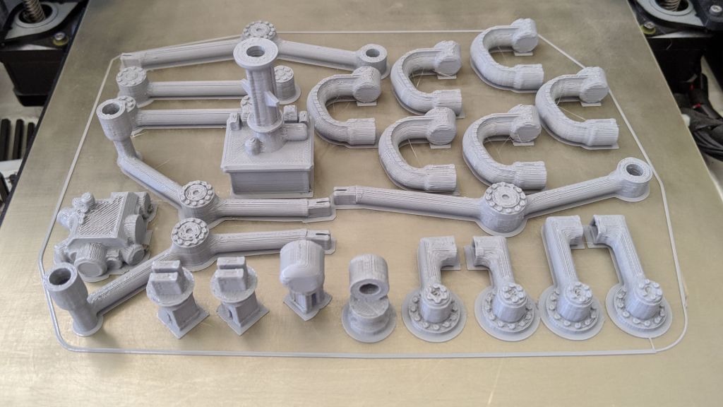
NASA published a 3D printable static display model for Curiosity rover, and one of the things they offered to make printing easier are STL files that have already laid out many parts so they can be printed all at once. The upside is a lot less work on setup and less time tending to the printer. The downside is that if one part fails, it dooms the entire print.

The rover suspension parts are all in a single large multipart print. The real Curiosity rover suspension structure is cylindrical, and this model tries to maintain that shape, meaning there’s very little surface area contacting the print bed at the bottom of the cylinder. In the first few failed attempts, one of the suspension parts (and never the same one twice) would pop free from the print bed and wreck havoc.

To work around this, I told MatterControl to add a brim on all parts to increase surface contact area. It allowed the print to complete, but now I have to cut all those brims off before I could proceed to assembly.

I started by cleaning up the wheel hubs and pressing them into wheels.

Following my tradition of rover building, I proceeded to build a rover wheel on a stick.

Which quickly led to a rocker-bogie assembly for one side of the rover.

Unfortunately, the rocker does not articulate on this model. Its angle relative to the body is fixed. So this particular portion of the model is no more functional than the smaller version. However, the bogie does articulate, and all four of the corner wheels can steer.

Having built one side, it was easy to build the mirror side and put everything together. I noticed I had two extra steering brackets left over. Reviewing the large multipart print, I now notice there are six steering brackets even though only four rover wheels could steer. I shrug and move on.

Assembly of the robot arm was straightforward following the directions, leaving rover head installation as the final step. The static model is complete and I can admire it in its entirety.

3D Printing NASA’s Curiosity Rover Model

I decided to build the 3D printed Curiosity rover model released by NASA, and ran into some problems with print bed adhesion. Whoever designed this model had a 3D printer with better print bed adhesion than mine. My first few printed parts would lift from my print bed.

Some of this is unavoidable, the natural orientation of some parts dictate minimal surface area. The wheels, for example, have to sit with their narrow side edges on the bed because that is the only flat side. Fortunately wheels are round and produced minimal stress.

In contrast, the body of the rover is a large rectangular solid with sharp corners. This is a recipe for lifts and they released the STL files with some pre-generated brims to help the corners stick. Unfortunately that was not enough for me, because some of the corners still lifted off the print surface. Fortunately this was only a minor cosmetic issue, since the bottom does not need to be absolutely flat to mesh with any other part.

Another cosmetic issue is the radiothermal generator at the back, which ramped up more aggressively than my Pulse XE revision D printer could handle with PETG. Fortunately this is a bottom-facing surface and shouldn’t be too much of a detraction.

The wheel spokes were the most problematic with their fine detail requiring a lot of filament retraction as the print head moves from one tiny feature to another. In my experience, retraction-heavy prints work much better in PLA than PETG, in hindsight that’s what I should have used.

An interesting nod to convenience is that, in addition to publishing STL for individual parts, the creator of this project also included STL files with many parts laid out to be printed all at once. The upside is that there’s a lot less overhead. The downside is that failures can be troublesome.

NASA’s 3D Printable Curiosity Rover

When I take Sawppy out for some publicity, people frequently ask about the 3D printable Curiosity rover static model released by NASA. Some mistakenly thought Sawppy was the NASA-released design, others wanted to know how the rovers compared. I couldn’t answer the latter because I never printed the NASA rover, to the surprise of some, so I thought I should do it at least once.

NASA’s 3D printing resources page for a printable Curiosity points to a GitHub directory that actually has two printable models. I’ve seen the smaller one at a MatterHackers event, printed by another attendee who left her little rover on Sawppy’s table to keep my rover company.

The small model has limited articulation. All six wheels can roll, but cannot steer and it could only sit on a flat surface because its rocker-bogie suspension joints are fixed. I also noticed the robot arm joint articulation doesn’t match that of the real rover’s. Still, it is undeniably a representation of Curiosity and a cute little model.

Since I’ve seen the little one, I decided to skip it and try building the larger one. “Large” is relative, of course, it would still be much smaller than Sawppy. Another important difference is that it is an unmotorized static display model, which is actually the main reason I had not tried to build it. I wanted a rover that moved!

But I’m glad I’ve built it, because it was a good study into the different compromises this model made for the sake of being 3D printing friendly.

Quick Print Xbox One X Vertical Stand

Reorganizing my video game console area, I’ve decided to reorient my Xbox One X so it stands vertically to take up less table area. The console was designed to handle this scenario for the most part. There is even a designed hint on which side of the console to use: only one of the two sides is flat enough for standing. However, it is not quite as simple as turning the console on its side, because there is an open cooling vent grille on that side.

Side of Xbox One X showing cooling vents

In order to elevate the console so air can still flow through those holes, a stand is needed. There are official stands available… but where’s the fun in that? I could 3D print something and there are several stands already on Thingiverse. But I didn’t think that was any fun, either. I much rather design and print my own, but how will my contribution be different? I focused on simplicity and print time. My design should be faster to print than the others.

I focused on designing while keeping the print path in mind. It is one continuous curve that can be printed with only perimeters. No infill, no top layer, no bottom layer, no retractions. And no supports, either.

MatterControl slicer showing the design sliced as continuous curve.

I will need to print two of them.

Two copies of the design were printed, one for front and one for back.

The installation position doesn’t have to be exact, since the grille doesn’t seem to be covering anything in a particular pattern that would require that I keep the nearby holes clear. I think it should be OK to flow around these feet.

The two stands installed on Xbox One X, covering minimal cooling vent area.

The single loop design means the stand is not completely rigid but slightly flexible. The upside of this flexibility is that it will sit nicely on surfaces that are not perfectly flat. The downside of the flexibility is that the console may wobble a bit if bumped. Such is the tradeoff.

Xbox One X sitting on vertical stand.

Now my Xbox One X can stand vertically without completely blocking its cooling intakes. If someone wants to tinker with this design, the Onshape CAD file is a public document here. If someone wants to use the design as-is, it has been published to Thingiverse.

Otvinta 3D Printed Hypocycloid Drive Model

Before I dive headfirst into designing a project around hypocycloid drives, I thought I should first try the low-effort test of printing up an existing design to see how it works. If it does, I get to see a printed hypocycloid drive in action. If it fails, I have data points on how to (and maybe not to) 3D print a hypocycloid drive.

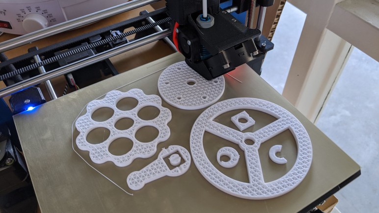
Lucky for me, the very same site hosting a hypocycloid gear calculator also has a ready-to-print set of STL files for a 3D-printable hypocycloid speed reducer model. It looks like a nifty little hand-cranked demonstrator, so I fired up my 3D printer to print one of each STL. I noticed a lot of little artifacts on component mating surfaces. I was eager to see it in action, so I did only minimal cleanup with a blade before proceeding.

Hypocycloid demo model breakaway handle

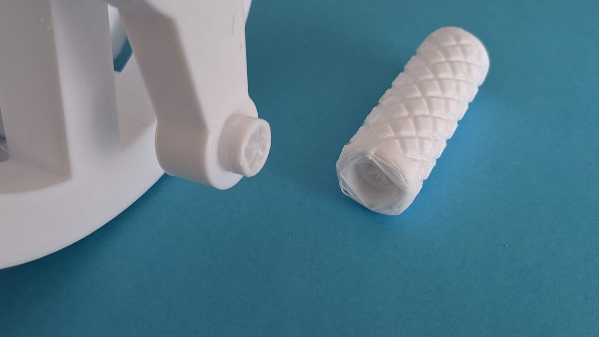
One instance of theory not meeting reality was in the crank handle. The geometry was designed such that the outer grip could rotate around a center shaft. They are printed in a single piece but there’s a gap allowing the outer trip to break free and rotate about the center shaft. I’ve done this sort of designed breakaway before, but this one didn’t work well for me and it broke off at the wrong place, on the inner shaft instead of the outer handle. Oops.

Hypocycloid demo model big gap

Upon assembly I noticed a big gap, and some parts were falling out of place. It didn’t take long before I realized there were two components (a cam and a disk) where I needed to print a second unit, rather than printing just one as I had done.

Hypocycloid demo model broken

Once both disks were in place the overall system friction went up dramatically. Optimistically thinking they’re just small bumps that can wear down with a few cycles, I tried to power past the friction points. But instead of breaking through sticky portions, I broke the input drive shaft.

I asked to print another drive shaft on a more precise 3D printer. While it was printing, the device was taken apart to better clean up surface artifacts. Round 2 was far more successful, making a fun toy and sufficiently prove the concept for future experimentation.

Hypocycloid Drive Calculator by Otvinta

The best part of maker/hacker gatherings is the opportunity to meet and chat with people who introduce me to ideas and resources. At Sparklecon 2020 I met Allen Phuong who saw Sawppy roaming around and wanted to learn more. Sadly he had missed my Sawppy presentation because he was busy participating in the battle bot competition taking place at the same time, but I gave him an abbreviated version and we talked about many projects on our respective to-do lists, robotic and more.

Allen got me interested in hypocycloid gears again. It was something I briefly examined while looking for ways to build a gearbox to obtain low speed and high torque but without the backlash present in typical gearboxes. Right now the standard solution in robotics is the harmonic drive, which is an expensive solution that has specific requirements on the material used to build the flexible spline. 3D printer plastic does not meet all the requirements and hence 3D-printed harmonic drives always involve trade-offs that made me less interested.

Cycloidal drives do not have a flexible component with strict material behavior requirements, all parts remain rigid while in operation. For (near) zero backlash operation, however, it requires high dimensional accuracy. I dismissed it for this reason as 3D printing is not very precise. However, Allen asserted that 3D printers can reach the required levels so maybe it’s worth a second look. And even if I can’t get my 3D printer to meet my dimensional accuracy goals, I now have access to a few tools that I didn’t have before. Ranging from a laser cutter, to my project CNC mill, to a resin printer. All capable of far higher accuracy than my 3D printer.

There are a few tools available online to help generate profiles based on parameters I specify. Allen pointed me to the Hypocycloid Gear Calculator on Otvinta, which looks like a worthwhile starting point. The author of this site has decided to focus on Blender as the 3D tool, so if I want to make use of the results, I’ll have to learn how to translate it into Onshape or Fusion 360. But first, I can get a taste via a ready-made project.

Hex Wrench Holder And Wire Clip For Gantry Extrusion

The first project for designing accessories to mount on the extrusion beam, a holder for ER11 collets, turned out well enough I wanted to continue. Apply some of the lessons learned to create more nice-to-have accessories for the CNC project.

One accessory is a holder for a 5mm hex wrench. This is the size used by the fasteners bolting our gantry’s extrusion beams together. There are a set of four bolts, two on the left and two on the right, that we loosen to adjust the height of the gantry. Lowering the gantry lets the cutter cut through our work surface to cut holes for threaded inserts, raising the gantry gives us more Z travel for the work piece. Or we might deliberately trade off Z travel to use a shorter and more rigid gantry for more challenging pieces. We’re not sure what the viable combinations are, but we do know we’ll need this wrench handy for experimentation.

The other accessory is a wire management clip. Wiring is a perpetual challenge on this project, from finding appropriate component placement to isolating electrical noise. I’m sure electrical challenges will continue to vex us as we proceed. We’ll figure out the problems one by one as we go, but one thing is for sure, we’ll need a lot of ways to route wires and keep them in place, hence the clips.

Unlike the previous accessories, the wiring clip may be mounted in any orientation. To hold themselves in place, each clip will require additional holding force. To get this force, they are printed slightly more open than their installed configuration. Installation would then require compressing the ring and this tension in the plastic will provide friction against extrusion rail to hold it in place. And while I’m not entirely sure it will be necessary, I added a small flap to keep the wire from sliding out of the ring into the rail slot.

There will be more accessories along the lines of what’s been printed so far, but I’m eager to get back to the primary exploration of cutting material.

Collet Holder Clamps To Extrusion

While I was in Onshape CAD designing our goose neck work holding clamps, I also tackled a few other to-do items on the 3D-printable accessory list. The top of the list was building a way to keep extra collets accessible on the machine. Our CNC spindle came packaged with a 1/8″ ER11 collet, which we swapped out for a 1/4″ collet when we wanted a stouter cutter. We didn’t have a good place to keep the temporarily unused 1/8″ collet and, rolling around on the tabletop, we were constantly at risk of losing it.

I thought it was a good project to practice designing plastic’s flexibility to my advantage instead of constantly seeing it as a disadvantage. I’ve had several projects along these lines before, but my interest was renewed by Amy Qian’s demo board she brought to show off at Supercon.

There are two ways I wanted to apply this concept. First, I wanted a holding mechanism that can snap into an extrusion rail and stay there without use of tools or fasteners. Second, I wanted a way to hold the collet so that it is held securely by default (not fall out or be dropped easily) but can be removed easily on demand. Again without tools or fasteners.

Here is the first draft of a flexible clip for installation into extrusion beam, this design was too flexible and fell out of the extrusion rail easily. More iterations followed, hunting for the most secure hold possible while still making it possible to insert into the rail.

Extrusion slot clip

Separately, I started designing a flexible cover for the collet. The test piece for each mechanism evolved separately until I was happy with both designs, then they were integrated into a single piece incorporating both mechanisms.

Collet holder evolution

With the success of this holder, I took the lessons of a flexible extrusion beam mount and applied the concept to a few additional 3D printed accessories.

3D Printed Goose Neck Clamps For Work Holding

Once we have metal threads securely inserted into our MDF work surface, we could bolt on clamps to hold our work pieces. These clamps are 3D printed because we fully recognize our CNC beginner status and, while we’ll do our best to avoid crashing cutting bits into fixtures, it’s realistic to plan for the probability that crashes will occur despite our efforts. If we use commodity metal clamps and our carbide cutting tool makes contact it will break our tool. But if our carbide tool contacts a piece of 3D printed plastic it might survive our mistake. We have the luxury of this provision because we’re starting easy with scraps of MDF, which requires less forces to hold and to cut than cutting metal.

Clamp evolution

We started by copying standard step clamps. We weren’t sure if the steps could be accurately replicated with 3D printed plastic so it was worth a bit of experimentation to find out. They look very promising but we probably won’t use them, because the reason step clamps exist is to have a few set of them that can adjust to various sized work pieces. 3D printing gives us the flexibility to print project-specific fixtures that don’t have to compromise for flexibility. This advantage can make up a tiny bit of deficiency inherent in using plastic instead of metal. Hence the second iteration: a single piece clamp shaped like an L designed specifically for the thickness of our test piece of MDF.

Once that was printed and eyeballed on the work table, we moved on to the third iteration: a low profile goose neck clamp tailored for the height of our scrap MDF. Low profile design reduces chance of cutter collision, and it allows us to use shorter and stouter bolts to fasten them to the table. This is what we will use for our first real cutting experiments, alongside other 3D-printed accessories for our CNC project like a collet holder.

Threaded Insert Alignment Tool

We now have a small G-code program that we can call upon to cut holes for self-tapping threaded inserts. We’ll cut them as needed for work fixtures on our CNC work table. However, cutting the hole is only part of the process, we had to install the metal insert as well. In order for the resulting threaded hole to be vertical, the inserts have to be held perpendicular to the work surface as we install them. However, the coarse exterior thread makes it difficult to maintain the orientation, made more challenging by the fact the shallow hex socket allows the insert to rotate around the tip of a ball-end hex wrench making it even harder to hold vertical.

We originally had the hypothesis that, given the geometry of the wooden hole, our metal insert will self-align as we start turning it. This may be true for some types of wood but it didn’t work for our particular sheet of MDF. If the coarse outer self-tapping thread starts biting at a bad angle, the insert did not self adjust in our experience. It just jams partway down the hole ruining the MDF hole in the process.

To solve this problem, we designed a small 3D-printed plastic tool to help maintain vertical alignment for installation.

Insert alignment tool printed

The bottom part of this tool helps keep the insert vertical, and the top part keeps the hex wrench vertical. The bottom is mostly flat for the work table surface. I tried adding a small lip to help with hole alignment, but that turned out to be unnecessary. These metal insert can align itself in the XY plane well enough. And once these inserts are in place, we can bolt down our pieces of scrap MDF using custom gooseneck clamps.

4S LiPo Battery Tray for JPL Open Source Rover

As of late August 2019, the official JPL Open Source Rover specifications call for this battery pack. Based on specifications listed on that page, it appears to be built from 18650 Lithium Ion battery cells in a 4S2P configuration. (4S2P means four cells in series, two sets of them in parallel, for a total of eight 18650 battery cells.) The key feature that made this pack desirable for JPL is the extra safety it offers: this battery pack features an integrated battery protection circuit board backed up by a polyswitch. This is great protection against battery abuse such as over-charging and over-discharge including short circuits. Like many facilities working with leading edge engineering, JPL had its own experiences with runaway batteries so it’s no surprise they would recommended the safest thing available.

The safety, however, comes at significant cost as the pack costs over double that of a commodity battery pack popular with remote control vehicles. (Multi-rotor aircraft, monster trucks, etc.) And that’s before factoring availability and its impact on shipping costs. The rover specifications already include a 10A fuse on board, plus a power monitoring module that can be programmed to sound an alert when the battery has been discharged too low. This provides a baseline level of protection so rover builders like myself can choose to forgo the belts-and-suspenders safety of a premium battery.

But in order to use commodity battery packs, we’ll need a different battery tray, and that’s where this project came in. It also makes the battery more easily accessible via a rear door for charging, replacement, or in the worst case scenario, yank it out of the rover quickly in an emergency.

This battery tray was designed for a 4S LiPo battery pack (*) with a hard outer shell for physical impact protection, and the tray bolts on to the bottom plate of rover body. CAD file is an online Onshape public document for anyone to modify to suit different battery packs. For those who don’t need to make modifications, ready-to-print STL (and DXF for updated rear panel) have been posted on Thingiverse, and a video walkthrough has been posted to YouTube:


(*) Disclosure: As an Amazon Associate I earn from qualifying purchases.

Tool-less Corner Steering Motor Cover for JPL Open Source Rover

While building a JPL Open Source Rover, I would put the rover chassis in many different orientations in order to better access whichever part I was working on at the time. I’ve experienced recurring problems with the default corner steering motor cover popping off under sideways load, which happens when I have the rover on its side or on its back. The motors themselves are relatively robust but the wiring terminals at the end are fragile and difficult to repair if broken off. So I’d like to keep them protected as I work on other parts of the rover. I know I’m prone to accidental bumps that, thanks to Murphy’s Law, tend to impact the fragile and difficult to repair parts of my project.

Thus the motivation for this quick 3D printing project: an alternate design for steering motor covers. I had the following project goals:

  • Easy to print, without overhangs that would require support.
  • Tool-less installation and removal
  • Robust against sideways forces
  • Round shape to reduce chance of catching on obstacles.

In order to take advantage of nature of 3D printed parts, it was broken up into two pieces. The inner clip is printed at an orientation suited to clip onto the Actobotics aluminum rail without worrying about layer separation. The cap is printed at an orientation that makes it easy to print without supports. Separating the cap from the clip also makes it easy to create variants on the cap without worrying about compromising the Actobotics clipping capability.

With these caps installed on my corner steering motors, I was able to work in various orientations without worry of the cap falling off. I could also move the rover about and, thanks to the round surface, the cap is unlikely to catch on things and fall off. So even if a rover ultimately has plans for other caps, the round cap is still useful to have installed during construction and maintenance.

I’ve released this design on the JPL rover builder’s forum, hoping others would find it useful to build upon. The original CAD is a public document in Onshape, the read-to-print STLs have been uploaded to Thingiverse, and a video walkthrough explaining how it works has been posted to YouTube.

A Shelf For CNC Console Computer

The first thing I wanted to address after a wobbly (but successful!) first run was placement of the control console computer. I didn’t have a good place to set the tiny laptop down. The machine may not look like it would take up the entire table, but once machine’s range of motion is accounted for, there’s not a whole lot of space left. During the test run, the laptop was literally on the ground next to the table. It would be useful to have a dedicated computer shelf.

The shelf was designed in two parts. The right side could be bolted to the end of an extrusion beam, but the left side didn’t have that luxury. I thought I would design it to clip on to the extrusion beam, but the first draft hooks were far too aggressive. I had to trim them back with a saw before I could fit the piece around the beam.

HAKCNC computer shelf overly agressive claws

Both hooks installed and ready to host the computer. The right hand hook was printed with the final filament from one spool and start of another spool of PLA. Even though I ordered from the same vendor (Monoprice) they have apparently changed vendors or specification and the new spool filament is visibly different.

HAKCNC computer shelf in place

At first glance this design may appear to be heavily cantilevered, with most of the weight on the front of the hook placing great stress on the mounting points. This is only true when the laptop lid is closed. When the lid is open, where this shelf mounts on the beams is actually very close to the center of gravity of the laptop.

It still needs to be able to accept some weight, though, since there’ll be physical forces as I type on the keyboard and use the trackpad. But PLA is plenty strong for this application, with very little flex even when I rest my wrists on the computer.

This shelf is probably not permanent, but it is nice to have a convenient shelf to hold the laptop while I figure out how to work the rest of this machine.

3D Printed Spacer For Rover RoboClaw

A 3D printer is not a fast worker, but as slow as they are, they are still faster than waiting for shipping. This means owning a 3D printer can sometimes be a convenience feature, unblocking project progress while real objects are in transit or perhaps substituting them entirely.

While following the current iteration of JPL Open Source Rover instructions, I was tripped up by an error in the parts list reference. As a practical matter, it meant I didn’t have the aluminum spacers on hand to mount RoboClaw motor controllers to the rover mainboard. Once I understood what was going on and filed the issue on Github, I ordered correct parts from McMaster-Carr and they will arrive in a few days.

But what do I do in the meantime? If I’m not able or willing to wait for the correct spacers, I can design and print my own. It is a very simple shape and a small part that will be quick to print. I didn’t model the threads but it would have been too fine to print anyway – the screws will just self-tap into 3D-printed plastic.

Here are 3 printed and 1 metal spacers on a test run on the rover mainboard, before I installed a RoboClaw to verify all parts worked as planned.

RoboClaw spacer 3P1M

While these plastic parts are weaker than the proper aluminum bits, in this particular application I don’t expect the material strength differences to matter. What is far more useful is the fact they are here right now and I did not have to wait for an UPS truck.

Baby Fix-It Robot Stand for Amazon Echo Dot (3rd Generation)

I loved the 1987 film * batteries not included. Upon the 30th anniversary of its opening, I posted to Facebook introducing the film to friends who might not have heard of it. A friend who shared my love for the film commented that the little smart home speakers look just like the baby robots in the film. Thus was planted the seed of an idea.

This past weekend there was a sale on Amazon Echo Dot (*). It brought the price tag down to $22, well into my impulse buy territory, and I decided to turn that idea into reality almost two years after the original conversation.

The project goal was to create a 3D-printed stand holding the speaker along with a pair of googly eyes. The shape will not copy any of the three baby robots, but must be immediately recognizable as a design inspired by them. I also decided to keep it simple, resist temptation of scope creep. This robot will not be motorized. It will not articulate. I wanted it to be printable on any printer without supports, so I will break up the design into a few pieces that should be easily assembled. I’m not going to put any surface details (greeble) on the robot, instead opting for simple cartoony lines.

These decisions to keep things simple made it possible to hammer out the CAD design in a single evening. The basic pieces are simple geometry on Onshape. Generous use of chamfer and fillet gave it the illusion of a more organic shape, especially in the body and around the eyes. I started printing with a small test piece to verify I measured dimensions for the speaker correctly. The first leg did not snap into place correctly and neither did the first pair of arms so they had to be revised. This is actually an unusually low number of iterations required relative to most of my 3D printed projects.

Baby Fixit Base Echo parts

My friend Sophi Ancel who made the original comment loved the result enough to ask for a variant designed for Google Home Mini speakers that she actually owns. Giving this little Amazon Echo robot a sibling seems like a worthwhile follow-up project. For now, I’ve created project pages on both Hackaday.io and Thingiverse.


(*) Disclosure: As an Amazon Associate I earn from qualifying purchases.

3D Printed End Pieces Complete LED Helix Chassis

My LED helix core has been tested and working, but it needs additional pieces top and bottom for a fully self-contained package. I expect that eventually I’ll pack the interior of my cylinder with batteries, but for now it just needs to hold the USB power bank I’ve been using.

LED helix USB power bank base

The footprint for that power bank defined the center of my bottom piece, surrounded by four mounting screws to fasten this end piece to my just-completed core. A slot was cut in the side for me to tuck in the bottom end of the LED strip. Since this project is still developing, I expect to need to reach inside to fix things from time to time, so I cut a bunch of big holes to allow access, ventilation, and it’ll also print faster than a solid bottom plate.

LED helix top with handle and Pixelblaze mount

My cylinder’s top piece is designed to meet slightly different objectives. It shares the four mounting points, the outer diameter, and a slot for me to tuck in the top end of my LED strip. There were a few extra holes cut in the top, in case I needed an anchor point for zip-ties to hold down wires. I also added two segments curving towards the center to function as rudimentary handles for transporting this assembly. The final feature are two horizontal holes which will house M2.5 standoffs to mechanically mount the Pixelblaze board.

Pixelblaze V3 and M2.5 standoffs

Unfortunately there was a miscalculation and the top piece ran out of filament during printing, ending up shorter than I had planned for it to be. Rather than throw away the failed print, I decided it was close enough for use. I just had to drill my two holes for Pixelblaze mounting standoffs a little higher than planned, and now a few components poked above the enclosure by a few millimeters, but it’s good enough for completing the mechanical portion to support Pixelblaze experimentation.

Next step: configure Pixel Mapper to correspond to this LED helix geometry.

LED Helix Core Assembly

It was a deliberate design choice to build the top and bottom pieces of my LED helix separately, because I wanted to be able to iterate through different end piece designs. The core cylinder hosting most of my LED strip should stay fairly consistent and keeping the same core also meant I wouldn’t have to peel and weaken the adhesive backing for the strip. That said, we need to get this central core set up and running, dangling ends and all, before proceeding further.

LED strip helix soldered joints

Unwinding the LED strip from its spool onto this cylinder, I found one annoyance: this is not actually a single continuous 5 meter strip, but rather 10 segments, 0.5 meters each, soldered together. The solder joints look pretty good and I have no doubts about their functionality, but this seemed to affect LED spacing. The lengths varied just a tiny bit from segment to segment, enough to make it difficult to keep LEDs precisely aligned vertically.

LED strip helix 5V disconnect

Once held on to the cylinder with its adhesive backing, I cut the power supply line halfway through the strip by desoldering one of the 5V joints. (Leaving data, ground, and clock connected.) In the near future I will be powering this project with a USB power bank that has two USB output ports, one rated for 1A and other for 2A. Half of the LED strip will run from the 1A port, and the 2A port will run the remaining half plus the Pixelblaze controller.

Each end of the LED strip was then plugged into my USB power bank, dangling awkwardly, so I could verify all the LEDs appear to be illuminated and operating from a Pixelblaze test pattern.

Next task: design and print top and bottom end pieces. A bottom end piece to manage the dangling wires and hold that USB power bank inside the cylinder, and a top piece to mount the Pixelblaze.

3D Printed Cylinder For LED Helix

Translating the calculated dimensions for my LED helix into Onshape CAD was a relatively straightforward affair. This 5 meter long LED strip comes with an adhesive backing, so a thin-walled cylinder should be sufficient to wrap the strip around outside of cylinder. This cylinder will have a shallow helical channel as a guide to keep the LED strip on track.

That’s all fairly simple, but the top and bottom ends of this cylinder were question marks. I wasn’t sure how I wanted to handle the two ends of my LED strip, since wire routing would depend on the rest of the project. A large hollow cylinder is generic but the ends are task specific. I didn’t want to lock into any particular arrangement just yet.

Another concern is that an >18cm cylinder would be pushing the vertical limits of my 3D printer. Mechanically it should be fine, but it’s getting into the range where some wires would rub against structural members and filament would have to take sharp bends to enter the print head.

To address both of those concerns, I limited the central cylinder to 16cm in height. This would be sufficient to support all but the topmost and bottom most windings in my helix.  This cylinder will have mounting brackets at either end, allowing top and bottom parts of the strip to be handled by separate bolt-on end pieces. They should be much simpler (and faster to print) allowing me to swap them around testing ideas while reusing the center section.

Since this would be a very large print, I first printed a partial barrel in PLA to ensure the diameter and pitch looks correct with the LED strip actually winding around the plastic. PLA is probably not the best idea for this project, though, as bright LEDs can get rather warm and PLA softens under heat. My actual main helical barrel will be printed in PETG.

It was a long print (approximately 26 hours) and a long time to wait to see if it looks any good with my LED strip wound around it. (Spoiler: it looks great.)