What Happens When You Don’t Drain Water From Your Compressed Air Tank

Alternate title: I looked inside a corroded air tank and now I kind of wish I hadn’t.

During the disassembly of our thermoforming machine, we noted with worry that the compressor doesn’t have an air dryer between it and the tank, and that the tank is installed in such a way that the water drain valve is basically inaccessible. So any water in the compressed-air system (and due to basic physics, there definitely will be some) would have accumulated in the tank over its years of service.

A short while ago we got far enough in the rebuild to test the compressed air subsystem. Not surprisingly, the compressed air tank leaked and could not hold pressure. Upon closer inspection the leak appears to be rust perforation implying the inside is pretty rusty. So we replaced the tank instead of trying to patch it.
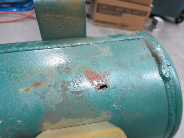
10 - Rusted hole

But I was curious: OK, it’s rusty. But how rusty? During a lull in projects (waiting for some parts to arrive) I pulled out the angle grinder, attached the cutting wheel, and merrily started making sparks.

20 - Grinder

As I made progress cutting, I noticed chunks of degraded metal were falling out of the gap I had cut. Not flakes of rust – chunks of varying color and texture. This is my first hint things are about to get ugly. Once I cut enough to pull away the end of the tank, we can see inside.
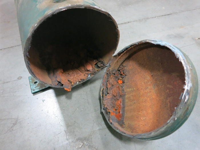
30 - Cut open

That’s far more corrosion than I had expected. And while most of the inside surface qualifies as “rusty” the bottom part deserves a stronger word. I can think of a few, but the only one I am willing to put in print is “Yuck”.

40 - Closeup

This sight is something I might expect to see in a home plumbing project fixing the sewer pipe. And this stuff has the soft squishy consistency of… well, the kind buildup you’d find in a sewer drain. This is not something I expected to see inside a piece of industrial equipment.

50 - Full Length

This layer has built up across the entire bottom part of the air tank.

I had originally thought it’d be neat to find the other side of the perforated hole but I was not in the mood to dig through this muck. Even while wearing gloves.

So let this be a lesson to everybody: If you have a compressed air tank, be sure to drain the water out of it regularly, or this might happen to you!

(Cross-posted to Hackaday.io)

Thermoforming Machine Low Amperage Systems Test

We got far enough wiring (and re-wiring) the thermoforming machine to perform an integration test of the low-amperage parts of the machine. This covers almost everything except the heating element.

LowAmpTestSuccess

On the previous test of the compressed air subsystem, we found a leak in the air tank. The leaky tank has since been replaced and this will be a test to see if it works with everything else.

The vacuum subsystem had also been partially tested earlier. For the previous test we only got as far as the vacuum table solenoid. This time we also have the vacuum lines between the solenoid and the vacuum table.

The relay panel had been tested with the following configuration:

  • 24V bench power supply as the input.
  • Manually connecting the control wires in turn like an old style telephone switchboard.
  • Multi-meter reading the output.

This time, the test will put the relay panel in a more realistic configuration:

  • Power will come from the 240V AC to 24V DC power supply on the DIN rail.
  • The control signals will come from the manual operation toggle switch panel.
  • And the most exciting part: the outputs are going to the actual air and vacuum components!

There was much anticipation and trepidation when the power switch was thrown the first time and we see LED indicators on the power supply indicating the system was live. Every switch thrown was a “Will it work?” mystery. The test did its job, exposing a few wiring errors. Fortunately none of them were damaging mistakes and all were trivial to fix.

At the end of the evening, we could control everything except the heating element using the manual operation switch panel: Move all the air cylinders, open and close all the air valves, and activate the electromagnets that hold the frame closed.

We still have lots of things on the to-do list, including some air leaks to track down and fix and plenty of wiring tasks. And there’s still the big intimidating heating element looming in the near future. But all in all, a wonderful morale boosting step on the journey to completion.

(Cross-posted to Hackaday.io)

The Ever-Growing Wiring Job

When we started on this thermoforming machine rebuild project, one of the first things we did was to open the control panel. We looked at the nest of wires back there and tossed the whole tangled mess. Those control wires were a basket case we’re happy to leave behind. But the rest of the machine – the power cables and such – looked OK at first glance.

Unfortunately, they don’t look as good after the second or third glances. Sometimes it’s not a glance at all – it’s seeing (and feeling) them fall apart when we worked in the machine. We expected the wires to be old, and kept our eyes open for signs of aging wires. We just didn’t expect to see them quite so often! This particular example was from the back of the air compressor. When we wanted to clean up the air compressor, we had to disconnect these wires. The act of moving the wires for access and removal broke the age-hardened insulation in many places. So now we have to replace it.

Failing insulation

Every time we get to work on a new area, we find that a new bunch of wires need to be replaced. We’re rapidly approaching the point where it might be easier to rip out every single wire and restart from scratch.

Wiring is tedious work, part of why good electricians make good money. For us, it’s a very real threat against project completion. We’re interested in having our own thermoforming machine, but that interest tends to drop every time we discover 2 new wiring tasks for every one completed. It’s a race to complete before everyone loses interest in the project.

Hopefully the work will be much easier – or at least more rewarding – once the wiring is complete.

Assuming, or course, we get there…

(Cross-posted to Hackaday.io)

Vacuum Table Frame Removal

Around the periphery of the vacuum table on the thermoforming machine, the previous owners built a perimeter using L-brackets. The presence of the frame made sense to help seal in the vacuum. The mystery is the height: The vacuum table and its surrounding frame are the same height as the combined height of the top and bottom parts of the frame holding the workpiece. We had expected the vacuum table to be aligned with the bottom part of the frame, since that’s the height the workpiece will be held at. As this frame is double the height, it would have impacted the workpiece on the way down. We’re left scratching our heads figuring out why this is desirable.

But that mystery isn’t important right now. Since we intend to put this machine to work on low-volume hobbyist projects, we will want to change the size of the workpiece frequently. This would be difficult with the existing system, since changing the size of the workpiece means changing the surrounding frame, greatly increasing the up-front setup work. It might be fine for a commercial production machine but such a barrier on a hobbyist machine would probably mean we’d be too lazy to actually use it.

We’re bouncing around a few ideas that should make it easier to change the size of the work piece in the machine. All of those ideas are incompatible with this existing taller-than-expected frame, so it needs to be removed.

A few jabs with a metal putty knife got things going and the frame popped off shortly afterwards.

Frame Removal

Then the tedious part starts: the putty knives went to work scraping off the sealant that was liberally applied to the bottom of the frame.

Putty Removal

Part of the motivation to invent a new vacuum sealing system is visible here: this surface is quite scratched up and rusty. To make it seal properly with the old system, we need to remove all the paint, sand things flat, and put on a new smooth coat of paint. If we can avoid that work with a clever new sealing system, we’d be happy.

(Cross-posted to Hackaday.io)

Vacuum Subsystem Test

Since we just tested the air subsystem and found problems that will probably require buying parts from McMaster-Carr, we decided to perform a vacuum subsystem test with what we already have on hand to see if we need to add anything else to the shopping list. Only some of the fittings and vacuum lines have been replaced, and the vacuum table itself is in pieces, but we can put together enough to test the vacuum pump, the accumulator tank, the solenoid-actuated vacuum valve, and the fittings and lines connecting them.

We were happy to see the system could generate vacuum beyond an indicated 25 inches of mercury. This measurement is taken with a grain of salt coming from the old vacuum gauge that was on the machine. But while the absolute value (“25 inches”) might be suspect, the relative value is still useful information. We shut off the vacuum pump and went to work on other things. After 15 minutes, the vacuum held steady enough that there was no visible movement of the needle.

Vacuum Holding

The next test is the rate at which vacuum is generated. We don’t need it to be super fast, but we don’t want it to be the limiting factor in cycle time. As soon as the softened workpiece is pulled against the mold, the vacuum should start building back up. It can continue doing so as the completed workpiece is removed and the next workpiece is loaded and heated. By the time the next piece is heated, we want to have sufficient vacuum in the system ready to go instead of having to wait.

Using the solenoid, we opened the valve and admit air into the system, dropping the vacuum down to an indicated 5″ Hg. We closed the valve and started writing down the vacuum reading relative to a stopwatch.

Vacuum Recovery

The recovery rate is acceptable. After one minute it was back up to an indicated 23″ and 90 seconds brings us to 25″. It didn’t have much grunt beyond that – it took double the time (an additional 90 seconds or 3 minutes total) to reach 26.5″, where the needle stopped moving.

We expect a new pump to recover vacuum more quickly, and provide a stronger vacuum, than this tired old thing. But this performance indicates the vacuum pump will not be the limiting factor in our cycle time and that’s good enough.

(Cross-posted to the Hackaday.io project page.)

New Compressed Air Fittings and Lines

We’ve just completed the milestone of replacing the compressed air fittings and lines in the thermoforming machine being rebuilt at Tux-Lab. We replaced the fittings because we expect the old air seals within them to have decayed with age. Since we have everything disassembled, replacing them now is relatively easy and reduces many potential points of failure.

New Air Fitting

The same logic also applied to replacing lines carrying compressed air throughout the machine. For extra bonus, the new air lines are blue and the old ones are green, making it instantly visible which pieces have been replaced.

New Air Line

Once the compressed air subsystem was buttoned up, we wanted to do a subsystem test. Since we have yet to wire up the 220V power distribution, we can’t run the built-in air compressor just yet. So we unplugged the output port of the air compressor and plugged that into the shop air.

Loud hissing announced the presence of a leak in the system. We felt all around the newly installed air lines and fittings, but the source of the leak wasn’t any of the new stuff. We eventually located the source of the leak to the compressed air tank that we had not yet touched. Before this test, the quality of the air tank was a question mark. Now that we have finally pulled it out and gave it a good look, we have answer to that question!

Holey Tank

During disassembly we noted there was no air dryer between the compressor and the tank, so moisture would have collected in this tank. There is a fluid drain port (not visible in this picture) but it doesn’t look like it has ever been used. This hole implies the inside of the tank is a rusty mess and a hole patch repair would only be a futile short-term solution. If we want a self-contained machine not dependent on shop air we will need to replace this tank.

After this discovery, we disconnected the air line from the output port of this tank and hooked that up to shop air. It allowed us to test the rest of the machine.

  • The mechanism to move the heater rearward seems OK.
  • The mechanism to move the heater forward has a leak that needs to be investigated.
  • Trying to move the heater forward/back repeatedly showed no problems (aside from the above leak.)
  • The mechanism to move the frame up/down each seems OK individually.
  • Trying to actuate up/down movement rapidly would cause the two sides of the air cylinder to fight each other. We are missing an air relief mechanism somewhere in the system. Either we forgot we removed something during disassembly, or an existing relief mechanism has plugged up.

(Cross-posted to the Hackaday.io project page.)

Raspberry Pi Pin Initial States are a Consideration For Machine Control

As an intermediate step towards controlling the thermoforming machine with the Raspberry Pi, we populated a breadboard with some components we planned to use. A Raspberry Pi could only source a total of 50mA of power across all the IO pins, so we had it switch circuits on/off via opto-isolators that required far less current to activate. We started by using these opto-isolators to control power to LEDs. Just to see how it works and make sure nothing unexpected occurs before we start hooking up bigger things.

This proved to be wise, as it exposed some Raspberry Pi behavior we did not expect. When the Pi was powered-up, some of the LEDs glowed dimly. They’re not full bright, but they’re definitely not dark, either. Once the control program starts up and all pins are initialized to off, they go dark as expected. But there’s something going on between initial power-on and when the control program starts running.

This was important to chase down because we don’t want the machine relay to close when we’re not expecting them to close. Even worse if it occurs while the system is powering up and components are not yet in known good states. Making this an important consideration in designing our system.

A bit of web searching confirmed this startup behavior was noticed and investigated by a lot of people looking at various parts of the system. The answer was most succinctly answered by a post on the Raspberry Pi subsection of StackExchange: In the peripherals manual for the BCM2835 chip at the core of the Raspberry Pi, the power-on initial states are explicitly stated: All IO pins are configured to be input and not output. Furthermore, pins 0-8 are set with pull-up to 3.3V and pins 9-27 are pulled-down to 0V.

Looking back on the breadboard, we could confirm the explanation matches the observed behavior. The dimly lit LEDs were controlled by opto-isolators that were, in turn, connected to Raspberry Pi pins 5 and 6. None of the other isolators were controlled by pins in the 0-8 range. Since opto-isolators required so little current to operate, the weak pull-up on a pin set to input was sufficient to partially activate the circuit.

Once the cause was determined the solution was simple: move all output control out of the 0-8 range of pins. These pins would be fine for input, so the task of reading the position of a limit switch was moved to pin 5.

The resulting breadboard is visible in the attached image, and the code was changed to match the new pin assignments in this commit. After these changes, we observed no partially lit LEDs which also hopefully means no unexpected relay activity when we hook it up to the machine.

IMG_5266

Setting Up Raspberry Pi GPIO Pins For Device Control

A rough draft of the thermoformer touchscreen control panel application, witting in Python with the Qt UI framework, is now up and running. Now it is time to see how it works controlling some physical hardware. We’re going to build up to this in steps on the way towards actually controlling the thermoform machine. The first step is to have the Pi light up some LEDs as commanded by the control panel application.

I had been playing with a Microchip PIC16F18456 earlier, which can drive LEDs effortlessly. Each pin can handle 50mA which is more than enough to drive LEDs as they typically require no more than 20mA each. I had assumed the Pi would be even more capable with its onboard voltage regulators, but I thought it’d be better to check just to be safe. I’m glad I did! It turns out the pins on the Raspberry Pi has significantly lower power capability than the pins on the PIC16F18345.

The consensus on the Raspberry Pi forums says the limit is 16mA per pin, and 50mA total across all pins. A bunch of LEDs would quickly exceed the 50mA total cap. Given this, we’re going to take two baby steps at once.

We’ve known we couldn’t drive the thermoforming machine directly with Pi. And even if we could, a direct connection is not the best idea. The plan had always called for the use of opto-isolators to keep some separation between the delicate low-power circuitry on the Raspberry Pi chip and the high-power components of the machine. I just didn’t expect that bright LEDs to qualify as “high power” in this context. But since they are, we’re going to use opto-isolators to build the LED proof of concept.

The current design for the control has 9 outputs to relays, and 1 input from a limit switch. For the outputs we’re starting with the Vishay 4N32 chip to see how they work. For input, we wanted a chip that works in the reverse direction, and we’re starting with the Toshiba TLP2200. With the help of a Raspberry Pi I/O breakout board we could hook everything up on a breadboard for the first test.

IMG_5266

Learning Timers: Qt QTimer and Python threading.Timer

QtLogoWhen I interfaced my PyQt application to the Raspberry Pi GPIO pins, I ran into a classic problem: the need to perform input debouncing. The classic solution is to have the software wait a bit before deciding whether the input change is noise to be ignored or not. A simple concept, but “wait a bit” can get complicated in the world of GUI programming. When writing simple programs, we can probably get away with a literal wait by “going to sleep” for a little bit. But we don’t have that luxury in the world of GUI programming – going to sleep would freeze everything in the program. In general, users do not appreciate their UI becoming frozen and unresponsive.

Python LogoThe solution: a timer. In a Windows application, the programmer can use the operating system timer and do their “after waiting a bit” tasks in response to the WM_TIMER message. I went looking for the Qt equivalent and found several timer-related features. QTimer, QBasicTimer, and QObject::startTimer(). Thankfully, the documentation also provided an overview describing how they differ. For debounce purposes, the most fitting mechanism is a single-shot timer.

Unfortunately, when I tried to use it, I received an error message telling me I could only use Qt timer objects from code launched with QThread. Which apparently wasn’t the case with code running under the context of a QWidget within a QApplication.

I had hoped the Qt timers, working off of the QApplication event queue, would stay on the UI thread. But it appears they have to have their own QThread. I could put in more time to figure out how to get Qt timers to work, but I decided to turn to Python library instead. If I have to deal with multi-threading issues anyway, there’s no reason to avoid Python’s Timer object in the threading library.

It does mean I had to review my code to make sure it would be correct even if called from multiple threads. Since the important state are the status of the GPIO pins, they are handled by the pigpio library and the code in my app should be fairly safe. I do set a flag to avoid creating multiple Timer objects in the case of input bounce. If I cared about making sure I only ever create a single Timer, this flag should be protected against cross-thread access. But reviewing the code I decided it was OK if a few Timer ends up being created – the final result of reading the GPIO pin should still be the same even in the case of multiple Timers doing duplicate work.

(The project discussed in this blog post is publicly available on Github.)

Notes on “ZetCode’s PyQt5 Tutorial” From a Windows Developer.

QtLogoOnce I decided to learn how to create a GUI application using the PyQt5 Python binding for the Qt framework, I looked online for some resources to get started. The reference guides for PyQt5 and Qt version 5 itself seems to be fairly robust, but I needed a little push to get over the initial learning curve to understand where to look for what I need.

The Python Foundation’s wiki for PyQt tutorials has a fairly long list. But when I looked, only one explicitly states it is for PyQt5. So off I go to Zetcode’s PyQt5 Tutorial. It was a very bare-bones tutorial that might be a bit too bare for a complete beginner trying to learn GUI programming. But for somebody who already knows the general concepts of a windowing graphics interface system, it is a quick primer to learn the vocabulary.Python Logo

Since I’ve worked with various flavors of Windows frameworks (from raw Win32, to MFC, to WPF) I just needed a tutorial to help me connect concepts in my head to the terminology used in Qt. For example: in Qt, when something happens, a notification called a “signal” occurs. A signal can be connected to a “slot” which can then respond to whatever just happened. Once I learned this, I was able to translate the concepts into my head: a “signal” is an event that could be raised, and a “slot” is an event handler. Once I got this and a few other basic “Rosetta Stone” translations in my head I could switch to the reference documentation to find answers.

One important note: Even though it is labelled as a PyQt5 tutorial, Zetcode’s tutorial is actually pretty much the PyQt4 tutorial updated with the changes to syntax needed for PyQt5. It doesn’t actually cover anything that is new in Qt5. For me this is fine, because the “old way” covered in the tutorial is probably what I’ll end up using when I go even further back in time for the ROS flavor of Qt.

But know there’s no coverage of the Qt5 advancements in declarative interface construction, hardware-accelerated rendering, etc. Anybody who wants to learn the new toys of Qt 5 would have to look elsewhere.

Qt + Python = GUI for Raspberry Pi Project

Since the mission of the Raspberry Pi foundation is to “put the power of digital making into the hands of people all over the world” there is no shortage of options for programming the Pi. We have at our disposal many choices in programming languages, each with multiple application frameworks, and a large community of Raspberry Pi users for support.

QtLogoFeeling overwhelmed with options, I chose the one that best lines up with my long-term goal of getting up and running on ROS. The ROS plug-in architecture for operator GUI is rqt, based on Qt. And like much of ROS, the user has the option of working with rqt in either C++ or Python. Since I had started dabbling with ROS in Python before getting distracted, I thought the combination of Qt and Python would be a good direction to go.Python Logo

The Qt framework itself is aimed at C++ developers, and its documentation is written accordingly. Fortunately there are translation layers (language bindings) for Python. The one that seems to be the most mature is PyQt with a long list of resources, books, and online tutorials.

The next decision to make is which version to start learning. Browsing through the resources, it looks like Qt 4 is the mainstream version and Qt 5 is the new shiny. Since ROS is still in the midst of transitioning from Python 2 to Python 3, I assume rqt would be relatively old school as well. No matter which one I choose, there’ll be differences I have to tackle whenever I get around to diving deep into ROS. On the assumption that the latest and greatest versions are also the most polished (an assumption based on how Python 3 cleaned up a lot of architectural messiness of Python 2) I thought I’d start learning with the latest releases and make adjustments later as I need to.

So: Qt 5 and Python 3 it is, with the help of PyQt5 binding. Which is easily installed on a Raspbian Stretch system by installing the packages “pyqt5-dev” and “pyqt5-dev-tools”.

New Project: Thermoforming Machine Touchscreen Control

I help where I can in the Tux-Lab effort to rebuild the old thermoforming machine. I’ve been doing more learning than helping, though, since others have more experience with industrial machinery than I do. The initial goal is to get things up and running under manual control, and we’ll tackle automation later.

That doesn’t keep us from chatting about ideas for the automation effort, which is roughly divided up into three tiers of complexity.

At the low-end, we can drive it with a PIC micro controller. A modern PIC should be more than capable of duplicating the level of automation that existed in a decades-old machine. It would be the lowest-cost solution, if the cost difference was significant enough to matter.

The mid-tier option is an Arduino. It should be the easiest to get up and running due to the components already integrated on an Arduino board and the large existing library of code we can draw upon.

Both of the above would offer the option of reusing the control panel as-is, which would be important if we wanted to preserve the exterior appearance of the machine. At the moment it is not a goal to do so – we are not a museum and see little value in historical preservation on this machine. Especially since it’s a huge mess of wires in there.

IMG_5242

So, as can be expected of a bunch of tinkerer types, the dreams started getting wilder and wilder. It wasn’t long before we started talking about a touchscreen-controlled thermoforming machine that is network-connected for job monitoring and logging. Which leads us to the high-tier option: a Raspberry Pi with the matching LCD touchscreen.

The team has members with experience in PIC programming, and in Arduino programming, but we’re light on Raspberry Pi programming expertise. Since this is something I wanted to learn to do anyway, I volunteered to investigate.

In the short term we’re still focused on the manual toggle switch operation mode. In the medium term we might still implement Arduino control. And that might be a good enough place to stop, but I wanted to see if we can turn the wild dream into reality.

Tux-Lab Thermoforming Machine Disassembly

One of the projects on the Tux-Lab to-do list is to revive a thermoforming machine. Purchased cheaply in non-working condition, it has potential to enable some very interesting projects. It has been gathering dust while waiting for enough interest from enough people to reach critical mass to start the project. I think we finally reached that point! We pulled it out of the corner it’s been sitting in, and merrily started pulling everything apart.

Disassembled

I thought we would document the original condition as we pulled things apart, but it quickly became apparent there’s no “original condition” to document. The wide range of age and quality of components made it clear it has seen continual modifications in its decades of service. The decision was made to go all the way back to fundamentals.

The bottom cabinet held the air machinery: a vacuum pump and an air compressor, each with an associated accumulator tank. They had all been bypassed with external connectors, which was not a vote of confidence in their functionality. We were hopeful that the previous owner(s) just wanted to reduce noise and vibration by hooking into their shop’s existing compressed air and vacuum lines.

The vacuum pump turned and could pull 26 inches of mercury, which is quite acceptable. The air compressor pushed out 40 psi, which was rather was less so. Fortunately a disassembly and cleanup was enough to help it push 100 psi. The two air tanks are question marks.

There are two air cylinders in this machine: One moves the thermoforming frame up and down, the other  moves the heater front and back. A quick test of both revealed they move and no air leak hissing was audible at either of their end positions.

The thermoforming frame was designed with two electromagnets to hold it closed. We assumed the magnets were broken because somebody installed some Home Depot quality mechanical latches. But we were able to energize the coils and feel it hold. Maybe the failure was in the control circuitry, maybe it doesn’t hold strongly enough for some task. We’ll find out for sure later.

Latch

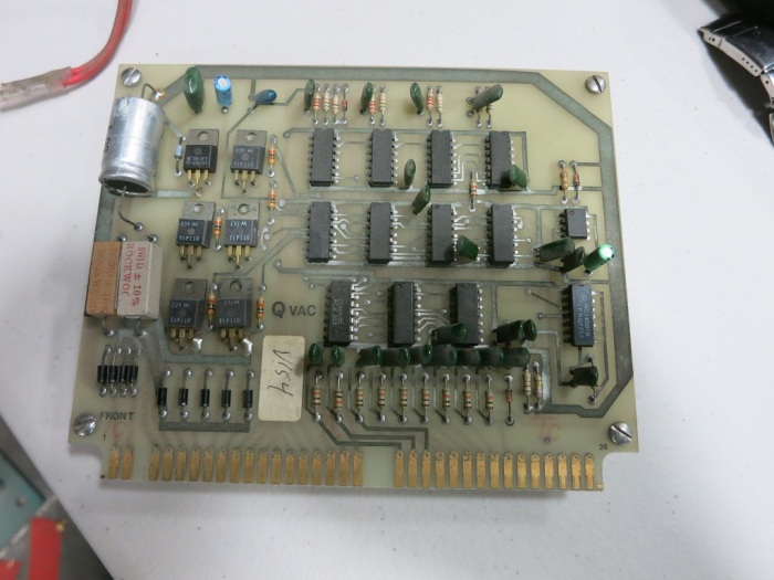
The brains of the machine are the clearest indication of the age. We see a lot of discrete logic components and no indication of a microcontroller at the heart of it all. The control panel has a button “Automatic” and we wonder what that used to do. For the moment we will not worry about it: the initial milestone is to get it up and running in manual operation mode. If we get around to implementing an automatic cycle, we’ll pull in an Arduino or something modern to orchestrate the various bits and pieces.

Brains

On the assumption that old air hoses and fittings will be leaky, they will be replaced with new parts. The air valves should still be good and will be used until proven otherwise. Same for the big honkin’ contactors (240V, 40A) in the back to control the heater.

Orders have been placed for replacement parts – once they show up we can install them to get a better idea of how everything will (or won’t) work together.

(This project is cross-posted to Hackaday.io)