VGA Signal Generation with PIC Feasible

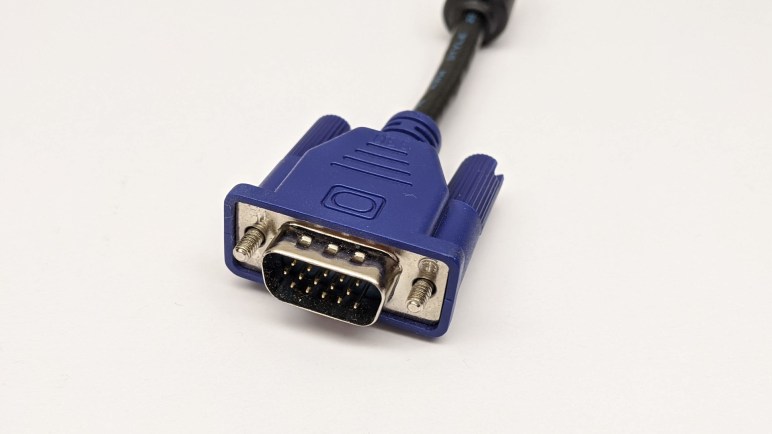
Trying to turn a flawed computer monitor into an adjustable color lighting panel, I started investigating ways to generate a VGA signal. I’ve experimented with Arduino and tried to build a Teensy solution, without success so far. If I wanted full white maybe augmented by a fixed set of patterns, Emily suggested the solution of getting a VGA monitor tester.

They are available really cheaply on Amazon. (*) And even cheaper on eBay. If I just wanted full white this would be easy, fast, and cheap. But I am enchanted with the idea of adjustable color, and I also want to learn, so this whole concept is going to stay on the project to-do list somewhere. Probably not the top, but I wanted to do a bit more research before I set it aside.

One thing Emily and I noticed was that when we zoomed in on some of these VGA monitor testers, we can tell they are built around a PIC microcontroller. My first thought was “How can they do that? a PIC doesn’t have enough memory for a frame buffer.” But then i remembered that these test patterns don’t need a full frame buffer, and furthermore, neither do I for my needs. This is why I thought I could chop out the DMA code in the Teensy uVGA library to make it run on a LC, keeping only the HSYNC & VSYNC signal generation.

But if I can get the same kind of thing on a PIC, that might be even simpler. Looking up VGA timing signal requirements, I found that the official source is a specification called Generalized Timing Formula (GTF) which is available from the Video Electronics Standards Association (VESA) for $350 USD.

I didn’t want to spend that kind of money, so I turned to less official sources. I found a web site dedicated to VGA microcontroller projects and it has tables listing timing for popular VGA resolutions. I thought I should focus first on the lowest common denominator, 640×480 @ 60Hz.

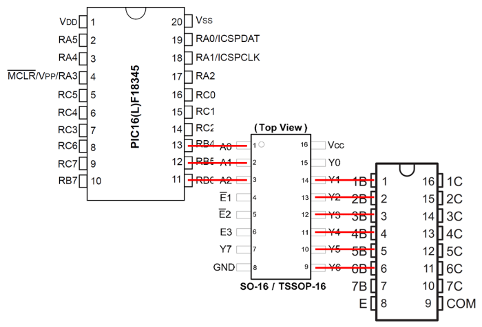
The PIC16F18345 I’ve been playing with has an internal oscillator that can be configured to run at up to 32 MHz. This translates to 0.03125 microseconds per clock, which should be capable of meeting timing requirements for 640×480.

I thought about leaving the PIC out of the color signal generation entirely, have a separate circuit generate the RGB values constantly. But I learned this would confuse some computer monitors who try not to lose data. So we need to pull RGB values down to zero (black) when not actively transmitting screen data. It would be more complex than just focusing on HSYNC/VSYNC but not a deal breaker.

[UPDATE: I continued this project with an ESP32.]


(*) Disclosure: As an Amazon Associate I earn from qualifying purchases.

Casualty In Debugging 5V Supply for Prototype VFD Driver

Once we had functionality of our prototype VFD driver figured out, we turned our attention to the other problem that cropped up earlier in our initial integration with the original power supply transformer: our 5V rail could support the PIC microcontroller and associated chips, plus putting a voltage bias on the filament. But when put a Raspberry Pi on the circuit, our 5V sagged low enough to put our Pi into a power brown-out reset loop.

Since the MP1584 voltage regulator we used has proven capable of powering a Pi in the past, this was puzzling. So we started quantifying our system starting with measuring the amperage draw of our 5V circuit. It was well within the 3A maximum draw supported by the regulator, so our next thought was a dirty output wave. Putting the output on an oscilloscope, the 5V line looked pretty clean so that was not the explanation.

The next experiment was to isolate the 5V supply chain. Instead of supplying the MP1584 voltage regulator with power from the rectified output of a transformer rail, we’re going to use a two-cell lithium polymer battery. If this worked, we’ll know the problem is upstream in the transformer or rectifier. If it doesn’t, we’ll know the problem is the regulator or further downstream.

Unfortunately the experiment failed due to a wiring error, which destroyed the MP1584 voltage regulator. The title picture shows the entire regulator module with a U.S. quarter dollar coin for scale.

And here’s a close-up of the dead MP1584 chip. The glossy blob in the upper left is plastic that has melted and resolidified. The bump in the middle was a tiny volcano where smoke pushed up through the casing and escaped.

MP1584EN chip with melted hole

Looking on the bright side, we are no longer suspicious of the MP1584 chip’s functionality. We now know for sure it doesn’t work!

Debugging continued with help of a benchtop power supply delivering 5V. Probing with a volt meter through the circuit, and seeing voltage drop along the supply path, we decided our problem wasn’t any single wiring errors in the circuit. We just had too many thin wires and connectors involved in the 5V supply path. We had put our Raspberry Pi at the end of the chain of 5V parts, and it couldn’t draw enough power to run. Not because of any single large obstacle but because of the cumulative effect of lots of little obstacles.

To test this hypothesis, we reversed the chain so our 5V supply entered the system at the Pi then propagated to the rest of the circuit. With this change — and no other change in the circuit — everything started working. This is a valuable lesson to a software person who is used to thinking in terms of digital logic: It’s easy to think 5V rail is 5V as long as there are wires connecting them. This simplification creates a blind spot: the real world is analog and our 5V rail will degrade to a 4V rail when too-thin wires are used!

With that problem solved, we can now start playing with VFD patterns. See what works and see what doesn’t.


Prototype VFD Driver PCB Debugged

We now pick up where we left off narrowing down a problem with our prototype vacuum fluorescent display (VFD) driver board. We had determined that segment H was the key. When segment H was illuminated, everything else works as expected. But when segment H was dark, segments A-G all became dark as well.

ULN2003
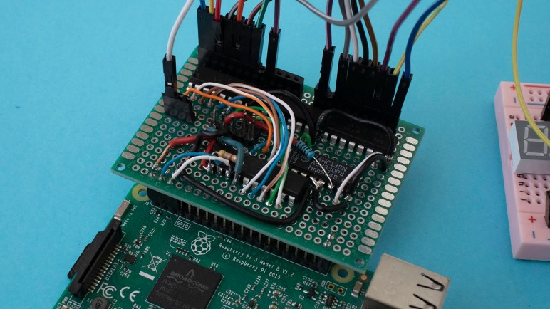
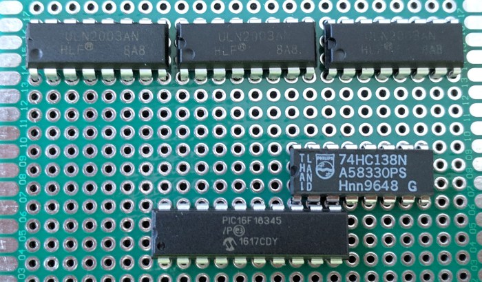
Since segments A-G were all controlled by a single ULN2003 chip, we started looking closely at every solder joint on that chip. We were looking for an undesirable solder bridge or other electrical connection to any wire relating to segment H, which was managed by another ULN2003 chip.

The two ULN2003 chips were immediately adjacent to each other, meaning A-G were pins 1-7 on one chip, and segment H was pin 1 on the next chip. The densely packed nature of these chips meant pin 1 of segment H was immediately adjacent to the emitter (E) and common (COM) pins of the ULN2003 controlling A-G.

When describing the symptoms, [David] correctly diagnosed the problem must be an electrical connection between segment H pin 1 of one ULN2003, and pin COM of the adjacent ULN2003. Using a probe we verified this was indeed the case – those two pins should have no connection but they are electrically connected. However, we could not find where this connection was taking place. No solder bridges were found and no accidentally soldered wires were found.

Eventually [Emily] devised a hack: because a VFD is not an inductive load, we didn’t really need the COM pin at all. It was only soldered to the board for physical mounting, that solder joint has proven to be more trouble than it was worth. To bypass the undesired connection, wherever it might be, it is easiest to clip off the COM pin from that ULN2003. Maneuvering a cutter within the packed space, [Emily] snipped off the leg.

After that, every aspect of our prototype VFD driver was fully functional as planned. [Emily]’s hack was totally unconventional, but very effective!

Salvaged VFD Power Supply And Debugging

Our first system integration test of a salvaged vacuum fluorescent display (VFD) and our prototype driver PCB was a success. At least going by our initial target of having our VFD segments illuminated and cycling through a test pattern to verify things are not stuck always on or off.

Once we had that basic level of functionality, [Emily] started working on the power supply side of the system. We have an original transformer salvaged from the same device which outputs multiple AC voltages. The first is a 2.5V AC line we could use directly on VFD filament. After that, Emily salvaged a few more components to deliver the ~30V DC we need for control grid and segments, and the ~24V DC we fed into a MP1584 buck converter to get 5V DC for filament bias and micro controller logic power.

VFD on transformer

We’re very close to a complete power solution for a VFD project, but not quite there yet. When we added a Raspberry Pi 3 to the mix, its power demand was too high for this system to handle. Power sagged to 4.2V and the Pi entered a power brown-out reset loop. We’re not sure what’s wrong with this setup yet, but in the meantime we connected an alternate 5V DC power source to look at how the rest of the system behaves.

This allowed us to see a problem in our prototype driver board. I had a new test pattern generated with the help of my tool created in Google Sheets, but the test program did not display as I expected. After some time sending various diagnostic patterns to the VFD, we figured out the key to the situation is segment H.

NEC VSL0010-A VFD Annotated

Whenever segment H is illuminated, everything else functioned as expected. But if segment H is dark, segments A-G are all dark regardless of commanded pattern. Segment I and J are unaffected.

Once this was determined, we ran a test pattern where H is commanded to be dark and everything else should illuminate. The test pattern is the same for every segment, so the circuit would be at a steady state for us to probe with a meter as the PIC cycled through segments.

Using segment A as an example, we probed to verify its output pin from PIC (RC0) is low as expected. We then traced that signal to the ULN2003, whose corresponding input pin is low as expected. With input low, the corresponding ULN2003 output pin should not be tied to ground. Which means we expect VFD pin for segment A to be sitting at near 30V DC due to a pull-up resistor.

This is where we went off script, for VFD pin A has been pulled low. Unplugging the wire between ULN2003 and VFD allowed the segment to illuminate. This narrows down the scope of our problem: it has something to do with that ULN2003 chip, but we ran out of time for tonight’s SGVHAK session before we could narrow it down any further.

To be continued!

Create VFD Bit Pattern With Help Of Google Sheets

With a successful integration test of our salvaged vacuum fluorescent display (VFD) we proceed to a few other tasks. On the hardware side, we’ll need to simplify our power supply situation. Our test had three separate AC plugs, we only really need one. We’ll also need to transfer what’s on the breadboard to a prototype circuit board.

On the software side, things are less clear because we’re still coming up with ideas on what to do with a salvaged VFD. Our very simple PIC driver code merely controls a pattern of bits, each bit representing a segment to be illuminated. This gives us a lot of flexibility but so far these bit patterns have been created using pencil and paper and quite time consuming. Once we have a project in mind we can write code specific to a theme, but until then it’s wide-open bits.

Well, at least we can streamline the pencil and paper system somewhat. The logic is not difficult, just time consume, and should be easy to automate. I started by creating a HTML form and laying out checkbox controls. I got as far as designing a JavaScript structure for checkbox click events when I realized everything is on a grid and looks a lot like a spreadsheet.

That realization led me to put my basic HTML and JavaScript on hold and switch to investigate what I can do in Google Sheets. The key that made it all possible is the BINTOHEX() function that reads a number, interpret it as binary, and translate to hexadecimal. This is the core functionality for my pattern generation and I was able to build everything else around it.

Here’s the initial build, with a fully populated grid of checkboxes and a test pattern for me to verify things were working.

VFD Pattern tool - full checkboxes

Once verified, I deleted the checkboxes that didn’t have a corresponding segment. This array now properly corresponds to our specific VFD.

VFD Pattern tool - customized checkboxes

Now creating a bit pattern is as simple as checking on the segments I wish to have illuminated. Here’s the pattern for “12:00”, the canonical Hello World for a time-based VFD display.

VFD Pattern tool - 12.00

I thought it would be fun to make this available for anyone to play with, but that requires keeping the sheet and its formulas fixed while allowing people to check and uncheck boxes. Unfortunately “view only” sharing does not allow checkbox manipulation, and “editable” sharing also allows modifying the sheet formula. Until I figure out how to do what I want, it was shared as “View Only” to the general public.


Integration of Salvaged VFD and Prototype Driver PCB

The time has finally come to put our salvaged vacuum fluorescent display (VFD) together with the prototype driver printed circuit board (PCB) we built for it. First we gave our VFD a little layer of protection. The individual pins of the VFD are small and seemed rather fragile. And as they went into a vacuum sealed chamber we had no means to repair, if one pin should break that would mark the end of our fun.

Fortunately, when we salvaged it from its previous home we noticed that those pins were quite strong in union. A single pin is fragile, but all twenty pins together was pretty strong. So we’ll solder up one of our cheap prototype boards to these pins just for the sake of holding them together. It was a bit tedious getting all the pins to line up. Two more boards were used as spacers to give us the desired distance.

VFD pin alignment

Once lined up, the VFD was soldered in place.

VFD pins in perf board

As anticipated, the assembly is now much more robust. Now we can work with this module with a lot less trepidation: if we should break a pin now, the break should stop at this PCB where we could still recover, not break all the way to VFD glass where we couldn’t.

We still had a lot of usable pin length remaining, so we left this unionizing PCB alone and soldered another one where we’ll actually attach wires and headers.

VFD second PCB

While this soldering work was underway, a breadboard was populated to test our design for interfacing our driver PCB and the VFD. Each VFD grid and segment wire received a 10 kilo-ohm pull-up resistor to the 30V line, and path cords were installed to map pins from our generic driver board to this specific VFD as per the pinout diagram we drew up earlier. Now the VFD, with its new more robust pins, should plug right in.

VFD interface breadboard

Finally, power delivery which is far more complex than what a LED project requires. This initial integration test had three different power sources. The power transformer we salvaged alongside this VFD delivers (among other voltages) the ~2.5V AC we need for our filament. With a few rectifier circuits, it should be able to deliver the other DC voltages we need as well, but we weren’t going to worry about it until we got this test working. In the meantime, a HP inkjet printer power supply delivered the 30V DC for grids and segments, and a Raspberry Pi delivers the 5V logic power as well as I²C control signals.

VFD integration test rig

We plugged everything in and… it lives again under our control!

Prototype VFD Driver Tested With Placeholder LED

PIC16F18345 VFD driver PCB

Once I had assembled our first prototype vacuum fluorescent display (VFD) driver circuit board, it’s tempting to connect it right up to our salvaged VFD and bask in its glow. But that would have been premature: there were bugs still to be ironed out with potential for fatal errors to damage or destroy our one and only salvaged VFD.

The first tests were what we used to test our bread board prototype: drive a 4-digit 7-segment LED, a Lite-On LTC4627-JR from my earlier PIC display driver project. From there I could verify 8 of 11 segments on this driver board functioned as expected by a demo program that constantly flips between two patterns, one spells “Hello” and the other “Ahoy”.

I then tested the I²C capability with a small update, changing the second pattern from “Anoy” to a very mutilated “MLE”. (It’s hard to do “M” on 7 segments.)

These experiments exposed a few minor bugs, just as tests were supposed to. After they were fixed I expanded my test with a second LTC4627-JR for eight total segments. I also expanded my use of I²C by continuously updating all digits from Raspberry Pi to create a text marquee. This experiment exposed some timing issues that is visible as a slight lag just as the “u” in “thank you” came up on screen.

That lag was diagnosed to my code inside a timer interrupt service routine (ISR). On a simple chip like this PIC, a hardware interrupt signal could not interrupt another ISR already in progress. So when my code inside a timer ISR grew beyond a certain point, it started interfering with timely response to hardware interrupts necessary for I²C communication. The solution is to put my timer ISR on a severe diet, moving almost all of its bulk elsewhere so that I²C handlers could run with minimal interference.

Once the software problems were sorted out, I started experimenting with the flexibility given by this project’s design decision to keep PIC code simple. It meant I could play with patterns that have nothing to do with displaying letters or text. I decided to try a pattern that keeps a single lighted segment running through the display in a figure 8. When cycled through all digits like a text marquee, it gave us a neat looking wave. I look forward to more experiments in driving a multi-segmented display in unusual ways.

Assembling Prototype VFD Driver PCB

PIC16F18345 VFD driver PCBIn addition to exploring the idea of aggressively packing chips densely, there were a few other design considerations in building our prototype driver PCB.

Why I²C?

When I was tearing my hair out trying to figure out why a tried-and-true piece of template code has stopped working, I was sorely tempted to move to some communication protocol other than I²C… good old TTL Serial always looks good whenever I run into a problem.

The answer is voltage compatibility: I want my driver board to be capable of running at either 3.3V or 5V, which is easy to do with an old 8-bit chip like the PIC16F18345 I’m using: give it power anywhere in its specified range (and probably a bit beyond that range) and it’ll happy run. But this doesn’t necessarily apply to whatever my driver board will accept commands from. Fortunately, I²C was designed from the start to accommodate devices that work off different VCC levels. So something like a Raspberry Pi (3.3V) can communicate with my PIC. (5V).

Pin Assignments

In addition to moving the decoder output pins so it could be placed immediately adjacent to my PIC, I also took advantage of my particular PIC’s feature of Peripheral Pin Select (PPS) by moving the I²C pins (handled by Master Synchronous Serial Peripheral – MSSP) from their default to RA4 & RA5 for easier routing on the PCB and easier data writes in my code.

Pin Isolation

This is the first time I planned to use pins RA0 and RA1 on a PIC16F18345 project. I usually avoid them because they are used as in-circuit system programming data (ICSPDAT) and clock (ICSPCLK) pins. They’re perfectly usable outside of this scenario, but they must be disconnected from the rest of the circuit during programming. In this case, it meant I had to put in two jumpers that are removed during programming. The jumpers are installed exactly where my PICkit 3 programmer would attach, so there’s no way for me to forget to remove them when reprogramming this chip.

Wires From CAT-5E Network Cable

Even with all these concessions to easier routing on a prototype PCB, there will still be an unavoidable nest of wires. In order to keep things tamed, I harvest my spool of CAT-5E network cable for wires that are thin and rigid. Thin wires help me fit more wires in a small volume, and rigid wires stay where I’ve put them. In addition to being affordable and easily available, the four twisted pairs of wires give me eight different insulation colors to help me keep track of which wire goes where.

Chip Packing Experiment On Prototype VFD Driver PCB

While we were building a breadboard prototype for our VFD driver, we weren’t terribly concerned with chip layout as it was largely constrained by the practicalities of a bread board anyway. Once we start thinking about transferring it to a PCB, however, we had more flexibility to be creative. The prototype printed circuit board is a grid of through-holes that we can use in any way we like. How shall we abuse this power?

While looking at how wires were run on our bread board, I noticed that there were a few pins that were perfectly aligned from one chip to the next. Placing the decoder output on PIC pins RB4, RB5, and RB6 lines them up perfectly with the input pins of 74138 decoder. As for the decoder output, six out of eight pins were directly lined up with a ULN2003.

Chip pin alignment

This allows some fairly straightforward wiring solder as these wires will not cross over each other and won’t tangle up and make a big mess. By itself that is valuable, but we were tempted to go one step further: how about we eliminate the wires entirely and jam those chips together? If they share the same PCB through-hole, that would eliminate wire soldering entirely.

It sounded good in theory, but in practice the chips are just a little too large for us to fit them three-abreast. I could push my decoder up against my PIC, but couldn’t push the Darlington array alongside the decoder as well. This is probably for the best – there’s value in having the ULN2003 lined up with its siblings.

Chips tightly packed on PCB

We may learn in the near future why this is a bad idea, but it’s all part of the fun: trying things and seeing how they work. (Or not, as the case may be.)

Breadboard Prototype of VFD Driver Project

Once we had some idea of what we wanted to do, it’s time to start wiring things up on a breadboard to see if it actually does anything interesting. Dealing with actual chips meant reading their data sheets and figure out where the rubber meets the road and how well theory meets practice.

Not having a lot of first-hand experience with such modules, it was a great way to learn by doing. The first surprise was behavior of the 74HC138 decoder module: Conceptually it takes a three-bit input and decodes it to one of eight pins. Conceptually we thought that meant raising one of eight pins high, but it actually lowers one of eight pins low.

We thought this was going to be a problem and started looking into inverters… before we realized it is a perfect pairing with ULN2003 to do what we actually wanted: The ULN2003 line inverts its input in the sense that when an input pin is high it connects the output pin to ground. So the output of a 74HC138 decoder (seven pins high, one pin low) driving ULN2003 results in seven pins connected to ground and one floating. We can work with this.

A 4-digit, 7-segment LED module stood in for the vacuum fluorescent display while all the logic got worked out. This flexibility is exactly where a breadboard is strong, letting us experiment and verify pieces of our circuit piecemeal. But it is not great for looking respectable or for long-term reliability, so once it successfully ran the LED module, we start planning to commit the design to soldering parts on a prototype PCB.

PIC16F18345 VFD breadboard and PCB

Hardware Side of Keeping PIC Driver Simple

For the VFD driver project, there were software design motivations to keep things simple. But that’s not the whole picture, there were also motivation from hardware constraints too. My previous projects to make a PIC drive a multi-segmented LED display had fairly simple wiring that connected most output pins of my PIC to current-limiting resistors. A few of the lines could have seen current flow higher than what a PIC is capable of handling, and those were handled with simple transistors. I knew there existed chips designed specifically to drive LEDs, but I wanted to learn the principles of controlling one myself.

Building something to drive a VFD requires dealing with voltages different and sometimes far higher than what is required to drive LED display modules. During our probe of this specific VFD we saw 2.5V AC and 30V DC, atypical of logic circuits. And just as there existed dedicated LED driver chips, there exist chips specifically designed to drive VFD modules, but again the project goal was to learn by building one ourselves.

So we turn to our standard electronic hobbyist toolbox item for controlling power and voltage beyond what our standard parts can handle: the ULN2003A line of Darlington arrays. The go-to solution for controlling inductive loads like relays and small motors, it can handle voltages up to 50V which we need for a VFD.

And again, with multiple different display projects on the horizon, it didn’t make sense to create a controller with hardware pinout specifically tailored to a specific unit. To keep things simple and consistent across displays, all of our controller outputs will be either left floating or tied to ground. If a particular device desires a particular pin to be at a higher voltage, we’ll have to wire up a pull-up resistor on that device’s specific interface board. We will learn if this concession to consistency will cause problems down the line.

VFD driver schematic

Why And How Of Simpler PIC Display Driver

Earlier in my outline for starting a new PIC display driver project for a vacuum fluorescent display (VFD), I mentioned one objective was to “keep the PIC side very simple and move more display-specific logic into driving code“. Let’s go into more detail on that part of the plan.

In my previous PIC display projects, the code was written for a specific multi-segment display unit as part of the overall project. This meant the source code reflected whether the LED was a common-anode or common-cathode design, it also knew about which segment represented which parts of a particular digit. This knowledge was required because I put priority on making control communication interface easy. For the temperature demo, making my display unit show “72.3F” was a matter of sending the actual UTF-8 text string “72.3F” as bytes. The PIC then parsed that string and determined which segment to illuminate.

But there’s a good chance we have several other matrix display projects in the future, and I didn’t want to invest the time to hard code intricacies of each unit into the PIC. It would be much easier to adapt and experiment if such logic was moved to a more developer-friendly environment like Python on a Raspberry Pi. In the case of the current NEC VFD under consideration, there are segments corresponding to days of the week and other function specific segments like an “On and “Off” text, “OTR”, little clock icon, etc. Most of which won’t necessarily be present on another VFD unit, why spend the time to embed such knowledge in my PIC driver?

NEC VSL0010-A VFD Annotated

We also want the flexibility to explore using the display in ways that are far afield of its original intent. For starters, that seven-segment display in the center doesn’t have to be constrained to display numbers for a clock. All these desires meant moving away from performing data interpretation on the PIC.

Instead, the PIC will accept a raw data stream where each bit corresponds to whether a segment is on or off. Each byte will correspond to 8 segments in a grid, and so forth. This means the task of mapping a desired digit to a set of segments will be the responsibility of driver code on host device rather than PIC peripheral. PIC will only concern itself with rapidly cycling through the matrix of digits keeping them all illuminated.

Old Microchip MCC Boilerplate for MSSP Requires C90 Compatibility Mode

PIC16F18345 VFD driver PCB

I’ve figured out how to compile the new Microchip Foundation Services Library boilerplate code for implement I²C peripheral, only to learn it doesn’t do what I wanted it to do. Well darn, it’s time to go back to the tried-and-true I²C boilerplate code I’ve used in earlier projects. It’s still there, it compiles with only the “this is outdated” warning, and I knew it worked well enough to be a good starting point for my projects. It was the tried-and-true known quantity that shouldn’t give me any trouble at all.

Except it did.

The code compiled fine, but it didn’t actually work. It would give a response to the first I²C query but then it would stop responding. Here’s the default boilerplate code, which responds to address 0x08, as probed by a Raspberry Pi using i2cdetect tool.

pi@raspberry:~ $ i2cdetect -y 1
     0  1  2  3  4  5  6  7  8  9  a  b  c  d  e  f
00:          -- -- -- -- -- 08 -- -- -- -- -- -- --
10: -- -- -- -- -- -- -- -- -- -- -- -- -- -- -- --
20: -- -- -- -- -- -- -- -- -- -- -- -- -- -- -- --
30: -- -- -- -- -- -- -- -- -- -- -- -- -- -- -- --
40: -- -- -- -- -- -- -- -- -- -- -- -- -- -- -- --
50: -- -- -- -- -- -- -- -- -- -- -- -- -- -- -- --
60: -- -- -- -- -- -- -- -- -- -- -- -- -- -- -- --
70: -- -- -- -- -- -- -- --

That part looks good, the problem comes when we run the same tool again.

pi@raspberry:~ $ i2cdetect -y 1
     0  1  2  3  4  5  6  7  8  9  a  b  c  d  e  f
00:          -- -- -- -- -- -- -- -- -- -- -- -- --
10: -- -- -- -- -- -- -- -- -- -- -- -- -- -- -- --
20: -- -- -- -- -- -- -- -- -- -- -- -- -- -- -- --
30: -- -- -- -- -- -- -- -- -- -- -- -- -- -- -- --
40: -- -- -- -- -- -- -- -- -- -- -- -- -- -- -- --
50: -- -- -- -- -- -- -- -- -- -- -- -- -- -- -- --
60: -- -- -- -- -- -- -- -- -- -- -- -- -- -- -- --
70: -- -- -- -- -- -- -- --

It has disappeared from scan, as it no longer responds to I²C commands sent to its address.

Comparing the I²C boilerplate code with my old LED project, I saw no differences worth mentioning. It should be the exact same code but it no longer does the exact same thing. What has changed between my old LED project and now?

Eventually I found the answer: Microchip has updated the XC8 compiler to C99, and this compiler update causes problems with existing code. I previously saw this in the form of compiler errors on an empty MCC-generated project. I no longer see compiler errors on an empty project template but arguably this is worse: no compiler errors but silent changes in behavior.

The solution is the same as before: change project properties so XC8 compiler uses its old C90 compatible mode. Once I switched over, the I²C boilerplate code functioned as expected.

Project Properties

Since Microchip has marked this old I²C boilerplate code as deprecated, I don’t expect them to bring it up to date with the new compiler. And given its history of causing me headaches, I guess I’ll plan on using C90 mode for all my projects for the foreseeable future.

Getting Microchip Foundation Services Library I2C Boilerplate To Compile

PIC16F18345 VFD driver PCBMotivated by the desire to get an old VFD up and running for fun, I set up my PIC16F18345 to act as an I²C peripheral. I could write my own code from scratch, or I could build on top of boilerplate code published by Microchip for implementing an I²C slave device. My problem is that I had two choices – the new thing that doesn’t compile, or the old thing that is deprecated.

I’ve since figured out how to resolve the two error messages to compile the new thing, formally called Foundation Services Library.

The first compiler error message was this:

In file included from mcc_generated_files/USBI2C_app.c:25:
mcc_generated_files/drivers/i2c_slave.h:55:34: error: unknown type name 'interruptHandler'
void i2c_slave_setReadIntHandler(interruptHandler handler);
^

Searching elsewhere in the generated boilerplate, I found a declaration for interruptHandler in another different header file. Copying it into i2c_slave.h addressed the “unknown type name” error.

typedef void (*interruptHandler)(void);

However, that error was replaced by a warning that there are now duplicate declarations of interruptHandler. This seems silly – if there were a declaration to collide with, it should not have thrown an unknown type name error signifying the declaration’s absence.

MPLAB should either not throw the error, or not raise the warning, but it is doing both. I have yet to figure out if the toolchain is busted or if the boilerplate code is. For now, though, I could proceed to the next problem.

The second compiler error message was this:

mcc_generated_files/USBI2C_app.c:30:14: error: no member named 'SSP1IE' in 'PIE3bits_t'
PIE3bits.SSP1IE = 1;
~~~~~~~~ ^
1 error generated.

This one was easier to figure out – go into the header files for this chip and look for SSP1IE. I found it declared on PIE1bits instead of PIE3bits. So to get this code to compile, I changed the boilerplate code from this:

void USBI2C_Initialize(void){
PIE3bits.SSP1IE = 1;
i2c_slave_open();
}

To this:

void USBI2C_Initialize(void){
PIE1bits.SSP1IE = 1;
i2c_slave_open();
}

What does PIE1bits.SSP1IE actually do? I’m not sure so I’m not positive this is actually the correct fix. But at least all of the foundation boilerplate compiles, and I start browsing through sample code for MikroElektronika USB-I2C Click module to figure out what it does and what I can do with it. Reading through code and comments, I saw this comment block.

- This module only supports byte operations. Block read and write operations is
not yet supported by MCC Foundation I2C Slave Drivers.

This comment implies Microchip has decided to deprecate their previous I²C library even though the new library is unable to duplicate important functionality. If true, this is… unsatisfactory. I want block read and write operations for my project.

Now I’m even more motivated to stay with the old code, but unfortunately there were some complications with that, too…

I2C on PIC: Microchip Foundation Services Library Is Less Beginner-Friendly

About a year and a half ago I poked my head into the world of I²C programming with my PIC16F18345 chip. I was pleasantly surprised the MCC boilerplate code actually included an example implementation emulating an I²C EEPROM. That turned out to be a great way for me to get started.

Now that I have another PIC project in mind, I retraced my steps and saw this:

I2C driver will be removed soon

In file included from mcc_generated_files/mcc.h:55:
mcc_generated_files/i2c1.h:55:2: warning: "This version of the I2C driver will be removed soon and the correct driver to use is the Foundation Services driver" [-W#warnings]
#warning "This version of the I2C driver will be removed soon and the correct driver to use is the Foundation Services driver"

Looks like what I had used before is on its way out.

Since this is a new project, I thought I might as well check out what the new shiny object has to offer. Reading around the web, I found complaints that the previous MCC I²C code would work when conditions are ideal, but it was not very good at letting developers write code to handle error conditions. This might not be important in hobbyist projects like mine, but it was of great importance to people trying to engineer real products.

I added the Foundation Services Library module for my PIC’s MSSP. After code generation was complete, I went into the generated header files and saw a lot more functions declared than previous boilerplate code. There were a few related to overflow and bus collision errors, which I assume were there to address complaints about error handling capability.

Unfortunately, there is no longer a friendly example implementation to reference. There are a lot of declarations but no information on how to use those functions. Microchip’s claim that the Foundation Services Library code is self-documenting has been wholeheartedly laughed at by other forum users. But the forums did point me to Microchip’s  MikroElektronika Click Library which interfaces between those nifty little Click modules to a PIC using Foundation Services Library. The trick is finding one that most closely matches what I’m trying to do. Many Click modules are I²C slaves controlled by a PIC acting as master, I wanted my PIC to act as I²C slave accepting commands. A first pass through the Click library found only the USB-I2C Click module, so I installed sample code corresponding to that module and tried to build it.

unknown type name interruptHandler

In file included from mcc_generated_files/USBI2C_example.c:36:
mcc_generated_files/drivers/i2c_slave.h:54:34: error: unknown type name 'interruptHandler'
void i2c_slave_setReadIntHandler(interruptHandler handler);

Sample code that fails to compile is… not the height of beginner friendliness.

After 30 minutes of hunting around, I failed to find a solution to this problem and decided to return to the old deprecated I²C driver. It may not be the newest and shiniest thing, but it does compile and run.

Dusting off Past PIC LED Driver Projects For Potential VFD Driver

While the VFD salvaged from a VHS timer/tuner unit was designed to run on voltages unfamiliar to me, once we probed the control pinout I found it much less intimidating. The entire array can be treated as a matrix with its eight grids along one axis and ten elements along another axis. The array is only partially filled: there aren’t actually 80 elements on the VFD. A driver chip will energize one grid at a time, and energize the desired elements within that grid. After some time, the driver will move on to the next grid and its corresponding elements. When the switching happens quickly enough, our human eye sees only a completely illuminated display and would not notice that grid-to-grid cycling.

NEC VSL0010-A VFD Annotated

This general principle is identical to how I drove a LTC-4627JR 7-segment LED array in an earlier PIC project. The only real difference is that the transistors I had used earlier is only good for the +5V used by that LED array and not suitable for +30V for this VFD, but that can be addressed by substituting some switching components.

IMG_5272

In the previous project, I was interested in learning KiCAD and the process of ordering custom PCBs for a device for potential low-volume production. Many lessons were learned, most of which discouraged me from pursuing the thought further. This time around there is no fantasy of volume production, this will be an one-off project for a single salvaged VFD.

But now that I know the concept of a display matrix is generically applicable across multiple units, this time around I’m more inclined to keep the PIC side very simple and move more display-specific logic into driving logic which usually runs on a more programmer-friendly device like an Arduino or Raspberry Pi. (Or maybe even a ESP32!) So this time around I’m not going to decode ASCII characters or anything along those lines: I’m going to create a PIC driver that listens for commands over I2C specifically about cycling through and toggling pins. The idea is to avoid unnecessary PIC code churn that uselessly reinvent the wheel from one LED display to another, instead moving that to the Arduino/Pi/ESP32/etc side.

IMG_5238

Learning How To Use Pololu Stepper Driver Modules

My first experience with stepper motors is with this very inexpensive Amazon offering. (*) I’ve since learned that these stepper motors are termed “unipolar” which incurs some trade-offs. From the price tag I knew they were cheap, and from the description I knew they were easy to control from a simple program. What I did not know about is the fairly significant headwinds if one wishes to get beyond the basics.

The simple driver module that goes with these simple motors only works for straightforward on/off control. When I tried to modulate the power to be somewhere between on and off, mysterious electromagnetic stuff started happening causing erratic motor behavior. At the time I decided to postpone solving the issue and to look into it later. Well, now is later and I’m going to solve my problem by ignoring unipolar motors entirely. Because it’s more productive to look at the bipolar stepper motors used by pretty much every halfway decent piece of hardware.

The motors themselves are more expensive, and the drivers are as well. Fortunately economies of scale meant “more expensive” is still only a few dollars. Pololu sells a line of stepper motor driver modules that are popular with the 3D printing crowd. (Or at least that’s where I learned of them.) The module’s physical form factor and pinout has become something of a de-facto industry standard. And a bipolar stepper motor for experimentation is equally easy to obtain as pretty much any stepper motor salvaged from consumer electronics will be a bipolar motor. For the purposes of my experiment, this motor came from a dead inkjet printer’s paper-feed mechanism.

Hooking up the electronics is a fairly straightforward exercise in reading data sheet and following instructions. The only thing I neglected was a capacitor across the motor input pins, something pointed out to me when I brought this experimental rig to a local maker meet. Fortunately I had been playing with a small enough motor that the absence of said capacitor didn’t fry everything.

All I needed to do was generate two data signals: direction and step. This is apparently a fairly common interface, even industrial-type stepper motor controllers (*) accept similar inputs, so a Pololu is a great way to start. I created a small program to run on an 8-bit PIC microcontroller to generate these pulses, and the motor is off and running. It was super easy to get started, and this setup is enough for me to play around and build some basic understanding of stepper motor behavior. How they trade torque for speed, and how they respond to higher voltage/amperage. It’s a good foundation for designing future robotics projects.

Components on the breadboard, from left to right:

  1. Breadboard Power Supply (*)
  2. Pololu A4983 Stepper Driver
  3. PIC16F18345 with program to generate step/direction based on potentiometer value.
  4. LEDs hooked up in parallel with step and direction signals.
  5. Potentiometer

(*) Disclosure: As an Amazon Associate I earn from qualifying purchases.

Microchip’s New XC8 Compiler Appears Incompatible With MCC Boilerplate

For the purposes of experimenting with a Pololu stepper motor driver, I wanted to generate pulses from a PIC running a simple program. This meant downloading and installing the latest tools from Microchip for 8-bit PIC development: The MPLAB X IDE, the XC8 compiler, and the MPLAB Code Configurator (MCC).

With these tools set up, I pulled down my previous PIC stepper motor project intending to use it as a starting point. The stepper driver portion will be different, but I wanted the analog dial capability to adjust speed and direction. Before I start modifying code, though, I hit “Build” to make sure everything still compiled.

It did not.

In file included from mcc_generated_files/mcc.c:74:
In file included from mcc_generated_files/mcc.h:52:
mcc_generated_files/interrupt_manager.h:110:6: error: variable has incomplete type 'void'
void interrupt INTERRUPT_InterruptManager(void);
^
mcc_generated_files/interrupt_manager.h:110:15: error: expected ';' after top level declarator
void interrupt INTERRUPT_InterruptManager(void);
^
;
2 errors generated.
(908) exit status = 1

Since “void” is a very fundamental type for C programs, this error tells me this isn’t the matter of a minor typo, something is wrong at a very basic level. As a test, I created a new MPLAB project with a bare skeleton generated by MCC. This “Hello World” program failed to compile in the same way, indicating the problem is a system configuration issue.

A little digging around found the issue was introduced with XC8 compiler version 2.0, introduced just a few months ago in May. It moves C language support up to C99, keeping up with industry standards. However, this change also broke compatibility with old code. Not just old code sitting on a hobbyist’s Github page, but also old boilerplate code generated by MCC.

I expect that Microchip will eventually update these templates in a future MCC update, but for now, PIC programmers that use MCC for rapid prototyping will need to change their project settings to fall back to the older C90 standards. See xc8 2.0 migration document here for more details on this workaround.


Microchip “Curiosity” Development Board and its Zero Ohm Resistors

When I purchased my batch of PIC16F18345 chips, Microchip offered 20% discount off standard price for its corresponding Curiosity development board (DM164137). I thought it might be interesting and added it to my order, but I hadn’t pulled it out of its packaging until today.

Today’s motivation is the mTouch button built onto the board. As part of my investigation into projects I might tackle with the Hackaday Superconference 2017 camera badge, I found that the capacitive touch capabilities of the MCU is unused and thought it might be interesting to tie it into the rest of the camera badge. Before I try to fabricate my own touch sensors, I thought it’d be a good idea to orient myself with an existing mTouch implementation. Enter the Curiosity board.

Looking over the board itself and the schematics on the user’s guide, I noticed a generous scattering of zero ohm surface-mount resistors. If I had seen zero ohm resistors in isolation, I would have been completely mystified. Many electronics beginner like myself see a zero ohm resistors as something that does nothing, take up space, and there’s no point. For those beginners, a web search would have led them to this StackExchange thread, possibly the Wikipedia article, or maybe the Hackaday post.

Curiosity Zero Ohms
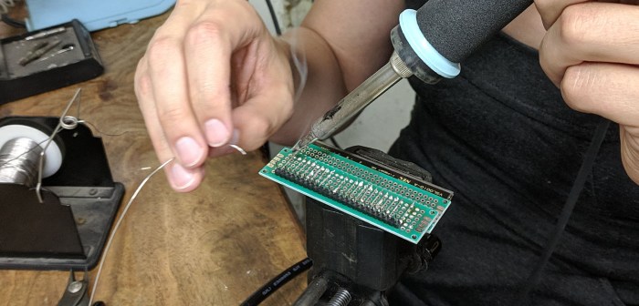
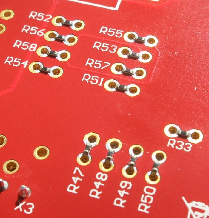
But I was not introduced to them in isolation – I saw them on the Curiosity board and in this context their purpose was immediately obvious: a link between pins on the PIC socket and the peripheral options built on that board. If I wanted to change which pins connected to which peripherals, I would not have to cut traces on the circuit board, I just had to un-solder the zero ohm resistor. Then I can change the connection on the board by soldering to the empty through-holes placed on the PCB for that purpose.

This was an illuminating “Oh that makes sense!” introduction to zero ohm resistors.

Reading the PIC32MX1XX Datasheet As A PIC16F18345 User

A review of the Hackaday Superconference 2017 “camera badge” hardware provided adequate orientation but no lightning strike of project inspiration. Today I did find the project page for last year’s Supercon badge as well as a summary page of some things people have created with the 2016 badge. People have done some really cool things with that badge serving as foundation. I’m feeling intimidated but also determined to keep trying to see what I can devise.

Today’s tactic: Dive into the data sheet for the Microchip control unit at the heart of the 2017 badge, the PIC32MX170F256D. No matter what else happens, it would be good to have an overview of what the chip can and can’t do. I was also hoping that a review of the data sheet will unveil something about the chip that would inspire a project. Since I’ve already read the PIC16F18345 data sheet back-to-back, I hoped the familiarity with Microchip conventions will give me a head start.

The first surprise was the size (length) of the data sheet. Only 344 pages when the much simpler PIC16F18345 chip had a 491 page document. It didn’t take long for me to figure out why, since every feature section started the same way: a disclaimer that the data sheet was only the summary and tells me I need to do more reading if I want the details.

OnlyASummary

Well, that explains the size! For my purposes today, it’s no big deal. In fact it is helpful since the summaries mean I don’t have to press “Page Down” as often.

There are some comfortable commonality with the PIC16F18345 I’m familiar with: Timers and comparators. Digital I/O and analog input (ADC.) Communication via SPI, I2C, UART. And all these peripheral modules are mapped into a memory space so everything is accessed via memory reads and writes. And finally: a big focus on power management.

There are some differences that I might miss in the PIC32MX1XX:

  • PWM seems to have gone missing, unless there is a much more advanced component that can serve similar purposes but I don’t recognize it as such.
  • I/O pins are much less powerful. The PIC16F can handle up to 50mA on any single I/O pin and up to 250mA total. The PIC32MX can only handle 15mA per pin with 200mA total.
  • Narrower voltage range: Unlike the super flexible and relaxed PIC16F that is happy to run with anything from 2.3V to 5.5V, the PIC32MX prefers to stay within 2.3V to 3.6V. The maximum is listed as 4.0V, so it might be dicey to run this thing on a single rechargeable lithium cell – the nominal voltage is 3.7V but a fully charged cell might be up to 4.2V.

The PIC32MX uses a different instruction set (MIPS32 M4K) and that’s no surprise. I expect to be mostly isolated from this fact by writing in C and letting the XC compiler worry about the instruction set. The PIC32MX also requires more support circuitry. Whereas the PIC16F can literally connect directly to a battery and it’ll start running. Again I’m mostly isolated in this case because the camera badge is already built for me and all the support components are already on board.

And now, on to the things that might be interesting. I started with the title description: “32-bit Microcontrollers (up to 256 KB Flash and 64 KB SRAM) with Audio and Graphics Interfaces, USB, and Advanced Analog

The first thing to catch my eye: USB, backed by this promising-sounding bullet point on the cover page: “USB 2.0-compliant Full-speed OTG controller“. USB OTG would let us plug-in USB peripherals and greatly expand the possibilities of what we can do. Alas, my hopes were dashed when page 2 clarified that USB OTG is only on the PIC32MX2XX series and absent on the PIC32MX1XX we have on the camera badge. So that’s out.

The “Advanced Analog Features” bullet items seem to mostly center around support for capacitive touch sensing, mostly around their “mTouch” design. Since their reference implementation involves copper traces and plates on a printed circuit board, that won’t be directly applicable to me. But perhaps this type of support circuitry can be hacked into something fun.

I have yet to explore the world of audio electronics, so sadly the audio interface features are mostly gibberish to me. I had higher hopes for the “Graphics Interfaces” side of that claim and… I came up empty-handed. There’s nothing that obviously said “graphics” to me on the feature set. The closest thing I can find is the PMP (Parallel Master Port) peripheral which is good for talking to display panels, and is indeed already employed on the camera badge to drive the 128×128 OLED screen.

So in the category of “stuff that the chip can do, but isn’t already being used” the best candidate at the moment is the analog circuitry to support capacitive touch. Since I don’t have time for a OSH Park PCB, it’ll have to be something creative. Perhaps something as primitive as taping down loops of wire to cardboard or 3D-printed plastic parts.

The gears in the brain keep churning…