Potential Small PC Explorations

I had fun playing with the GMKtec NucBox3, an interesting and capable little PC more affordable than Intel’s NUC product line, naturally with some expected tradeoffs for its lower cost. I learned about these little PCs from a Newegg advertisement and, between the time I ordered one and its arrival, I had a failed USB external drive that I transplanted into a small form factor Dell PC. Computers in these two projects represent a spectrum that I should keep in mind for future project possibilities. Which one I buy would depend on a project’s requirements.

Intel NUC

A genuine Intel NUC would be more expensive than any of the other options below, but sometimes it’s worth spending that money. For example, if I’m building a solution that needs to be reliable, I will pay more for a brand name. Or if I want to design something that can be repeated by others, it’s easier for someone to buy an identical Intel NUC than to find, say, a GMKtec. For this reason: If my Sawppy rover ever changes over to an x86-64 PC ROS brain, the official recommended hardware will be an Intel NUC. (Supplemented with suggestions on what to look for in lower-cost alternatives like the NucBox3.)

Just Below $90

But when we’re feeling adventurous and not particularly motivated to pay for quality or consistency, we can go bargain hunting. Searching for various options, I observed a price floor somewhere in the $80-$90 range. I see an interesting hint of economic factors at play preventing things from much lower than $90, but I don’t know what they might be. (As a point of comparison, Raspberry Pi 4 8GB MSRP is $75.)

Lowest Bidder du Jour

Amazon categorized these products under: “Electronics” > “Computers & Accessories” > “Computers & Tablets” > “Desktops” > “Minis”. Sorting them by price today, I see several options right around $89, roughly 40% discount from the price of a NucBox3. To get to that price point we have to give up many things. For example, this item (*) made some notable tradeoffs:

  • Memory is half the size (4GB vs. 8GB), uses older technology (DDR3 vs. DDR4), and is soldered in never to be upgraded.
  • Storage is half the size (64GB vs 128GB), uses much slower technology (eMMC vs. SATA) and is also permanently soldered. However, it does have a 2.5″ SATA bay, which the NucBox3 does not.
  • CPU is three years older and from a different product generation (Celeron J3455 vs. J4125) and it doesn’t meet hardware requirements for Windows 11.

On the upside, it still meets all my hard requirements for robot brain: 64-bit CPU running x86-64/amd64 instruction set, gigabit Ethernet port, small, lightweight, and might run on battery power. Depending on future project requirements, I may choose these tradeoffs in favor of a <$90 bargain.

Buying Refurbished

Looking at inexpensive PCs on Amazon, I saw a lot of refurbished units. Clicking around a few listings, I learned Amazon had set up an entire department. “Amazon Renewed” is dedicated to refurbished products of all kinds, not just computers. I should definitely keep this in mind as an option. Given my personal experience, I’d restrict my search to refurbished Dell products from their corporate line. Which would still leave me with very many options. Check out these guys, each offered at a few bucks under $90:

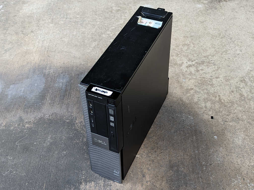
  • Optiplex 3040 Micro Desktop (*) are bigger than an Intel NUC, but tiny compared to anything else. Skimming Dell’s manual, I see a 2.5″ SATA bay inside. I also see what looks like a M.2 slot on a picture of its mainboard, but M.2 isn’t called out in the manual as a storage option. I see a gigabit Ethernet port and it accepts power from a DC barrel jack, so there’s a possibility it can be persuaded to run on battery power.
  • Optiplex 790 USFF Desktop (*) are significantly larger. Packing an optical drive on top of a 2.5″ drive bay and AC power supply. No robot battery power for this machine, but dual 2.5″ drives are possible via an optical drive caddy. This could work for TrueNAS replication target if my storage drive is a high capacity 2.5″ laptop hard drive.
  • Optiplex 3020 SFF Slim Desktop (*) is a successor to the Optiplex 960 I repurposed to a TrueNAS replication target, with at least one 3.5″ drive bay and one optical drive bay. This would be my default choice if I need to build another replication target machine.

What if I want a parallel port for LinuxCNC? Sadly, that’s an uncommon enough request I can’t filter on Amazon. But when it comes to refurbished small Dell PCs, Amazon Renewed is not the only game in town. There are plenty of other vendors like PC Liquidations, who offers filtering by parallel port. Resulting in a list of refurbished Dell Optiplex with parallel port starting at, you guessed it, a few dollars under $90. All good options if I want to dedicate a cheap PC to a task, which usually also requires me to set up automatic software updates.


(*) Disclosure: As an Amazon Associate I earn from qualifying purchases.

Good First Impressions of GMKtec NucBox3

It was fun to poke around internal hardware of a tiny PC I wanted to investigate for use as a robot brain. This GMKtec NucBox3 I ordered off Amazon (*) is a more affordable variation on the Intel NUC formula, and its price (significantly lower than Intel’s own NUC) makes me more willing to experiment with it.

Decent PC for Windows 11 Home

But before I take any risk with nonstandard usage, I should verify it worked as advertised. The 128GB SATA SSD came installed with Windows 11 Home edition build 21H2. Upon signing in with my Microsoft account, it started the update process to build 22H2. I assumed the machine came with a license of Windows either embedded in the hardware or otherwise registered. Windows 11 control panel “Activation state” says “Windows is activated with a digital license linked to your Microsoft account” which I found to be ambiguous. I shrugged because I plan to use it as ROS brain and, if so, I’m likely to run Ubuntu instead of Windows. And if I wipe the SATA drive with a fresh installation of Windows 11, it sounds like I can log in with my Microsoft account and retrieve its license.

The more informative aspect of Windows sign-in and registration is letting me get a feel of the machine in its default configuration. All hardware drivers are in place with no question marks in device manager. Normal user interface tasks were responsive and never frustrating, which is better than certain other budget Windows computers I’ve tried. A NucBox3 is a perfectly competent little Windows box for light duty computer use.

One oddity I found with the NucBox3 was the lack of a power-up screen letting me change boot behavior with a keypress. When a PC first powers up, there’s typically a prompt telling me to press F12 to enter a menu to select a boot device, or DEL to enter system setup, etc. Not on a NucBox3, though: we always boot directly into Windows. The only way I found to enter hardware menu was from within Windows: under “Settings”/”System”/”Recovery” we can choose “Advanced startup” to boot into a special Windows menu, where I can select “Advanced Options” and choose “UEFI Firmware Settings”. This is expected to be an infrequent activity most users would never do, so I guess it’s OK for the process to be a convoluted.

UEFI Menu

Once I got into UEFI menu for NucBox3 I was surprised by how many options are listed. Far more than any branded (Dell, etc) computer I’ve seen and even more than hobbyist-focused motherboards.

Some of these options like “Debug Configuration” almost feel like they weren’t supposed to ship in a final product. My hypothesis is that I’m looking at the default full menu of options for a manufacturer using this AMI (American Megatrends, Inc) UEFI firmware. Maybe the manufacturer was expected to trim it down as appropriate for their product, and maybe nobody bothered to do that.

Under the “Chipset” menu we have device configuration for many peripherals absent from this device. They’re marked [Disabled] but the menu option didn’t even need to be here. The final line was also the most surprising: a selection for resistors on I2C buses. On one hand, I’ve never seen a PC’s I2C hardware exposed in any user-visible form before. On the other hand, if I can figure out where SDA/SCL lines are on this motherboard, maybe I can really have some fun. Why bother with a Raspberry Pi or even an ESP32 to bridge I2C hardware if I can attach them directly to this PC?

Ubuntu Server

But all those shiny lights in UEFI menus were just a distraction. What I really want right now is to control boot sequence so I can boot from a USB flash drive to install Ubuntu Server 22.04 LTS. I found I could do it from the “Boot” section of UEFI menu. Ubuntu Server was installed, it worked, and that was no surprise. A computer competent at a full Windows 11 GUI rarely has a problem with text-based network-centric Ubuntu Server, and indeed I had no problems here. For a ROS brain I would want gigabit networking, all four CPU cores, RAM, storage, and USB peripherals. They are all present and accounted for, even sleep mode if I want to put a robot to sleep.

Variable Input Voltage

The next experiment was to see if this computer is tolerant of variable DC supply voltage. On paper it requires 12V DC and the supplied AC adapter was measured at 12.27V DC. I could buy a boost/buck converter that takes a range of input voltages and output a steady 12V (*) but it would be more efficient to run without such conversion if I could get away with it. Since the NucBox3 used a standard 5.5mm OD barrel jack for DC power input, it was easy to wire it up to my bench power supply. I found it was willing to boot up and run from 10VDC to 12.6VDC, the operating voltage range of 3S LiPo battery packs.

Good ROS Brain Candidate

This little computer successfully ran Ubuntu Server on (simulated) battery power. It handily outperforms the Dell 11 3180 I previously bought as ROS brain candidate and is much more compact for easy integration on robot chassis. Bottom line, I have a winner on my hands here!

I’m glad that Newegg advertisement made me aware of an entire ecosystem of inexpensive small PCs. I need to keep this product category in mind as candidates for potential future projects. I have many options to consider, depending on a project’s needs.


(*) Disclosure: As an Amazon Associate I earn from qualifying purchases.

Looking Inside GMKtec NucBox3

I thought the GMKtec NucBox3 looked interesting (at least on paper) as candidate ROS brain, so I ordered one (*) for a closer look despite some skepticism. All pictures on that Amazon listing look perfect, I suspected they were all 3D computer renders instead of photos of an actual product. There’s a chance the actual product looked very different from the listing.

The good news: the product is real and for the most part, as depicted in the listing. I find good fit and finish on its plastic enclosure. There is one downside: fingerprints show up very clearly. I had to wipe down the case pretty aggressively for these pictures and I still see greasy smudges. Well, at least you know these aren’t renders! One instance where oily fingerprint smudges are a feature, not a bug.

I see two brass heat-set inserts on the bottom of the case which will be useful for mounting this little box somewhere. They look very small but this is a small lightweight box so it would probably suffice.

Here we also see where actual product differed from product listing rendering. The company website page for NucBox3 showed an access panel to upgrade memory or storage.

But there’s no such access panel on the real thing, and it’s not clear how to get inside without one. Documents in the box consisted of a minimal warranty card in the box and no instruction manual. No matter, the lack of a convenient access panel or a manual shall not deter me from getting inside for a look.

Hiding fasteners under glued-on rubber feet is a common and effective technique. These four fasteners are not symmetrical so, even though the box is a square, we need to remember correct orientation to reinstall.

Without a convenient access door for upgrades, I wasn’t sure what else would differ from listing picture. I was afraid memory and storage would be soldered-in parts, but I was relieved to find they were standard DDR4 RAM and M.2 2280 SSD as advertised. They’re just a tiny bit harder to access without the panel.

Judging by its M.2 keys, we have the option to upgrade this factory-installed SATA M.2 SSD to a higher-performing NVMe M.2 SSD if needed.

What appears to be empty threaded holes (marked with circles) are actually used to secure the CPU heatsink from the other side. (There’s a fourth one under RAM module and not visible in this image.) Four fasteners (marked with squares) secure the motherboard and must be removed to proceed.

The headphone jack protrudes into the enclosure, so we must tilt the mainboard from the opposite side for removal. But we have to be careful because we are limited by length of WiFi antenna wires.

A block of foam keeps WiFi antenna connectors in place, peeling it back allowed the connectors to be released. The antennae themselves appear to be thin sheets glued to the top of the case, similar to what I’ve salvaged from laptops. How securely were they held? I don’t know. I didn’t try to peel them off.

Freed of WiFi wires, I could flip the mainboard over to see a big heatsink surrounded by connectors. As chock-full of connectors as this product already is, I was surprised to see that there are still several provisions for even more connectors on the circuit board. I’m also very fascinated by connectors used here for USB3, HDMI, and DisplayPort. I usually see them oriented flat against the circuit board as typical of laptop mainboards, but without design pressure to be thin, these connectors are standing upright. This is a tradeoff to fit more connectors on the edge of a circuit board, but each connector must go deeper to obtain the necessary mechanical strength to withstand use.

Looking in from the side, the heatsink appears to have a flat bottom. This is good news if I want to mount a different heatsink on this board, possibly with a fan. The flat bottom means I don’t have to worry about sticking out to make thermal contact with other chips or have to cut a hole to clear protrusions. If I want to mount to the same holes, I will have to drill four holes which unfortunately are irregularly spaced but not an insurmountable challenge. All that said, I’m more likely to just point a fan at this heatsink if heat proves to be a problem.

Using this computer as robot brain also means running it on battery power. Nominal power requirements are listed as 12V up to 3A. My voltmeter measured the factory power adapter output at 12.27V. But what can this thing tolerate? I found this chip directly behind the DC power barrel jack, but a search for DC3905 WK1MEG (or WX1MEG) didn’t turn up anything definitive. Texas Instruments has a LP3905 and Analog inherited Linear Technology’s LT3905. Both chips are designed for DC power handling, but neither footprint matches this chip. This might not even be the power management chip, I’m only guessing based on its proximity to the DC barrel jack.

As far as I know, the highest voltage requirement on this PC are USB ports at 5V. On the assumption that nothing on this machine actually needs 12V, then all power conversion are buck converters to lower voltage levels. If true, then this little box should be OK running directly on 3S LiPo power (Three lithium-polymer battery cells in series) which would range from 12.6V fully charged to 11.1V nominal to 10V low power cutoff. I’ll use the power brick that came in the box to verify everything works before testing my battery power hypothesis.


(*) Disclosure: As an Amazon Associate I earn from qualifying purchases.

SATA Optical to 2.5″ Drive Adapter

I dusted off an old Dell Optiplex 960 for use as my TrueNAS replication backup target. The compact chassis had a place for my backup storage 8TB 3.5″ HDD extracted from a failed USB enclosure, which is good. But I also need a separate drive for Ubuntu operating system, and that’s where I ran into problems. There was an empty 3.5″ bay and a SATA data socket available on the motherboard, but the metal mounting bracket was missing, and power supply had no more SATA power plugs.

As an alternative plan, I thought I would repurpose the optical drive’s location. Not just its SATA data and power plugs, but I could also repurpose physical mounting bracket with an optical drive shaped caddy for a 2.5″ SATA drive. (*) It wasn’t a perfect fit but that was my own fault for ordering the wrong size.

Examining the caddy after I opened its package, I saw this oddly bent piece of sheet metal. Comparing against the DVD drive, I don’t think it’s supposed to bend like that. I can’t tell if it was damaged at the factory or during shipping, either way metal was thin and easy to bend back into place.

Also comparing against the DVD drive, I realized I bought the wrong size. It didn’t occur to me to check to see if there were multiple different sizes for laptop DVD drives. I bought a 9.5mm thick caddy (*) when I should have bought something thicker possibly this 12.7mm thick unit.(*) Oh well, I have this one in hand now and I’m going to try to make it work.

To install this caddy in an Optiplex 960 chassis, I need to reuse the sheet metal tray currently attached to the DVD drive.

One side fit without problems, but the other side didn’t fit due to mismatched height. This is my own fault.

There’s a mismatch in width as well, I’m not sure this was my fault. I understand the different form factors to be the same width so this part should have lined up. Oh well, at least it is easier to deal with a ~1mm too narrow adapter because one ~1mm too wide wouldn’t fit at all.

There were slots to take the DVD drive’s faceplate. This is for aesthetics so we don’t leave a gaping hole, the eject button wouldn’t work as it is no longer a DVD drive. Unfortunately, faceplate mounting slots didn’t match up, either. This might also be a function of the wrong height, but I’m skeptical. I ended up using the generic faceplate that came with the caddy.

Forcing everything to fit results in a caddy mounted crookedly.

Which resulted in a crooked facade.

Aesthetically speaking this is unfortunate, I should have bought a taller caddy (*) but functionally this unit works fine. The SSD is securely mounted in the caddy, which is now securely mounted to the chassis. And even more importantly, SATA power and data communication worked just fine, allowing me to install Ubuntu Server 22.04 LTS on an old small SSD inside the caddy. And about that old SSD… freeing it up for use turned out to be its own adventure.


(*) Disclosure: As an Amazon Associate I earn from qualifying purchases.

Dusting Off Dell Optiplex 960 SFF PC

After two years of use, my USB3 external 8TB backup drive stopped responding as an external disk. I took apart its enclosure and extracted a standard 3.5″ hard disk drive which seems OK in perfunctory testing. In order to continue using it for TrueNAS replication backup, I’ll need another enclosure. I briefly contemplated getting an USB3 SATA enclosure that takes 3.5″ drives (*) but I decided to use an entire computer as its enclosure: I have an old Dell Optiplex 960 SFF (small form factor) PC collecting dust and it would be more useful as my TrueNAS replication backup machine.

Dell’s Optiplex line is aimed at corporate customers, which meant it incorporated many design priorities that weren’t worth my money to buy new. But those designs also tend to live well past their first lives, and I have bought refurbished corporate Dells before. I’ve found them to be sturdy well-engineered machines that, on the secondhand market, is worth a small premium over generic refurbished PCs.

There’s nothing garish with exterior appearance of an Optiplex, just the computer equivalent of professional office attire. This particular machine is designed to be a little space-efficient box. Office space costs money and some companies decide compactness is worth paying for. Building such a compact box required using parts with nonstandard form factors. For a hobbyist like me, not being able to replace components with generic standard parts is a downside. For the corporate IT department with a Dell service contract, the ease of diagnosis and servicing is well worth the tradeoff.

This box is just as happy sitting horizontally as vertically, with rubber feet to handle either orientation.

Before it collected dust on my shelf, this computer collected dust on another maker’s shelf. I asked for it sometime around the time I started playing with LinuxCNC. I saw this computer had a built-in parallel port, so I would not need an expansion card. (Or I can add a card for even more control pins.) The previous owner said “Sure, I’m not doing anything with it, take it if you will do cool things with it.” Unfortunately, my LinuxCNC investigation came to a halt due to pandemic lockdown and I lost access to that space. TrueNAS replication target may not be as cool as my original intention for this box, but at least it’s better than collection dust.

Even though the chassis is small, it has a lot of nice design features. The row of “1 2 3 4” across the front are diagnostics LEDs. They light up in various combinations during initial boot-up so, if the computer fails to boot corporate IT tech support can start diagnosing failure before even opening up the box.

Which is great, because opening up the box might be hindered by a big beefy lock keeping the side release lever from sliding.

And if we get past the lock and open the lid, we trip the chassis intrusion detection switch. I’ve seen provision for chassis intrusion detection in my hobbyist-grade motherboards, but I never bothered to add an actual intrusion switch to any of my machines. Or a lock, for that matter.

Once opened I find everything is designed to be worked on without requiring specific tools. This chassis accommodates two half-height expansion cards: One PCI and one PCI-Express. On my PCs, expansion endplates are held by small Philips-head screws. On this PC, endplates are retained by this mechanism.

A push on the blue button releases a clamp for access to these endplates.

Adjacent to those expansion slots is a black plastic cage for 3.5″ Hard drive.

Two blue metal clips release the cage to flip open, allowing access to the hard drive. This drive was intended to be the only storage device hosting operating system plus all data. I plan to install my extracted 8TB backup storage drive in this space, which needs to be a separate drive from the operating system drive, so I need to find another space for a system drive.

Most of the motherboard is visible after I flipped the HDD cage out of the way. I see three SATA sockets. One for the storage HDD, one for the DVD drive, and an empty one I can use for my system drive. Next to those slots is a stick of DDR2 RAM. (I’m quite certain Corsair-branded RAM is not original Dell equipment.) Before I do anything else with this computer, I will need to replace the CR2032 coin cell timekeeping battery.

A push on the blue-stickered sheet metal button released the DVD drive. Judging by scratches, this DVD drive has been removed and reinstalled many times.

Putting the DVD drive aside, I can see a spare 3.5″ drive bay underneath. This was expected because we could see a 3.5″ blank plate in the front of this machine, possibly originally designed for a floppy disk drive. The good news is that this bay is empty and available, the bad news is that a critical piece of hardware is missing: This chassis is designed to have a sheet metal tray for installing a 3.5″ drive, which is not here.

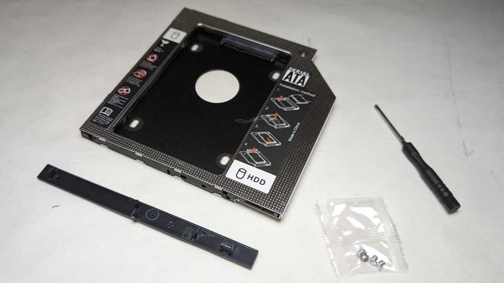
I can probably hack around the missing bracket with something 3D-printed or even just double-sided tape. But even if I could mount a small SSD in here, there are no spare SATA power connector available for it. This is a problem. I contemplated repurposing the DVD drive’s power and data cables for a SSD and found adapters cables for this purpose. (*) But under related items, I found a product I didn’t even know existed: an optical-to-hard drive adapter (*) that doesn’t just handle the power and data connectors, it is also a mechanical fit into the optical drive’s space!


(*) Disclosure: As an Amazon Associate I earn from qualifying purchases.

Window Shopping: GMKtec NucBox3 Mini PC

A Newegg advertisement sent me down a rabbit hole of tiny little desktop PCs with full x86-64 processors. I knew about Intel’s NUC, but I hadn’t realized there was an entire product ecosystem of such small form factor machines built by other manufacturers. The one that originally caught my attention was distributed by several different companies under different names, I haven’t figured out who made it. But that exploration took me to GMKtec which is either their manufacturer, or a distributor with a sizable collection of similar products built by different manufacturers. The product that originally caught my attention is listed as their “NucBox5” (company website listing and Amazon link *) but I actually found their “NucBox3” (company website listing and Amazon link *) to be a more interesting candidate for my Sawppy Rover’s ROS brain. Both products have a Gigabit Ethernet wired networking port that I demand for resistance against RF interference, but beyond that, their respective designs differ wildly:

First the bad news: the NucBox 3 has an older CPU, the Celeron J4125 instead of the Celeron N5105. But comparing them side-by-side, it looks like I’d be giving up less than 10% of peak CPU performance. There is a huge (~50%) drop in GPU performance, but that doesn’t matter to Sawppy because most of the time its brain wouldn’t even have a screen attached.

A longer list of good stuff balances out the slower CPU:

  • RAM on the NucBox 3 is a commodity DDR4 laptop memory module. That can be easily upgraded if needed, unlike the soldered-in memory on the NucBox 5.
  • They both use M.2 SSDs for storage, but the NucBox 3 accommodates popular 2280 form factor instead of a less common 2245 size used by NucBox 5.
  • The SSD advantage was possible because NucBox 3 has a different shape: is wider and deeper than a NucBox 5, but not as tall. Designed for installation on a VESA 100×100 mount, it will be easier to bolt onto a rover chassis.
  • Officially, NucBox 3 is a fan-less passively cooled machine whereas the NucBox 5 has a tiny little cooling fan inside. (Which I expect to be loud, as tiny cooling fans tend to be.) Given that these are both 10W chips, I doubt NucBox 3 has a more effective cooling solution, I think it is more likely that the design just lets the chip heat up and throttle itself to stay within thermal limits. This would restrict its performance in stock form, but it also means it’ll be easy for me to hack up a quiet cooling solution if necessary.
  • NucBox 5 accepts power via USB-C, which is getting easier and easier to work with. I foresaw no problems integrating it with battery power onboard a Sawppy rover. But the NucBox 3 has a generic 5.5mm barrel jack for DC input power, and I think that’ll be even easier.

A NucBox3 costs roughly 80% of a NucBox5 for >90% of the performance, plus all of the designed tradeoff listed above are (I feel) advantages in favor of the NucBox3. I’m sold! I placed an order (*) and look forward to playing with it once it arrives.


(*) Disclosure: As an Amazon Associate I earn from qualifying purchases.

Window Shopping: Mystery Mini PC of Many Names

An interesting item came to my attention via Newegg marketing mailing list for discounts: an amazingly tiny Windows PC. My attention was captured by listing picture showing its collection of hardware ports. Knowing the size of an Ethernet port and HDMI port we can infer this is an itty-bitty thing. Newegg’s specific sale item was generically named “Mini PC” with an asking price of $200. I’m not entirely sure the thing is real: all the images look perfect enough I couldn’t tell if they’re 3D renderings or a highly retouched product photos.

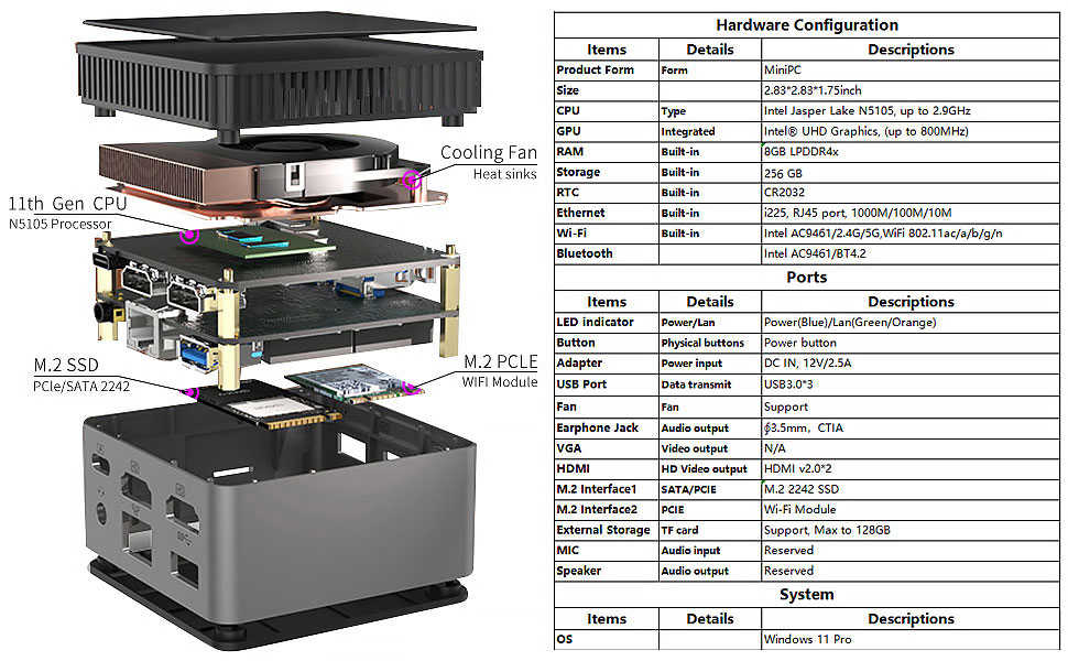
I looked at the other listings by the same vendor “JOHNKANG” and saw several other generically named devices ranging from laptops to external monitors. There were no other similar products, so I think JOHNKANG is a distributor and not the manufacturer of this palm-sized wonder. If JOHNKANG is a US distributor for such merchandise, I guessed they probably have an Amazon listing as well. Sure enough, they have it listed on Amazon also at $200(*) at time of writing. Unlike the Newegg listing, the Amazon listing included this exploded-view diagram showing internals and capabilities.

That’s… pretty darned good for $200! With an Intel Celeron N5105 processor, I see a machine roughly equivalent to capabilities of a budget laptop but without the keyboard, screen, or battery. Storage size is serviceable at 256GB and can be swapped out with another M.2 SSD, though in a less common 2242 format which is shorter than the popular 2280. Its 8GB of RAM are soldered and not easily expandable, but 8GB is more than sufficient for this price point.

A few features distinguish this tiny PC from equivalent-priced laptops, starting with its dual HDMI port where laptops only have one. That might be important for certain uses, but I’m more interested in its wired Gigabit Ethernet port and that it runs on USB-C power input. This machine appears to check off all of my requirements for a candidate Sawppy Rover brain. It’s a pretty good candidate for running ROS slotting just below an Intel NUC in capability but compensates for that with a lower price and smaller physical size. Heck, at this size it is starting to compete with Raspberry Pi and might even fit in a Micro Sawppy.

I found no make or model number listed, which is consistent with a distributor that really doesn’t want us to comparison shop against anyone else who might be distributing the same product for less money. If I want hard details, I might have to buy one and look over the hardware for hints as to who built it. Still, searching for “Mini PC” and “MiniPC” with N5105 CPU found this eBay listing of a used unit with Rateyuso branding. Then I found this AliExpress listing with ZX01 as model name. That AliExpress listing is a mess, showing pictures of several other different mini PCs. Not confidence inspiring and definitely turned me off of buying from that vendor. However, the “ZX01” model name was useful because it led me to this page, which linked to a Kickstarter project that has apparently been taken down due to intellectual property dispute.

Performing an image search using the suspiciously perfect picture/render found the GMKtec Nucbox5(*) which appears to be the same product but with “GMKtec” stamped on top. Looking at the Amazon storefront for GMKtec (*) I see many other small form factor PCs without any family resemblance between their industrial designs. My hypothesis is that GMKtec is a distributor as well, but they have built up a collection of products from different manufacturers and that’s why they all look different. I thought this was encouraging. It implies experience and knowledge with the ecosystem of tiny PCs, offering a breadth of products each making a different tradeoff. I looked over their roster and found one more to my taste.


(*) Disclosure: As an Amazon Associate I earn from qualifying purchases.

High Power 600W Power Supply (HP1-J600GD-F12S)

Along with the “keyboard is broken” laptop, I was also asked to look into a mid-tower PC that would no longer turn on. I grabbed a power supply I had on hand and plugged it into the motherboard, which happily powered up. Diagnosis: dead power supply. I bought a new power supply for the PC to bring it back to life, now it’s time to take apart the dead power supply to see if I can find anything interesting. Could it be as easy as a popped circuit breaker or a blown fuse?

According to the label, the manufacturer has the impossibly unsearchable name of “High Power”. Fortunately, the model number HP1-J600GD-F12S is specific enough to find a product page on the manufacturer’s site. The exact model string also returned a hit for a power supply under Newegg’s house brand Rosewill, implying the same device was sold under Newegg’s own name. Amusingly, Newegg’s Rosewill product listing included pictures with “High Power” embossed on the side.

If there is a user-replaceable fuse or a user-accessible circuit breaker, they should be adjacent to the power socket and switch. I saw nothing promising at the expected location or anywhere else along the exterior.

Which meant it was time to void the warranty.

Exterior enclosure consisted of two pieces of sheet metal each bent into a U shape and held together with four fasteners. Once pried apart, I had to cut a few more zip-ties holding the cooling fan power wire in place before I could unplug it to get a clear view at the interior. Everything looks clean. In fact, it looked too clean — either this computer hadn’t been used very much before it blew, or it lived in a location with good air filtration to remove dust.

Still on the hunt for a circuit breaker or a fuse, I found the standard boilerplate fuse replacement warning. Usually, this kind of language would be printed immediately adjacent to a user-serviceable fuse. But getting here required breaking the warranty seal and none of the adjacent components looked like a fuse to me.

Disassembly continued until I could see the circuit traces at the bottom of the board. Getting here required some destructive cutting of wires, so there’s no bringing this thing back online. Perhaps someone with better skills could get here nondestructively but I lacked the skill or the motivation to figure things out nicely. I saw no obviously damaged components or traces on this side, either. But more importantly, now I could see that 120V AC line voltage input wire is connected to a single wire. That must lead to the fuse.

Turning the board back over, I see the line voltage input wire (brown) connected to a black wire that led to a cylinder covered in heat-shrink tubing and held in place by black epoxy. The shape of that cylinder is consistent with a fuse. The heat-shrink and epoxy meant this is really not intended to be easily replaced.

Once unsoldered, I could see the electronic schematic symbol for fuse printed on the circuit board. The “F” in its designation “F1” is consistent with “Fuse”, as do the amperage/voltage ratings listed below. This fuse is a few centimeters away from the caution message I noticed earlier, which was farther away than I had expected. My multi-meter showed no continuity across this device, so indeed the fuse has blown. I cut off the heat-shrink hoping to see a burnt filament inside a glass tube, but this fuse didn’t use a glass tube.

I started this teardown wondering if it was “as easy as a popped circuit breaker or a blown fuse”. While it was indeed a blown fuse, a nondestructive replacement would not have been easy. I don’t know why the fuse on this device was designed to be so difficult to access and replace, but I appreciate it is far better to blow a fuse than for a failing power supply to start a fire.

Windows PC Keyboard Beeps Instead of Types? Turn Off “Filter Keys”

A common side effect of technical aptitude is the inevitable request “Can you help me with my computer?” Whether this side effect is an upside or downside depends on the people involved. Recently I was asked to help resurrect a computer that had been shelved due to “the keyboard stopped working.”

Before I received the hardware, I was told the computer was an Asus T300L allowing me to do a bit of research beforehand. This is a Windows 8 era touchscreen tablet/laptop convertible along the lines of a Microsoft Surface Pro or the HP Split X2. This added a twist: the T300L keyboard base not only worked while docked, but it could also continue working as a wireless keyboard + touchpad when separated from the screen. This could add a few hardware-related variables for me to investigate.

When I was finally presented with the machine, I watched the owner type their Windows login password using the keyboard. “Wait, I thought you said the keyboard didn’t work?” “Oh, it works fine for the password. It stops working after I log in.”

Ah, the hazard of imprecision of the English language. When I was first told “keyboard doesn’t work” my mind went to loose electrical connections. And when I learned of the wireless keyboard + touchpad base, I added the possibility of wireless settings (device pairing, etc.) I had a hardware-oriented checklist ready and now I can throw it all away. If the keyboard worked for typing in Windows password, the problem is not hardware.

Once the Windows 8 desktop was presented, I could see what “keyboard stopped working” meant: every keypress resulted in an audible beep but no character typed on screen. A web search with these symptoms found this Microsoft forum thread titled “Keyboard Beeps and won’t type” with the (apparently common) answer to check Windows’ Ease of Access center. I made my way to that menu (as the touchscreen worked fine) and found that Filter Keys were turned on.

Filter Keys is a feature that helps users living with motor control challenges that result in shaky hands. This could result in pressing a key multiple times when they only meant to press a key once or jostling adjacent keys during that keypress. Filter Keys slow the computer’s keyboard response, so they only register long and deliberate presses as a single action. Rapid tap and release of a key — which is what usually happens in mainstream typing action — are ignored and only a beep is played. Which is great, if the user knew how to use Filter Keys and intentionally turned it on.

In this case, nobody knows how this feature got turned on for this computer, but apparently it was not intentional. They didn’t recognize the symptoms of Filter Keys being active. Lacking that knowledge, they could only communicate their observation as “the keyboard stopped working.” I guess that description isn’t completely wrong, even if it led me down the wrong path in my initial research. Ah well. Once Filter Keys were turned off, everything is fine again.

MageGee Wireless Keyboard (TS92)

In the interest of improving ergonomics, I’ve been experimenting with different keyboard placements. I have some ideas about attaching keyboard to my chair instead of my desk, and a wireless keyboard would eliminate concerns about routing wires. Especially wires that could get pinched or rolled over when I move my chair. Since this is just a starting point for experimentation, I wanted something I could feel free to modify as ideas may strike. I looked for the cheapest and smallest wireless keyboard and found the MageGee TS92 Wireless Keyboard (Pink). (*)

This is a “60% keyboard” which is a phrase I’ve seen used two different ways. The first refers to physical size of individual keys, if they were smaller than those on a standard keyboard. The second way refers to the overall keyboard with fewer keys than the standard keyboard, but individual keys are still the same size as those on a standard keyboard. This is the latter: elimination of numeric keypad, arrow keys, etc. means this keyboard only has 61 keys, roughly 60% of standard keyboards which typically have 101 keys. But each key is still the normal size.

The lettering on these keys are… sufficient. Edges are blurry and not very crisp, and consistency varies. But the labels are readable so it’s fine. The length of travel on these keys are pretty good, much longer than a typical laptop keyboard, but the tactile feedback is poor. Consistent with cheap membrane keyboards, which of course this is.

Back side of the keyboard shows a nice touch: a slot to store the wireless USB dongle so it doesn’t get lost. There is also an on/off switch and, next to it, a USB Type-C port (not visible in picture, facing away from camera) for charging the onboard battery.

Looks pretty simple and straightforward, let’s open it up to see what’s inside.

I peeled off everything held with adhesives expecting some fasteners to be hidden underneath. I was surprised to find nothing. Is this thing glued together? Or held with clips?

I found my answer when I discovered that this thing had RGB LEDs. I did not intend to buy a light-up keyboard, but I have one now. The illumination showed screws hiding under keys.

There are six Philips-head self-tapping plastic screws hidden under keys distributed around the keyboard.

Once they were removed, keys assembly easily lifted away to expose the membrane underneath.

Underneath the membrane is the light-up subassembly. Looks like a row of LEDs across the top that shines onto a clear plastic sheet acting to diffuse and direct their light.

I count five LEDs, and the bumps molded into clear plastic sheet worked well to direct light where the keys are.

I had expected to see a single data wire consistent with NeoPixel a.k.a. WS2812 style of individually addressable RGB LEDs. But label of SCL and SDA implies this LED strip is controlled via I2C. If it were a larger array I would be interested in digging deeper with a logic analyzer, but a strip of just five LEDs isn’t interesting enough to me so I moved on.

Underneath the LED we see the battery, connected to a power control board (which has both the on/off switch and the Type-C charging port) feeding power to the mainboard.

Single cell lithium-polymer battery with claimed 2000mAh capacity.

The power control board is fascinating, because somebody managed to lay everything out on a single layer. Of course, they’re helped by the fact that this particular Type-C connector doesn’t break out all of the pins. Probably just a simple voltage divider requesting 5V, or maybe not even that! I hope that little chip at U1 labeled B5TE (or 85TE) is a real lithium-ion battery manage system (BMS) because I don’t see any other candidates and I don’t want a fiery battery.

The main board has fewer components but more traces, most of which led to the keyboard membrane. There appears to be two chips under blobs of epoxy, and a PCB antenna similar to others I’ve seen designed to work on 2.4GHz.

With easy disassembly and modular construction, I think it’ll be easy to modify this keyboard if ideas should strike. Or if I decide I don’t need a keyboard after all, that power subsystem would be easy (and useful!) for other projects.


(*) Disclosure: As an Amazon Associate I earn from qualifying purchases.

Old OCZ SSD Reawakened and Benchmarked

In the interest of adding 3.5″ HDD bays to a tower case, along with cleaning up wiring to power them, I installed a Rosewill quad hard drive cage where a trio of 5.25″ drive bays currently sit open and unused. It mostly fit. To verify that all drive cage cable connections worked with my SATA expansion PCIe card (*) I grabbed four drives from my shelf of standby hardware. When installing them in the drive cage, I realized I made a mistake: one of the drives was an old OCZ Core Series V2 120GB SSD that had stopped responding to its SATA input. I continued installation anyway because I thought it would be interesting to see how the SATA expansion card handled a nonresponsive drive.

Obviously, because today intent was to see an unresponsive drive, Murphy’s Law stepped in and foiled the plan: when I turned on the computer, that old SSD responded just fine. Figures! I don’t know if there was something helpful in the drive cage, or the SATA card, or if something was wrong with the computer that refused to work with this SSD years ago. Whatever the reason, it’s alive now. What can I do with it? Well, I can fire up the Ubuntu disk utility and get some non-exhaustive benchmark numbers.

Average read rate 143.2 MB/s, write 80.3 MB/s, and seek of 0.22 ms. This is far faster than what I observed by using the USB2 interface, so I was wrong earlier about the performance bottleneck. Actual performance is probably lower than this, though. Looking at the red line representing write performance, we can see it started out strong but degraded at around 60% of the way through the test and kept getting worse, probably the onboard cache filling up. If this test ran longer, we might get more and more of the bottom end write performance of 17 MB/s.

How do these numbers compare to some contemporaries? Digging through my pile of hardware, I found a Samsung ST750LM022. This is a spinning-platter laptop hard drive with 750GB capacity.

Average read 85.7 MB/s, write 71.2 MB/s, and seek of 16.77 ms. Looking at that graph, we can clearly see degradation in read and write performance as the test ran. We’d need to run this test for longer before seeing a bottom taper, which may or may not be worse than the OCZ SSD. But even with this short test, we can see the read performance of a SSD does not degrade over time, and that SSD has a much more consistent and far faster seek time.

That was interesting, how about another SSD? I have an 120GB SSD from the famed Intel X25-M series of roughly similar vintage.

Average read 261.2 MB/s, write 106.5 MB/s, seek 0.15 ms. Like the OCZ SSD, performance took a dip right around the 60% mark. But after it did whatever housekeeping it needed to do, performance level resumed at roughly same level as earlier. Unlike the OCZ, we don’t see as much of a degradation after 60%.

I didn’t expect this simple benchmark test to uncover the full picture, as confirmed after seeing this graph. By these numbers, the Intel was around 30% better than the OCZ. But my memory says otherwise. In actual use as a laptop system drive, the Intel was a pleasure and the OCZ was a torture. I’m sure these graphs are missing some important aspects of their relative performance.

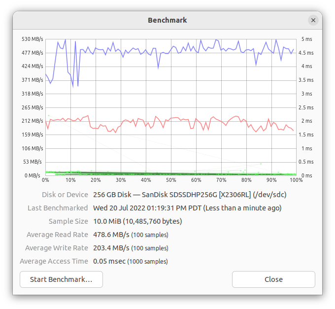
Since I had everything set up anyway, I plugged in a SanDisk SSD that had the advantage of a few years of evolution. In practical use, I didn’t notice much of a difference between this newer SanDisk and the old Intel. How do things look on this benchmark tool?

Average read 478.6 MB/s, write 203.4 MB/s, seek 0.05 ms. By these benchmarks, the younger SanDisk absolutely kicked butt of an older Intel with at least double the performance. But that was not borne out by user experience as a laptop drive, it didn’t feel much faster.

Given that the SanDisk benchmarked so much faster than the Intel (but didn’t feel that way in use) and OCZ benchmarked only slightly worse than the Intel (but absolutely felt far worse in use) I think the only conclusion I can draw here is: Ubuntu Disk Utility built-in benchmarking tool does not reflect actual usage. If I really wanted to measure performance details of these drives, I need to find a better disk drive benchmarking tool. Fortunately, today’s objective was not to measure drive performance, it was only to verify all four bays of my Rosewill drive cage were functional. It was a success on that front, and I’ll call it good for today.


(*) Disclosure: As an Amazon Associate I earn from qualifying purchases.

Rosewill Hard Disk Drive Cage (RSV-SATA-Cage-34)

Immediately after my TrueNAS CORE server power supply caught fire, I replaced it with a spare power supply I had on hand. This replacement had one annoyance: it had fewer SATA power connectors. As a short-term fix, I dug up some adapters from the older CD-ROM style power connectors to feed my SATA drives, but I wanted a more elegant solution.

The ATX tower case I used for my homebuilt server had another issue: it had only five 3.5″ hard drive bays for my six-drive array. At the moment it isn’t a problem, because the case had two additional 2.5″ laptop sized hard drive mount points and one drive in my six-drive array was a smaller drive salvaged from an external USB drive which fits in one bay. The other 2.5″ bay held the SSD boot drive for my TrueNAS CORE server. I did not want to be constrained to using a laptop drive forever, so I wanted a more elegant solution to this problem as well.

I found my elegant solution for both problems in a Rosewill RSV-SATA-Cage-34 hard drive cage. It fits four 3.5″ drives into the volume of a trio of 5.25″ drive bays, which is present on my ATX tower case and currently unused. This would solve my 3.5″ bay problem quite nicely. It will also solve my power connector problem, as the cage used a pair of CD-ROM style connectors for power. A circuit board inside this cage redistributes that power to four SATA power connectors.

First order of business was to knock out the blank faceplates covering the trio of 5.25″ bays.

Quick test fit exposed a problem: the drive cage is much longer than a CD-ROM drive. For the case to sit at the recommended mounting location for 5.25″ peripherals, drive cage cooling fan would bump up against the ATX motherboard power connector. This leaves very little room for the four SATA data cables and two CD-ROM power connectors to connect. One option is to disconnect and remove the cooling fan to give me more space, but I wanted to maintain cooling airflow, so I proceeded with the fan in place.

Given the cramped quarters, there would be no room to connect wiring once the cage was in place. I pulled the cage out and connected wires while it was outside the case, then slid it back in.

It is a really tight fit in there! Despite my best effort routing cables, I could not slide the drive cage all the way back to its intended position. This was as hard as I was willing to shove, leaving the drive cage several millimeters forward of its intended position.

As a result, the drive cage juts out beyond case facade by a few millimeters. Eh, good enough.

Radeon HD 7950 Video Card (MSI R7950-3GD5/OC BE)

This video card built around a Radeon HD 7950 chip is roughly ten years old. It is so outdated, nobody would pay much for a used unit on eBay. Not even at the height of The Great GPU Shortage. I’ve been keeping it around as a representative for full sized, dual-slot PCIe video cards as I played with custom-built PC enclosures. But I now have other video cards that I can use for the purpose, so this nearly-teenager video card landed on the teardown bench.

Most of its exterior surface is covered by a plastic shroud, but the single fan intake is no longer representative of modern GPUs with two or three fans.

Towards the center of this board is a metal bracket for fastening a heat sink that accounted for most of the weight of this card. In the upper left corner are auxiliary PCIe power supply sockets. The circuit board has provision for a 6-pin connector adjacent to an 8-pin connector, even though only two 6-pin connectors are soldered to this board. Between those connectors and the GPU itself, I see six (possibly seven) sets of components. I infer these are power-handling parts working in parallel to feed a power-hungry chip.

This was my first 4K UHD capable video card, which I used via the mini-DisplayPort connectors on the right. As I recall, the HDMI port only supported up to 1080p Full HD and could not drive a 4K display. Finally, a DVI port supported all DVI capabilities (not all of them do): analog VGA on its DVI-A pins, plus dual-link DVI-D for driving larger displays. I don’t recall if the DVI-D plug could output 4K UHD, but I knew it went beyond 1080p Full HD by driving a 2560×1600 monitor.

The plastic shroud was held by six plastic screws to PCB and two machine screws to metal plate. Once those eight fasteners were removed, shroud came off easily. From here we get a better look at the PCIe auxiliary power connectors on the top right, and the seven sets of capacitors/inductors/etc. that work in parallel to handle power requirements of this chip.

Four small machine screws held the fan shroud to the heat sink. Fan label indicates this fan consumes up to 6 Watts (12V 0.5A) and I recall it can get move a lot of air at full blast. (Or at least, gets very loud trying.) It appears to be a four-wire fan which I only recently understood how to control if I wanted. Visible on the fan’s underside is a layer of fine dust that held on, despite a blast of compressed air I used to clean out dust bunnies before this teardown.

Some more dust had also clung on to these heat sink fins. It seems like a straightforward heat sink with stamped sheet metal fins on an aluminum base, no heat pipes like what we see on many modern GPUs. But if it is all aluminum, and there are no heat pipes, it should be lighter weight than it is.

Unfastening four machine screws from the X-shaped rear bracket allowed me to remove the heat sink, and now we can see the heat sink has a copper core for heat distribution. That explains the weight.

The GPU package is a high-density circuit board in its own right, hosting not just the GPU die itself but also a large collection of supporting components. Based on the repeated theme of power handling, I guess these little tan rectangles are surface mount capacitor arrays, but they might be something else.

Here’s a different angle taken after I cleaned up majority of thermal paste. An HD 7950 is a big silicon die sitting on a big package.

When I cleaned all thermal paste off the heatsink, I was surprised at its contact surface. It seems to be the direct casting mold surface texture with no post-processing. For CPU heatsinks, I usually see a precision machined flat surface, either milling or grinding. Low-power/low-cost devices may skip such treatment for their heatsinks, but I don’t consider this GPU as either low power or low cost. I know this GPU dissipated heat on par with a CPU, yet there was no effort for a precision flat surface to maximize heat transfer.

I think this is a promising module for reuse. Though in addition to the lack of precision flat surface, there’s another problem that the copper core is slightly recessed. The easiest scenario for reuse is to find something that sticks up ~2mm above its surrounding components, but not by more than the 45x45mm footprint of this GPU. This physical shape complicates my top two ideas for reuse: (1) absolute overkill cooling for a Raspberry Pi, or (2) retrofit active cooling to the passively-cooled HP Split X2. If I were to undertake either project, I’d have to add shims or figure out how to remove some of the surrounding aluminum.

Disable Sleep on a Laptop Acting as Server

I’ve played with different ways to install and run Home Assistant. At the moment my home instance is running as a virtual machine inside KVM hypervisor. The physical machine is a refurbished Dell Latitude E6230 running Ubuntu Desktop 22.04. Even though it will be running as a server, I installed the desktop edition for access to tools like Virtual Machine Manager. But there’s a downside to installing the desktop edition for server use: I did not want battery-saving features like suspend and sleep.

When I chose to use an old laptop like a server, I had thought its built-in battery would be useful in case of power failure. But I hadn’t tested that hypothesis until now. Roughly twenty minutes after I unplugged the laptop, it went to sleep. D’oh! The machine still reported 95% of battery capacity, but I couldn’t use that capacity as backup power.

The Ubuntu “Settings” user interface was disappointingly useless for this purpose, with no obvious ability to disable sleep when on battery power. Generally speaking, the revamped “Settings” of Ubuntu 22 has been cleaned up and now has fewer settings cluttering up all those menus. I could see this as a well-meaning effort to make Ubuntu less intimidating to beginners, but right now it’s annoying because I can’t do what I want. To the web search engines!

Looking for command-line tools to change Ubuntu power saving settings brought me to many pages with outdated information that no longer applied to Ubuntu 22. My path to success started with this forum thread on Linux.org. It pointed to this page on linux-tips.us. It has a lot of ads, but it also had applicable information: systemd targets. The page listed four potentially applicable targets:

  • suspend.target
  • sleep.target
  • hibernate.target
  • hybrid-sleep.target

Using “systemctl status” I could check which of those were triggered when my laptop went to sleep.

$ systemctl status suspend.target
○ suspend.target - Suspend
     Loaded: loaded (/lib/systemd/system/suspend.target; static)
     Active: inactive (dead)
       Docs: man:systemd.special(7)

Jul 21 22:58:32 dellhost systemd[1]: Reached target Suspend.
Jul 21 22:58:32 dellhost systemd[1]: Stopped target Suspend.
$ systemctl status sleep.target
○ sleep.target
     Loaded: masked (Reason: Unit sleep.target is masked.)
     Active: inactive (dead) since Thu 2022-07-21 22:58:32 PDT; 11h ago

Jul 21 22:54:41 dellhost systemd[1]: Reached target Sleep.
Jul 21 22:58:32 dellhost systemd[1]: Stopped target Sleep.
$ systemctl status hibernate.target
○ hibernate.target - System Hibernation
     Loaded: loaded (/lib/systemd/system/hibernate.target; static)
     Active: inactive (dead)
       Docs: man:systemd.special(7)
$ systemctl status hybrid-sleep.target
○ hybrid-sleep.target - Hybrid Suspend+Hibernate
     Loaded: loaded (/lib/systemd/system/hybrid-sleep.target; static)
     Active: inactive (dead)
       Docs: man:systemd.special(7)

Looks like my laptop reached the “Sleep” then “Suspend” targets, so I’ll disable those two.

$ sudo systemctl mask sleep.target
Created symlink /etc/systemd/system/sleep.target → /dev/null.
$ sudo systemctl mask suspend.target
Created symlink /etc/systemd/system/suspend.target → /dev/null.

After they were masked, the laptop was willing to use most of its battery capacity instead of just a tiny sliver. This should be good for several hours, but what happens after that? When the battery is almost empty, I want the computer to go into hibernation instead of dying unpredictably and possibly in a bad state. This is why I left hibernation.target alone, but I wanted to do more for battery health. I didn’t want to drain the battery all the way to near-empty, and this thread on AskUbuntu led me to /etc/UPower/UPower.conf which dictates what battery levels will trigger hibernation. I raised the levels so the battery shouldn’t be drained much past 15%.

# Defaults:
# PercentageLow=20
# PercentageCritical=5
# PercentageAction=2
PercentageLow=25
PercentageCritical=20
PercentageAction=15

The UPower service needs to be restarted to pick up those changes.

$ sudo systemctl restart upower.service

Alas, that did not have the effect I hoped it would. Leaving the cord unplugged, the battery dropped straight past 15% and did not go into hibernation. The percentage dropped faster and faster as it went lower, too. Indication that the battery is not in great shape, or at least mismatched with what its management system thought it should be doing.

$ upower -i /org/freedesktop/UPower/devices/battery_BAT0
  native-path:          BAT0
  vendor:               DP-SDI56
  model:                DELL YJNKK18
  serial:               1
  power supply:         yes
  updated:              Fri 22 Jul 2022 03:31:00 PM PDT (9 seconds ago)
  has history:          yes
  has statistics:       yes
  battery
    present:             yes
    rechargeable:        yes
    state:               discharging
    warning-level:       action
    energy:              3.2079 Wh
    energy-empty:        0 Wh
    energy-full:         59.607 Wh
    energy-full-design:  57.72 Wh
    energy-rate:         10.1565 W
    voltage:             9.826 V
    charge-cycles:       N/A
    time to empty:       19.0 minutes
    percentage:          5%
    capacity:            100%
    technology:          lithium-ion
    icon-name:          'battery-caution-symbolic'

I kept it unplugged until it dropped to 2%, at which point the default PercentageAction behavior of PowerOff should have occurred. It did not, so I gave up on this round of testing and plugged the laptop back into its power cord. I’ll have to come back later to figure out why this didn’t work but, hey, at least this old thing was able to run 5 hours and 15 minutes on battery.

And finally: this laptop will be left plugged in most of the time, so it would be nice to limit charging to no more than 80% of capacity to reduce battery wear. I’m OK with 20% reduction in battery runtime. I’m mostly concerned about brief blinks of power of a few minutes. A power failure of 4 hours instead of 5 makes little difference. I have seen “battery charge limit” as an option in the BIOS settings of my newer Dell laptops, but not this old laptop. And unfortunately, it does not appear possible to accomplish this strictly in Ubuntu software without hardware support. That thread did describe an intriguing option, however: dig into the cable to pull out Dell power supply communication wire and hook it up to a switch. When that wire is connected, everything should work as it does today. But when disconnected, some Dell laptops will run on AC power but not charge its battery. I could rig up some sort of external hardware to keep battery level around 75-80%. That would also be a project for another day.

ESP8266 Controlling 4-Wire CPU Cooling Fan

I got curious about how the 4 wires of a CPU cooling fan interfaced with a PC motherboard. After reading the specification, I decided to get hands-on.

I dug up several retired 4-wire CPU fans I had kept. All of these were in-box coolers bundled with various Intel CPUs. And despite the common shape and Intel brand sticker, they were made by three different companies listed at the bottom line of each label: Nidec, Delta, and Foxconn.

I will use an ESP8266 to control these fans running ESPHome, because all relevant code has already been built and ready to go:

  • Tachometer output can be read with the pulse counter peripheral. Though I do have to divide by two (multiply by 0.5) because the spec said there are two pulses per fan revolution.
  • The ESP8266 PWM peripheral is a software implementation with a maximum usable frequency of roughly 1kHz, slower than specified requirement. If this is insufficient, I can upgrade to an ESP32 which has hardware PWM peripheral capable of running 25kHz.
  • Finally, a PWM fan speed control component, so I can change PWM duty cycle from HomeAssistant web UI.

One upside of the PWM MOSFET built into the fan is that I don’t have to wire one up in my test circuit. The fan header pins were wired as follows:

  1. Black wire to circuit ground.
  2. Yellow wire to +12V power supply.
  3. Green wire is tachometer output. Connected to a 1kΩ pull-up resistor and GPIO12. (D6 on a Wemos D1 Mini.)
  4. Blue wire is PWM control input. Connected to a 1kΩ current-limiting resistor and GPIO14. (D5 on Wemos D1 Mini.)

ESPHome YAML excerpt:

sensor:
  - platform: pulse_counter
    pin: 12
    id: fan_rpm_counter
    name: "Fan RPM"
    update_interval: 5s
    filters:
      - multiply: 0.5 # 2 pulses per revolution

output:
  - platform: esp8266_pwm
    pin: 14
    id: fan_pwm_output
    frequency: 1000 Hz

fan:
  - platform: speed
    output: fan_pwm_output
    id: fan_speed
    name: "Fan Speed Control"

Experimental observations:

  • I was not able to turn off any of these fans with a 0% duty cycle. (Emulating pulling PWM pin low.) All three kept spinning.
  • The Nidec fan ignored my PWM signal, presumably because 1 kHz PWM was well outside the specified 25kHz. It acted the same as when the PWM line was left floating.
  • The Delta fan spun slowed linearly down to roughly 35% duty cycle and was roughly 30% of full speed. Below that duty cycle, it remained at 30% of full speed.
  • The Foxconn fan spun down to roughly 25% duty cycle and was roughly 50% of the speed. I thought it was interesting that this fan responded to a wider range of PWM duty cycles but translated that to a narrower range of actual fan speeds. Furthermore, 100% duty cycle was not actually the maximum speed of this fan. Upon initial power up, this fan would spin up to a very high speed (judged by its sound) before settling down to a significantly slower speed that it treated as “100% duty cycle” speed. Was this intended as some sort of “blow out dust” cleaning cycle?
  • These are not closed-loop feedback devices trying to maintain a target speed. If I set 50% duty cycle and started reducing power supply voltage below 12V, the fan controller will not compensate. Fan speed will drop alongside voltage.

Playing with these 4-pin fans were fun, but majority of cooling fans in this market do not have built-in power transistors for PWM control. I went back to learn how to control those fans.

CPU Cooling 4-Wire Fan

Building a PC from parts includes keeping cooling in mind. It started out very simple: every cooling fan had two wires, one red and one black. Put +12V on the red wire, connect black go ground, done. Then things got more complex. Earlier I poked around with a fan that had a third wire, which proved to be a tachometer wire for reading current fan speed. The obvious follow-up is to examine cooling fans with four wires. I first saw this with CPU cooling fans and, as a PC builder, all I had to know was how to plug it in the correct orientation. But now as an electronics tinkerer I want to know more details about what those wires do.

A little research found the four-wire fan system was something Intel devised. Several sources cited URLs on http://FormFactors.org which redirects to Intel’s documentation site. Annoyingly, Intel does not make the files publicly available, blocking it with a registered login screen. I registered for a free account, and it still denied me access. (The checkmark next to the user icon means I’ve registered and signed in.)

Quite unsatisfying. But even if I can’t get the document from official source, there are unofficial copies floating around on the web. I found one such copy, which I am not going to link to because the site liberally slathered the PDF with advertisements and that annoys me. Here is the information on the title page which will help you find your own copy. Perhaps even a more updated revision!

4-Wire Pulse Width Modulation
(PWM) Controlled Fans
Specification
September 2005
Revision 1.3

Reading through the specification, I learned that the four-wire standard is backwards compatible with three-wire fans as those three wires are the same: GND, +12V supply, and tachometer output. The new wire is for a PWM control signal input. Superficially, this seems very similar to controlling fan speed by PWM modulating the +12V supply, except now the power supply stays fixed at +12V and the PWM MOSFET is built into the fan. How is this better? What real-world problems are solved by using an internal PWM MOSFET? The spec did not explain.

According to spec, the PWM control signal should be running at 25kHz. Fan manufacturers can specify a minimum duty cycle. Fan speed for duty cycle less than the minimum is open for interpretation by different implementations. Some choose to ignore lower duty cycles and stay running at minimum, some interpret it as a shutoff signal. The spec forbids pull-up or pull-down resistor on the PWM signal line external to the fan, but internal to the fan there is a pull-up resistor. I interpret this to mean that if the PWM line is left floating, it will be pulled up to emulate 100% duty cycle PWM.

Reading the specification gave me the theory of operation for this system, now it’s time to play with some of these fans to see how they behave in practice.

OCZ Core Series V2 120GB SSD (OCZSSD2-2C120G)

My first SSD was a Patriot WARP V.2 32GB SSD. It not quite the bleeding edge, that “V.2” signified a revision that solved some issues in the first wave. Early experience with my first SSD was amazing enough for me to look for a larger 120GB unit to gain a little more elbow room in day-to-day use. They both represented early technology with flaws that needed solving before SSD became long-term reliable. I didn’t know that when I bought them, but it was certainly made clear as their performance degraded over a few years and then dying entirely when they no longer showed up as SATA drives when plugged them in. I took apart the first Patriot drive, now it’s time for the second OCZ drive.

Since they were both built around the JMF602 controller and arrived on market around the same time, I expected them to both utilize a JMF602 reference design. Before I opened up this SSD, I expected the circuit board to look identical to the smaller Patriot, just with higher capacity flash memory chips.

I found I was wrong when I opened up the case, this drive used a very different circuit board layout. This design placed the JMF602 at the center, and I don’t see an obvious debug header. There is still a connector adjacent to the SATA data port and it is populated on this drive: a USB mini-B socket that lets this SSD act as a USB flash drive.

Four more flash chips live on the other side of this board, again in a different layout compared to the Patriot drive. They seem to have the same production information sticker, but that might be some sort of industry standard sticker.

Thanks to the USB port, I could still access this drive even though the SATA port no longer enumerates. It is only an USB 2.0 connection, but I don’t think that is a constraint. Write performance has degraded to an atrocious level on this drive. Here I’m copying a single large ISO file to the drive. 25MB/sec throughput and a response time of nearly 500ms are well below limits of USB2.

Read throughput is only slightly better at nearly 40MB/sec and a 20ms read response time is significantly faster but still not great. Since this drive still works via USB, for now I’ll spare it the hot air treatment I performed to the Patriot. But given this level of performance I’m not sure if I can do anything useful with it.

Patriot WARP V.2 32GB SSD (PE32GS25SSD)

When the cost of flash memory dropped low enough for consumer-level solid state drives to come to market, it was a time when multicore multi-gigahertz processors sit mostly idle waiting for data to be fetched from a spinning platter hard drive. SSDs resolved that performance bottleneck and provided a huge boost to overall system performance. But like all revolutionary technology, early implementations had some serious teething issues. Some problems required operating system support like TRIM to solve, which didn’t show up until later.

In those pre-TRIM days, the most affordable consumer-level SSD were built around a JMF602 controller. It helped make SSD affordable, but without TRIM and related functions, those drives weren’t durable. My first two SSDs used JMF602 and both drives died within two years of use. When I plug them into a computer’s SATA port, they no longer enumerate as devices as if they weren’t plugged in at all.

I forgot I had kept those two drives until I found them in my pile of old computer hardware. I might as well open them up before I dispose of them. I don’t expect to see much: just a circuit board inside a 2.5″ form factor metal case. But I was curious if those two circuit boards would be identical: it is fairly common for multiple manufacturers to use the same reference implementation and sell basically identical devices.

First up is Patriot’s WARP V.2 with a paltry 32GB capacity, model PE32GS25SSD.

I found the expected single circuit board inside. The infamous JMF602 chip amongst multiple Samsung flash chips. I see a row of four vias on the lower right edge resembling an unpopulated debug header. (Not that I’d know how to debug this thing.) In the lower left, adjacent to the SATA data connector, is an unpopulated connector blocked off by the metal case. We’ll see this again later.

Four more Samsung flash chips reside on the other side of the circuit board.

I now remember why I kept the drive even after it failed: I had personal data on this drive when stopped responding. Even though it doesn’t enumerate as a SATA device for me, I was worried that the data could still be recovered. Perhaps through that debug header, or possibly a SATA diagnostic tool could unlock it.

Making data really difficult to recover is easy with a spinning platter hard drive: I would open it up to expose those shiny platters. Everyday household dust would render those data surfaces unreadable except to maybe the NSA. But at the time I didn’t know how to perform similar data destruction with SSDs. I had contemplated drilling a hole through each flash chip, but now that I have a hot air rework station, I decided to remove all 16 flash chips from the board. If someone wants to steal my data, they’ll have to decipher how my data was spread across these chips and do a lot of soldering. I may still drill a hole through one of those chips just for curiosity, but first I want to compare and contrast this drive with my second SSD based on the same JMF602 controller.

Computer Cooling Fan Tachometer Wire

When I began taking apart a refrigerator fan motor, I expected to see simplest and least expensive construction possible. The reality was surprisingly sophisticated, including a hall effect sensor for feedback on fan speed. Seeing it reminded me of another item on my to-do list: I’ve long been curious about how computer cooling fans report their speed through that third wire. The electrical details haven’t been important to build PCs, all I needed to know was to plug it the right way into a motherboard header. But now I want to know more.

I have a fan I modified for a homemade evaporator cooler project, removing its original motherboard connector so I could power it with a 12V DC power plug. The disassembled connector makes it unlikely to be used in future PC builds and also makes its wires easily accessible for this investigation.

We see an “Antec” sticker on the front, but the actual manufacturer had its own sticker on the back. It is a DF1212025BC-3 motor from the DF1212BC “Top Motor” product line of Dynaeon Industrial Co. Ltd. Nominal operating power draw is 0.38A at 12V DC.

Even though 12V DC was specified, the motor spun up when I connected 5V to the red wire and grounded the black wire. (Drawing only 0.08 A according to my bench power supply.) Probing the blue tachometer wire with a voltmeter didn’t get anything useful. Oscilloscope had nothing interesting to say, either.

To see if it might be an open collector output, I added a 1kΩ pull-up resistor between the blue wire and +5V DC on the red wire.

Aha, there it is. A nice square wave with 50% duty cycle and a period of about 31 milliseconds. If this period corresponds to one revolution of the fan, that works out to 1000/31 ~= 32 revolutions per second or just under 2000 RPM. I had expected only a few hundred RPM, so this is roughly quadruple my expectations. If this signal was generated by a hall sensor, it would be consistent with multiple poles on the permanent magnet rotor.

Increasing the input voltage to 12V sped up the fan as expected, which decreased the period down to about 9ms. (The current consumption went up to 0.22 A, lower than the 0.38 A on the label.) The fan is definitely spinning at some speed far lower than 6667 RPM. I think dividing by four (1666 RPM) is in the right ballpark. I wish I had another way to measure RPM, but regardless of actual speed the key observation today is that the tachometer wire is an open-collector output that generates a 50% duty cycle square wave whose period is a function of the RPM. I don’t know what I will do with this knowledge yet, but at least I now know what happens on that third wire!

[UPDATE: After buying a multichannel oscilloscope, I was able to compare fan tachometer signal versus fan behavior and concluded that a fan tachometer wire signals two cycles for each revolution. Implying this fan was spinning at 3333 RPM which still seems high.]

Miscellaneous Notes on HP Stream 7 Installation

My old HP Stream 7 can now run around the clock on external power, once I figured out I needed to disable its battery drivers. Doing so silenced the module that foiled my previous effort. (It would raise an alert: “the tablet has run far longer than the battery capacity could support” and shut things down.) Ignoring that problematic module, remaining drivers in the same large Intel chipset driver package allowed the machine to step down its power consumption. From ten watts to under two watts, even with the screen on. (Though at minimum brightness.) Quite acceptable and I’m quite certain I’ll repurpose this tablet for a project in the future. In the meantime, I wanted to jot down some notes on this hardware as reference.

The magic incantation to get into boot select menu (getting into BIOS, reinstalling operating system, and other tools) is to first shut down the tablet. While holding [Volume Down], hold [Power] until the HP logo is visible. Release power immediately or else it might trigger the “hold power for four seconds to shut off” behavior. (This is very annoying.) The boot select menu should then be visible along with on-screen touch input to navigate without a keyboard.

There are many drivers on the HP driver downloads site. Critical for optimized power consumption — and majority of onboard hardware — is the “Intel Chipset, Graphics, Camera and Audio Driver Pack”. I also installed the “”Goodix Touch Controller Driver” so the touchscreen would work, but be warned: this installer has a mix of case-sensitive and case-insensitive code which would fail with a “File Not Found” error if the directory names got mixed up. (/SWSetup/ vs /swsetup/)

The available drivers are for Windows 8 32-bit (what the machine came with) and Windows 10 32-bit (what it is successfully running now.) The machine is not able to run 64-bit operating system despite the fact its Intel Atom Z3735G CPU is 64-bit capable. I don’t know exactly what the problem is, but when I try to boot into 64-bit operating system installer (true for both Windows 10 and Ubuntu) I get the error screen

The selected boot device failed. Press <Enter> to Continue.
[Ok]

Which reminds me of another fun fact: this machine has only a single USB micro-B port. In order to use USB peripherals, we need a USB OTG adapter. Which is good enough for a bootable USB drive for operating system installation… but then I need to press [Ok] to continue! The usual answer here is to use an USB hub so I could connect both the bootable OS installer and a keyboard. There’s actually no guarantee this would work: it’s not unusual for low-level hardware boot USB to support only root-level devices and not hubs. Fortunately, this tablet supported a hub to connect multiple USB devices allowing bootable USB flash driver for operating system installation to coexist with USB input devices to navigate a setup program.

I’ll probably need some or all of these pointers the next time I dig this tablet out of my pile of hardware. For now, I return it to the pile… where I noticed an unpleasant surprise.