Broken Source is not Open Source

After attending Elecia White’s “On Cats and Typing” talk, I felt a little more motivated to look into robots. The robot arm used in her demo was the MeArm by Mime Industries. It is built out of commodity micro servos and laser-cut acrylic. I looked at it and thought I could get one up and running on my own. It is sold as a self-assembled kit but in the spirit of open source, people are also allowed to laser-cut their own pieces using the open-sourced DXF file available via Github.

Or at least that was the theory.

In practice, the DXF doesn’t work. Inkscape couldn’t load it. CorelDRAW couldn’t load it. Onshape couldn’t load it. Fusion 360 – from Autodesk, the people who created AutoCAD which is where DXF came from – couldn’t load it.

MeArm Broken

Well, that was disappointing.

Google results confirm I’m not alone. I found many reports of people failing to get this DXF to work for them, and not a single success story. Of course, there’s a little selection bias here: people who encounter no problems rarely go on the internet to announce they had no problems. But I would have expected a few of the forum posts from people having problems to get some positive responses, and I didn’t find any of those.

This is frustrating. I’m unlikely to go and buy the kit when I already had most of the pieces on hand and it is in theory open source for me to make my own. It’s impossible to tell if there’s a perfectly innocent explanation or if this was done maliciously to slap on the “open source” label without actually risking any cut into sales. Whatever the explanation for why this DXF is broken, it doesn’t change the fact that it is broken. When the publicly available source file is unusable. Is it still open source?

I vote no.

Simple Circuit Board On 3D-Printed Plastic

CircuitBoard
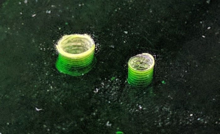
Here’s a behind-the-scenes follow-up to the LED test fixtures of the previous few posts: when we only need a simple circuit for a 3D-printed project, we can meld the two instead of using a formal circuit board. In this context “meld” is meant literally: the parts of the circuit can be heated up with the soldering iron so they melt into the 3D printer plastic.

When I built the dual-LED acrylic illumination test rig, I wanted the simplest circuit possible. It’s not something I need to be durable long-term and I wanted to be up and running with my tests as quickly as possible. The full length of a resistor and its wires are almost long enough to bridge the gap between the two sides of the fixture, so I tried to make that work.

When I started soldering all the wires together, I had planned to just leave everything dangling. But the close proximity of the soldering gun to the 3D printed PLA plastic started softening the plastic and I realized I can use this to my advantage. A few seconds with the soldering iron was all it took to heat up a wire so it can be melted into and embedded into the plastic. The resistors themselves took a little more effort, but I sunk them into the plastic as well. The LEDs had been held in place by their bent legs, which was sufficiently stable but had a tiny bit of wobble. Melting the plastic around LED legs gave us a much more secure placement.

Components melted into the plastic are no longer subject to flexing and eventually breaking from metal fatigue. Add a strip of electrical tape to guard against short circuiting to complete the quick and simple circuit to light up the test rig LEDs.

Illuminate Acrylic Edge: Test Fixture 2

After running through a few acrylic test pieces looking for the best edge illumination, I decided I need a dual fixture to allow side-by-side comparison as I swap through test pieces.

IMG_5158

Another change I made in the text fixture is to remove the aluminum foil at the bottom. While the foil may be useful to direct light, it distracts from the testing. If a particular test piece is losing light to the fixture, I don’t want that light reflected back in. I want to be able to see the failure in the form of illuminated white plastic. When there are no acrylic test pieces in the fixture, the cone of illumination is clearly visible.

IMG_5159
Test fixture #2 illuminated without acrylic test pieces.

The two sides aren’t exactly identical. One of the LED is slightly brighter than the other, and the two sides ended up with slightly different textures. But it should be good enough for our comparison purposes.

The first fixture implied that the cavity surround the LED is where we should focus our attention, so let’s try a few shapes. A square and a circle seems to differ only slightly in the brightness of the center top hot spot.

IMG_5161
Square LED cavity (left) and circular LED cavity (right)

A triangular cavity was much more interesting – all the light has been diverted from the top center, sending them off to the side. And I tried a teardrop shape just to see what would happen. The important detail to note on the teardrop is that a lot of light was lost to the fixture instead of being sent to the edges. This tells us the cavity edges should be as small as possible to push its surface right up against the LED to reduce light loss.

IMG_5162
Triangular (left) and teardrop (right)

The cavity sizes were then minimized for the next set, again testing for different shapes. A flat top to the cavity didn’t work as well as the cavity shape conforming to the LED shape.

IMG_5163
Flat top cavity (left) and conforming curve cavity (right)

But the best results came from putting a small curve in front of the point of the LED. This appears to break up the central beam and sends it to the edges like we want.

LED scatter curve

From an cost/benefit ratio perspective, this small curve is a winner. It is a very minor change to the geometry and yet it delivers significant improvement to the resulting light. When put into a larger sheet of acrylic, with greater number of internal reflections, it should do quite well. And for a little extra smoothness in illumination, we can take a piece of sandpaper and lightly roughen up the surface. Adding a frosted edge reduces the reflections somewhat, but it does help even out the overall illumination.

IMG_5165
Best illumination to date with the small curve (left) which can be further enhanced by a frosted edge (right)

These experiments have been quite informative. I look forward to applying what was learned here to future acrylic projects.

Illuminate Acrylic Edge: Goals and Test Fixture

After the surprising success of LED illumination in FreeNAS v2 enclosure, I wanted to spend some time experimenting with the concept. When searching for “acrylic edge illumination” on Google, everybody seems to be talking about positioning the LED at the edge of the acrylic sheet and lighting up the pattern of something engraved on the acrylic. My goal is the opposite: I want to place the LED in the middle of the acrylic, and I want the light to shine out to the edge of the acrylic sheet.

We start with the assumption that by default, a LED shining inside a piece of acrylic will only illuminate in the direction it is pointed.

Hotspot

Our ideal goal is to determine how to direct this light so it illuminates all the edges of the acrylic sheet, not just the direction of the LED face.

Ideal

I 3D printed a small test fixture for these experiments. It has space for a 75mm x 75mm test piece of acrylic and a LED that pokes up in the middle of that space. There’s a 10mm wide border around the test piece so I can observe the pattern of illumination beyond the edge. At the outside edge of the border, a wall to observe the intensity of illumination beyond the edge. A piece of black tape covers the direction of the viewer so the LED doesn’t overwhelm the rest of the observation. A piece of aluminum foil lines the bottom of the test fixture to reflect any light back into the acrylic.

IMG_5146

The fixture lights up as expected in the absence of any acrylic.

IMG_5147

These two experiments tested cutting grooves in the acrylic. One set had straight grooves, a second set curved. They were successful in breaking up the center top hot spot, sending some of that light elsewhere. But the light seems too concentrated on the bottom third.

IMG_5151

IMG_5152

Instead of cutting grooves, this piece tested cutting entirely through the acrylic. The circular shape does seem to disperse the light fairly well.

IMG_5149

These were interesting, but the most surprising result came from a test piece of acrylic with nothing cut in the middle. I had expected the light pattern to resemble the triangular hot spot of the LED by itself without any acrylic, but we got this:

IMG_5148

It has the same basic trend of the other light patterns in this set of experiments, which tells us the majority of the light scattering is not done by the curved/straight grooves or the circle. The feature with the largest impact is actually the small cavity surrounding the LED itself.

The fixture has been informative, but it has one problem: it is difficult to make comparisons between different test acrylic pieces. Before proceeding with investigation, the test fixture will be expanded so there are two test pieces side by side for comparison.

Acrylic Lights: Infinity Mirror

I’ve played with putting lights in my 3D-printed creations for glowing illumination effects. There were limits to what I could do with 3D printing, though, because printing with a clear filament does not result in a clear object. In contrast, acrylic is clear and works as a light guide with a lot of possibilities.

I’ve noticed a few attention-getting light effects in my acrylic projects to date, most of them created by happy accident. The acrylic box with external fixture made good use of external light. The Portable External Monitor version 2.0 was built from stacks of acrylic sheets: its fluorescent back light reflected between the layers like an infinity mirror.

PEMv2_InfLights

This effect was on my exploration to-do list for the future, but I moved it to the top of the list after seeing surprisingly good results on the FreeNAS Box v2 enclosure.

I had planned for it to have the standard PC status LEDs: one for power, and one for disk activity. The acrylic plate for motherboard mounting spacer also had two cutouts for 3mm LEDs along the center line. The red hard drive activity light is to be mounted high, and the blue power light mounted down low. The idea was for the blue light to illuminate the top edge of the plate. When there is hard drive activity, red LED will light up the center of that edge, and it should blend to purple with the power light. Both LEDs were blocked from direct view by the motherboard, so all we should see is a nice soft glow emitting from behind the motherboard.

FreeNASv2LightPlan

That was the plan, the reality was different. The red activity light worked as expected: when there is disk activity, the center of the top edge had a little red glow.

The blue LED decided to ignore my “nice soft glow” plan and put on an extravagant light show. It didn’t just light the top edge, it lit every edge of that acrylic sheet and had plenty of extra light energy to throw on the surrounding shelving.

FreeNASv2_LightsAbove

Here’s a close-up of the sideways illumination.

FreeNASv2_LightsSide

The many rays visible in the side illumination, as well as the lines making up the top illumination, indicate infinity mirror action going on inside that sheet. It wasn’t directly visible, and probably very difficult to photograph even if so. Without internal reflections, the blue light would have just gone straight up. But with the smooth surfaces and edges of the acrylic reflecting inside the sheet, the light of a single LED bounced around, found different angles, and was emitted in many more directions.

This LED illumination effect warrants further investigation. It is a happy accident that I fully intend to learn from, and put into future acrylic projects.

I want every acrylic project to look this awesome!


FreeNAS Box v2: Construction Complete

After spending an afternoon + evening at a Tux-Lab work session, I have my FreeNAS Box v2! It’s always fun to see my idea turned into reality.

FreeNASv2 Complete

The first thing I appreciated was the fact that the components are clearly visible through the acrylic panels. And even better, the messy tangle of wires are hidden behind them. This reversal from v1 is the best aesthetic change.

The other major design requirement – that both cooling fans be visibly spinning – is also present but it doesn’t have as much of an immediate aesthetic effect.

After I’ve kept it on and running overnight, I checked the temperature around the box the following morning. I think it would be neat to check thermal performance with a FLIR thermal imaging camera but lacking such toys I went with the low-tech way of putting my hands at various places around the box to feel the temperature.

The front chamber – where the CPU and motherboard reside – has a slight temperature gradient from top to bottom but overall it was relatively cool to the touch. This was expected as the CPU basically sat idle all night. It also means I won’t need to cut a hole in the front door for a direct air intake.

The rear chamber, with the power supply and both hard drives, is where most of the heat is generated. The two drives were warm to the touch signifying that they’ve been spinning all night and getting some amount of cooling to keep them from getting hot.

The power supply fan was running and the power supply case was cool to the touch. The power meter read 30W for the FreeNAS box in this steady-state idle state. This is a very light load for a 600W-rated power supply, reflected in its cool running temperature.

FreeNAS Box v2: Construction Fixture

One of the problems with FreeNAS Box v1 was that I designed it with tabs and slots to fit into each other. While it made the box easy to assemble, the slots severely weakened the structure of the box.

For FreeNAS Box v2 I avoid the tabs and slots. But I need something else in their absence to help me during construction. The answer is a fixture: Something I design along with the box that helps me build it, but not part of the end product.

Building the box will start with bonding all the major vertical pieces together. Once the cement has set hard enough for them to stand alone, the fixture pieces can be removed. The resulting assembly will then be self-supporting as the remaining pieces are attached.

The fixture pieces sit top and bottom. Pretty much where the largest horizontal pieces would eventually go, but are distinctly different from those pieces.

FreeNASv2 Fixtures.JPG
Initial assembly (gray) with assembly fixture (yellow)

The top fixture has two slots for holding two of the vertical sheets of acrylic. We’ve already established such slots are bad for the structural strength of the end product, but it’s perfectly OK (and quite useful) to have them in a fixture.

Both the top and bottom fixture have round cutouts in the corners and in the mid-span T-joint so that they stay clear of any extraneous acrylic cement that might leak out. This way we avoid accidentally cementing the fixture to the product.

Each of the fixture is made of two layers of acrylic, a main layer and a secondary layer whose shapes helps keep the box pieces in place. The small round circles visible in the picture is sized for M4 screws to fasten the fixture layers together. Using screws instead of acrylic cement allows us to later disassemble the fixture and recycle the pieces as scrap acrylic in future projects.

FreeNAS Box v2: Additional Goals

We’ve just established all the problems exposed by the v1 prototype that we want to address for v2. In addition to those issues, we also want v2 to cover a few things that are no fault of the v1 prototype.

First one is relatively obvious: actually build a complete and usable case. I knew I was trying new ideas in v1 and that something will go wrong, so it wasn’t really complete. Even if everything went right (I knew it wouldn’t) I would have had to build a v2. For one example, I didn’t bother to design an access door.

We then have a few separate items that relate to improving space efficiency.

When I placed v1 on the shelf where I expected to keep my FreeNAS box, it wasted a few inches between the back and the wall due to the angle of the power cable. I want to rearrange things so that the back of the box can sit flat against the wall.

Cooling path in v1 started with air intakes on the bottom of the case. This was part of the tribute to the Apple PowerMac G4 cube, but functionally unnecessary while consuming vertical space.

Also contributing to the vertical space consumption was pointing all the ports downwards, like the PowerMac G4 cube. This made the ports difficult to access. It would be good to align the direction of all the plugs, so power and network cables can be in parallel.

Out of all the requirements listed here and in the previous post, the greatest impact was the “make sure all fans are visible for easy verification they are spinning” goal. It meant rearranging the components so both fans face forward. This made for an interesting design challenge as it is against common convention of computer case design. Once I got that set up, the configuration was then further refined in Fusion 360 to satisfy all the remaining requirements until we have this: my FreeNAS Box v2.

FreeNASv2

FreeNAS Box v1 Problems

FreeNAS Box v1 was a good learning project for acrylic construction. Here are the issues with v1 I want to address for the next version.

  1. Non-orthogonal joints: The laser cutter only cuts right angle edges. v1 had a few joints that were impossible to cement because the edges didn’t align at right angles.
  2. Tab and slot construction: To help align joints, I designed v1 with tabs to fit into slots I had also cut into their mating surfaces. While this made the box easy to build, it destroyed durability of the end product. The sharp corners of the slots are where acrylic starts cracking under stress. I had known about the dangers of sharp internal corners, but I thought acrylic cement would bond everything together eliminating the weak point. This idea has now been proven false.

    FreeNAS1_Cracks
    Stress cracks that started at corners of slots.
  3. Unappealing tangle of wires: The v1 box design placed all of the wires up front, which turned out to look pretty ugly, and all the components (hard drives and the motherboard) were hidden under the mess.

    FreeNASv1
    Yes, there’s a computer under the tangle of wires.
  4. Difficult access to components: Besides looking bad, the mess of wires up front also blocks access to everything else. It would be difficult to perform maintenance such as replacing drives if they fail.
  5. Cooling fans vulnerable to jamming: The wiring paths were such that, if some wires should misbehave and bend slightly out of position, they would impinge upon the blades of cooling fans stopping them from turning.

    FreeNASv1_Flaw
    Several wires in this bundle poked into the fan grill where it does not belong.
  6. Cooling fans are out of sight: Compounding the problem of blocked fans is the fact that despite the clear acrylic exterior, it was not easy to notice the fans were blocked.

I had to physically build FreeNAS Box v1 before I knew known any of the above are problems. Some I had thought about and didn’t think would be a problem, the others I just hadn’t thought about at all.

Internal Fixture for Acrylic Box

Continuing my self-examination for assumptions that might be holding me back, I started thinking about the fact that all the fixtures I’ve built so far for the box exercise are external to the box. This seemed like an obvious approach – tools are almost always outside of the object that the tools are working on.

But while working with various fixtures, I’ve occasionally wished for something inside the box to brace against. At various points I thought about building an internal component to mate against the external fixture, but for one reason or another that hasn’t happened. So let’s try that now.

Internal Fixture


It turned out far more successfully than I had expected. When the fixture is on the outside of the box, my hands performing assembly had to work inside the tight internal volume. But when the fixture sits inside, my hands have far more freedom to move around outside and everything is easier to do. The assembly of a test box with this fixture was far smoother than any of the test box assemblies built with previous fixtures.

Since it worked so well, I went digging into the pile of scrap acrylic and cut panels for more boxes. While putting together these boxes by hand, I thought about how I’d automate the various tasks involved. The good news is that the fixture is no longer the biggest blocker, other aspects of box assembly now demand some problem-solving time.

Task #1: Peeling the protective paper backing off the laser-cut pieces of acrylic. At the moment this is a very tedious task that demands strong fingernails and luck. If we want to make a production line of a laser-cut acrylic product, we need a solution.

Task #2: Dispensing Weld-On 16 acrylic cement. Acrylic cements like Weld-On 4, with low viscosity and flows like water, have been outlawed by the South Coast Air Quality Management District government agency. So any dream of production will have to figure out how to work with the legal but far more viscous Weld-On 16. Applying by hand resulted in inconsistent beads of cement and aesthetically ugly joints.

Acrylic Box with External Frame

I took a pause from experimenting with fixtures for building a simple acrylic box, but it’s time to revisit the topic. While thinking about the external frames I had built, I started re-examining all the basic assumptions I had held during those experiments.

One assumption was that I must design the fixture to stay clear of the joints, lest I accidentally bond the fixture to the box with a bit of overflowing glue. So I started thinking what it might mean if i intentionally wanted to bond the box to its fixture. The result is the “exoframe box’, a box with an external support frame that also functions as the construction fixture for the box during assembly. This prototype led to the following observations:

Exoframe Box

Advantage:

It is stronger. Once everything is glued together, the external frame greatly increases the strength of the box. This either allows a box to handle a greater load compared to an equivalent frame-less box, or allow the box to be constructed of thinner acrylic.

It allows non-square profiles. The external frame in this prototype is rectangular, but there’s no reason why it has to be. The external frame can add contours to meet functional or artistic requirements. Say, make a network data storage computer look like an elephant, as a play on the urban legend that elephants never forget.

It lights up very nicely. The external frame adds a lot of edges and corners, which add light paths to any LED lighting in the acrylic construction. A quick test with an LED confirmed that the “bling factor” went up dramatically.

Disadvantage:

It took quite a bit of effort to keep the kerf compensation math straight. It probably shouldn’t count, though, as I assume I’ll eventually figure out a way to have the computer deal with the kerf compensation math for me instead of keeping it straight in my head.

Increased complexity in assembly since we have 9 interlocking pieces instead of 5. Somewhat mitigated by the fact that the external frame assisted in alignment of the box internal pieces, just like fixtures are supposed to, but overall a box with external frame is still much less friendly to automation than a plain box.

Portable External Monitor 2.0: Stacking Plates

Enclosure2_CADPortable External Monitor version 2.0 (PEM2) explored a different construction technique from PEM1. Instead of building a box by assembling its six side pieces (top, bottom, left, right, front back) the box is built up by stacking sheets of acrylic.

With this construction technique, it is much quicker to place components in arbitrary locations in 3D space. Control along the X/Y laser cutting axis are trivial. Control in the Z axis takes a little more effort. The components can be aligned to the thickness of the sheet of acrylic, but if that’s not enough, it is possible to use engraving operations to precisely locate the component in Z.

In contrast, when we want to locate components inside a box at a specific coordinate, we’ll have to design additional pieces – supports and brackets – to mount the item at the appropriate location in the box.

It is also very easy to assure alignment between the parts of the box. Cut a few fastener holes at the same location across all the sheets. After they are stacked up, inserting the fasteners to align all the sheets.

The downside of this approach is that it is very wasteful of material. Each layer will consume an acrylic sheet of the overall X and Y dimensions. And if we only cut away the parts we need for the components, there is potential for a lot of unnecessary acrylic in the final assembly. They add weight without usefully contributing to the structure. Putting in the design time to cut away those parts reduces the time savings of this technique, as it starts approaching the work needed to design supports and brackets in an empty box.

If there’s an upside to the wasted material, it is the fact that this glue-less technique can be easily disassembled. When we’re done evaluating this prototype, every sheet of acrylic can be reused as material for future (necessarily smaller) projects.

Lesson learned: This “stacking plates” construction technique offer a trade off of reducing design time and effort at a cost of reduced material usage efficiency.

Enclosure2_Complete

Testing Heat-Set Inserts in Acrylic

As a beginner playing with plastic fabrication on a 3D printer, I hadn’t known about heat-set inserts for putting durable and reliable threads in plastic construction. In all my projects to date, I tapped threads into the plastic directly and made sure to be careful when tightening a screw threaded into plastic. The inserts look like a much, much better solution and they are easily available from hardware vendors like McMaster-Carr.

Before I put in an order, though, I wanted to do a quick experiment. I salvaged some M2.5 heat-set inserts from the dead Dell laptop, and I laser cut holes of various diameters into a scrap piece of 3 mm acrylic. When the hole is too large, the result seems to be obvious: insert will be unable to grip tightly. It’s less obvious to me what happens when the hole starts becoming too small. Recognizing the symptoms will help me determine proper diameter for future applications.

HeatSetTests

For their M2.5 inserts, McMaster-Carr recommends drilling a hole .152″ in diameter. This translates to about 3.86 mm. The largest hole in this test piece is nominally 3.75 mm, but with laser kerf will end up closer to 3.91 mm. The hole labelled 3.7 would, after laser kerf, end up right on the dot at 3.86 mm.

The experiment showed that they will all suffice to hold the insert into the acrylic, so in practice there is some amount of tolerance for the diameter precision. As the holes got smaller, more heating is required to install the insert, and more acrylic is visibly distorted around the insert due to the additional heat. Fortunately optical clarity seems to be mostly preserved, the distortion is barely visible in the above picture.

Once I got down to around “3.5” (actually ~3.66 mm with kerf) I started seeing the insert pushing plastic out of the way during installation. This results in a small ring of excess plastic around the base of the insert, which is undesirable. This is a good enough marker for “too small” and I stopped there. The holes smaller than “3.5” remain unused.

Experiment complete: In the future, the combination of optical distortion and excess plastic at the base will serve as my first warning sign that I’m installing heat-set inserts in too small of a hole.

Thread Tapping Failure and Heat-Set Threaded Inserts

Part of the design for PEM1 (portable external monitor version 1.0) was a VESA-standard 100 x 100mm pattern to be tapped with M5 thread. This way I can mount it on an existing monitor stand and avoid having to design a stand for it.

I had hand tapped many M5 threads in 3D printed plastic for the Luggable PC project, so I anticipated little difficulty here. I was surprised when I pulled the manual tapping tool away from one of the four mounting holes and realized I had destroyed the thread. Out of four holes in the mounting pattern, two were usable, one was marginal, one was unusable.

AcrylicTappedThreads
Right: usable #6-32 thread for circuit board standoff. Left: Unusable M5 thread for VESA 100 monitor mount.

A little debugging pointed to laser-cutting too small of a hole for the tapping tool. But still the fact remains tapping threads in plastic is time-consuming and error-prone. I think it is a good time to pause the project and learn: What can we do instead?

One answer was literally sitting right in front of me: the carcass of the laptop I had disassembled to extract the LCD panel. Dell laptop cases are made from plastic, and the case screws (mostly M2.5) fasten into small metal threaded inserts that were heat-set into the plastic.

Different plastics have different behavior, so I thought I should experiment with heat-set inserts in acrylic before buying them in quantity. It doesn’t have to be M5 – just something to get a feel of the behavior of the mechanism. Where can I get my hands on some inserts? The answer is again in the laptop carcass: well, there’s some right here!

Attempting to extract an insert by brute force instead served as an unplanned demonstration of the mechanical strength of a properly installed heat-set insert. That little thing put up quite a fight against departing from its assigned post.

But if heat helped soften the insert for installation, perhaps heat can help soften the plastic for extraction. And indeed, heat did. A soldering iron helped made it far easier to salvage the inserts from the laptop chassis for experimentation.

Portable External Monitor 1.0

LCD Enclosure 1 piecesOnce the LCD panel and matching frame had been salvaged from the laptop, it’s time to build an enclosure to hold it and the associated driver board together. Since this was only the first draft, I was not very aggressive about packing the components tightly. It’s merely a simple big box to hold all the bits checking to see if I have all the mounting dimensions for all the circuit boards correct.

It was also the first time I had the chance to try acrylic sheets in a color other than clear. There was a dusty stack of 6 mm green acrylic that I enlisted into this project. Since this is just an early draft project, I valued ease of construction over appearance or strength (6 mm is more than sufficient) and so I used the interlocking tab design for self-aligning assembly.

The resulting box was functional, but not very interesting from a design viewpoint. I just wanted to prove that all the components worked together before I proceeded to the next draft.

I did not design this enclosure to stand by itself. Instead, I had designed this enclosure with a VESA standard 100x100mm mounting pattern in the back and intended to tap those laser-cut holes to take M5 fasteners. Once so prepared, I can mount this enclosure on any existing stand that conforms to the standard. That little design detail – independent of the LCD panel and driver board – sent me off on a little side exploration of plastic construction techniques.

That is a story for the next update.

Simplified Acrylic Box Fixture

After being humbled by my ambition overreaching my skills, I abandoned the idea of an articulated build fixture. To keep tolerance variations under control I wanted to build a simplified version just to make sure I can do at least the simple thing. Also, doing simple fixtures will be an useful skill for times when I want to build a one-off project that needs a fixture but doesn’t justify the investment for a complex fixture.

The simplified fixture is a stack of acrylic plates, made of a mix of designs depending on the task for that layer. The common thread along all the plates are strategic cutouts to keep away from the cement surfaces. This ensures any overflowing cement will not seep into the gaps between the box and the fixture and ruining everything.

The box is built upside-down with the side pieces going into the fixture first. Once they are in place and glued together, the bottom of the box is added last. The bottom-most plate in the stack keeps the box panels aligned vertically. The top-most plate locates the square panel that serves as the bottom of the box.

This fixture tells me the kerf compensation I had been using is a tiny bit on the aggressive side. In the previous fixture, the various errors masked this fact, but in this simplified fixture there is no escaping the truth. The four side pieces of the box inside the fixture have a very tight fit. So tight, in fact, that capillary action was unable to wick enough cement into one of the joints, which promptly fell apart after the box was removed from the fixture.

Fixture5
First run of the stack-of-plates fixture, with the very precise (but one corner not sufficiently bonded) box it built.

Which brings us to the advantage of the simple design: I could make an adjustment, cut replacement pieces, and have a better-fitting fixture in a fraction of the time of building the overly complex articulated version.

Laser Cut Acrylic Fixture Exercise

So after the successful kerf compensation and the reminder that thickness is important, the resulting construction fixture was much better than the 3D printed version but sadly still not good enough.

Fixture4 Open
Box assembly fixture in open position.

The holder for each of the four sides worked well – I’m especially happy at the fact they can grip the panel with just enough force to hold it in place. This was a super encouraging result of the kerf compensation math. If I were a tiny bit off one way, the side piece would be loose. If I were a tiny bit over the other way, the side piece would be gripped too hard and cause scratches. (Or wouldn’t fit at all.) Feeling the pieces fit “just right” was very satisfying.

Fixture4 Closed
Box assembly fixture in closed position.

The problem came from the multi-piece articulated design. Even though the kerf compensation was close to exact fit between two pieces (+/- 0.1 mm) the overall dimension of the fixture depends on perfect alignment of acrylic pieces across assemblies of 5-10 pieces. I was close, but each little error adds up and the resulting box built by this fixture has errors of up to 0.5 mm. Easily detectable by the eye.

Fixture4 Result
Close-up of box built with the fixture.

And, as should be obvious from the pictures, this fixture took a lot of work to assemble. Generally speaking, it is OK (and actually fairly typical) for mechanical design of a fixture to be more complex and time-consuming than the mechanical part itself, so the complexity itself is not a problem. The problem is that I have yet to learn all the ins and outs of designing the fixture so the desired tolerances can be maintained when my fixture starts getting complicated.

But that’s OK, learning from experiences like this is exactly why I’m doing it.


Building with Acrylic: Thickness Variation

Thickness failIn the previous post, the laser cutter kerf was successfully compensated, admittedly in a way that left plenty of room for improvement in the future. This post will look at a different challenge of building with acrylic: variation in thickness of acrylic sheets. So far experience showed different sheets of “6 mm” acrylic can actually be anywhere from 5.31 mm to 6.03 mm.

Since most laser-cut acrylic projects are 2D in nature, any variation in acrylic sheet thickness usually goes completely unnoticed. But when building 3D structures out of multiple interlocking pieces, the thickness dimension has a significant impact.

Fortunately for us, while thickness can vary across different sheets, the thickness is relatively consistent within a single sheet. There may be some variation from one corner of a 4′ x 8′ sheet of acrylic to another, but once cut into smaller pieces that can fit in a laser cutter, the thickness can be reasonably treated as constant.

This allows us to treat thickness as a parameter in a Fusion 360 CAD file. Any slots cut for acrylic pieces will need to reference the parameter. So that when it comes time to generate the cutting profile, the thickness parameter can be updated with the thickness of the actual sheet of acrylic, and Fusion 360 will automatically recompute all the slot widths to match.

Which brings us to the attached picture illustrating human error: the assembly on the left is built up to the proper dimensions. In contrast the assembly on the right was too thin. I made the mistake of measuring on one sheet and cutting on a different sheet that turned out to be 0.29 mm thinner. 0.29 mm is a small difference, but when the assembly is built by stacking seven pieces together, it results in a significant dimensional error of over 2 mm.

Building With Acrylic: Kerf Compensation

After learning my 3D printer’s inability to hold dimensional tolerance, I went back to practicing building with acrylic. Laser cutter kerf may be annoying but it is at least consistent. Now that I know my choice is between a consistent kerf or an inconsistent extrusion width, I choose to deal with consistency.

A bit of Google confirms laser cutter kerf compensation is a fairly common problem people have sought to deal with. What’s less common are actual practicable solutions for designing 3D structures intended to be built up from laser-cut pieces of acrylic. While 2D work on a laser cutter is common, construction for 3D structures appears to be less so.

A laser cutter workflow usually ends in a series of vector graphics commands. Common formats are DXF, DWG, SVG, and PDF. All are good for describing lines, but they only describe where to cut. They don’t contain information on which side of the line is the desired output. So while it is possible for an automated script to offset all lines, it doesn’t know which direction is “inside” vs “outside” in order to perform the proper offset for kerf compensation calculation.

The CAD software (Fusion 360) knows this information, so I thought it’s an obvious place for such mechanism to exist. Google knew of people who have devised some very clever workarounds to make it happen, but not an actual feature in the CAD software itself. Before I started using other people’s workarounds, I thought I’d try to do it manually first, adding to the kerf amount to the dimensions of individual components to CAD.

The result was very encouraging, the laser cut pieces came out at the desired dimensions and pieces fit together with their edges well aligned. This validated my manual process but added mystery. What I did was tedious for a human, simple for a computer, but for some reason the software doesn’t do it. Perhaps I will find out why as I continue learning about laser-cut acrylic construction.

Successful kerf


3D Printed Acrylic Fixture

3D Printed Acrylic Fixture CADSince my last fixture project was foiled by laser cutter kerf, I thought I’d try 3D printing the next fixture to avoid laser cutter kerf spoiling my fixture accuracy.

I started with the same idea as the previous project – just put two pieces together in a right angle joint. This time I put a hinge in the fixture. The idea is that the work pieces can be put in place separately (with acrylic cement already applied to joint surfaces) and then I rotate about the hinge to bring the pieces together.

I could have stopped there, but a single joint doesn’t do anything. If I’m using up acrylic, I prefer building something that can be nominally useful. So the ambition grew to building a little box: 5 pieces (four identical for sides and one for bottom) joined together by simple right angle joints. This is only a small box, just big enough to be useful for things like holding little screws, nuts, and washers. It seemed a suitable baby step since most of the projects I have in mind for acrylic (starting with the FreeNAS enclosure) basically boil down to acrylic boxes as well. So the fixture was designed in CAD, then multiplied to create three additional copies at right angles to each other, to create my box building fixture.

3D Printed Acrylic FixtureThe end result demonstrated that, even though a 3D printer does not have cutter kerf to compensate for, it introduces other errors in the system. Maybe expensive industrial 3D printers would have enough accuracy to make this fixture work, but my little hobbyist level printer definitely did not. The corners of the box did not mate together as precisely as it did in my mind. The gaps are too wide and uneven for acrylic cement to bridge.

After this experiment, I decided I should go back to laser cutting and learn how to compensate for kerf and/or design around it.