What Happens When You Don’t Drain Water From Your Compressed Air Tank

Alternate title: I looked inside a corroded air tank and now I kind of wish I hadn’t.

During the disassembly of our thermoforming machine, we noted with worry that the compressor doesn’t have an air dryer between it and the tank, and that the tank is installed in such a way that the water drain valve is basically inaccessible. So any water in the compressed-air system (and due to basic physics, there definitely will be some) would have accumulated in the tank over its years of service.

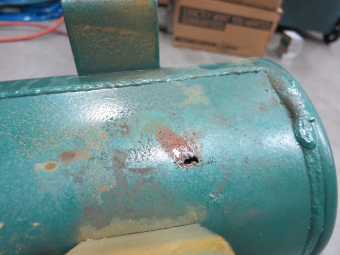
A short while ago we got far enough in the rebuild to test the compressed air subsystem. Not surprisingly, the compressed air tank leaked and could not hold pressure. Upon closer inspection the leak appears to be rust perforation implying the inside is pretty rusty. So we replaced the tank instead of trying to patch it.

10 - Rusted hole

But I was curious: OK, it’s rusty. But how rusty? During a lull in projects (waiting for some parts to arrive) I pulled out the angle grinder, attached the cutting wheel, and merrily started making sparks.

20 - Grinder

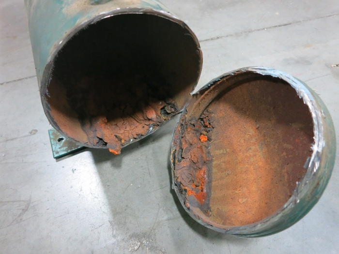
As I made progress cutting, I noticed chunks of degraded metal were falling out of the gap I had cut. Not flakes of rust – chunks of varying color and texture. This is my first hint things are about to get ugly. Once I cut enough to pull away the end of the tank, we can see inside.

30 - Cut open

That’s far more corrosion than I had expected. And while most of the inside surface qualifies as “rusty” the bottom part deserves a stronger word. I can think of a few, but the only one I am willing to put in print is “Yuck”.

40 - Closeup

This sight is something I might expect to see in a home plumbing project fixing the sewer pipe. And this stuff has the soft squishy consistency of… well, the kind buildup you’d find in a sewer drain. This is not something I expected to see inside a piece of industrial equipment.

50 - Full Length

This layer has built up across the entire bottom part of the air tank.

I had originally thought it’d be neat to find the other side of the perforated hole but I was not in the mood to dig through this muck. Even while wearing gloves.

So let this be a lesson to everybody: If you have a compressed air tank, be sure to drain the water out of it regularly, or this might happen to you!

(Cross-posted to Hackaday.io)

Thermoforming Machine Low Amperage Systems Test

We got far enough wiring (and re-wiring) the thermoforming machine to perform an integration test of the low-amperage parts of the machine. This covers almost everything except the heating element.

LowAmpTestSuccess

On the previous test of the compressed air subsystem, we found a leak in the air tank. The leaky tank has since been replaced and this will be a test to see if it works with everything else.

The vacuum subsystem had also been partially tested earlier. For the previous test we only got as far as the vacuum table solenoid. This time we also have the vacuum lines between the solenoid and the vacuum table.

The relay panel had been tested with the following configuration:

  • 24V bench power supply as the input.
  • Manually connecting the control wires in turn like an old style telephone switchboard.
  • Multi-meter reading the output.

This time, the test will put the relay panel in a more realistic configuration:

  • Power will come from the 240V AC to 24V DC power supply on the DIN rail.
  • The control signals will come from the manual operation toggle switch panel.
  • And the most exciting part: the outputs are going to the actual air and vacuum components!

There was much anticipation and trepidation when the power switch was thrown the first time and we see LED indicators on the power supply indicating the system was live. Every switch thrown was a “Will it work?” mystery. The test did its job, exposing a few wiring errors. Fortunately none of them were damaging mistakes and all were trivial to fix.

At the end of the evening, we could control everything except the heating element using the manual operation switch panel: Move all the air cylinders, open and close all the air valves, and activate the electromagnets that hold the frame closed.

We still have lots of things on the to-do list, including some air leaks to track down and fix and plenty of wiring tasks. And there’s still the big intimidating heating element looming in the near future. But all in all, a wonderful morale boosting step on the journey to completion.

(Cross-posted to Hackaday.io)

The Ever-Growing Wiring Job

When we started on this thermoforming machine rebuild project, one of the first things we did was to open the control panel. We looked at the nest of wires back there and tossed the whole tangled mess. Those control wires were a basket case we’re happy to leave behind. But the rest of the machine – the power cables and such – looked OK at first glance.

Unfortunately, they don’t look as good after the second or third glances. Sometimes it’s not a glance at all – it’s seeing (and feeling) them fall apart when we worked in the machine. We expected the wires to be old, and kept our eyes open for signs of aging wires. We just didn’t expect to see them quite so often! This particular example was from the back of the air compressor. When we wanted to clean up the air compressor, we had to disconnect these wires. The act of moving the wires for access and removal broke the age-hardened insulation in many places. So now we have to replace it.

Failing insulation

Every time we get to work on a new area, we find that a new bunch of wires need to be replaced. We’re rapidly approaching the point where it might be easier to rip out every single wire and restart from scratch.

Wiring is tedious work, part of why good electricians make good money. For us, it’s a very real threat against project completion. We’re interested in having our own thermoforming machine, but that interest tends to drop every time we discover 2 new wiring tasks for every one completed. It’s a race to complete before everyone loses interest in the project.

Hopefully the work will be much easier – or at least more rewarding – once the wiring is complete.

Assuming, or course, we get there…

(Cross-posted to Hackaday.io)

Vacuum Table Frame Removal

Around the periphery of the vacuum table on the thermoforming machine, the previous owners built a perimeter using L-brackets. The presence of the frame made sense to help seal in the vacuum. The mystery is the height: The vacuum table and its surrounding frame are the same height as the combined height of the top and bottom parts of the frame holding the workpiece. We had expected the vacuum table to be aligned with the bottom part of the frame, since that’s the height the workpiece will be held at. As this frame is double the height, it would have impacted the workpiece on the way down. We’re left scratching our heads figuring out why this is desirable.

But that mystery isn’t important right now. Since we intend to put this machine to work on low-volume hobbyist projects, we will want to change the size of the workpiece frequently. This would be difficult with the existing system, since changing the size of the workpiece means changing the surrounding frame, greatly increasing the up-front setup work. It might be fine for a commercial production machine but such a barrier on a hobbyist machine would probably mean we’d be too lazy to actually use it.

We’re bouncing around a few ideas that should make it easier to change the size of the work piece in the machine. All of those ideas are incompatible with this existing taller-than-expected frame, so it needs to be removed.

A few jabs with a metal putty knife got things going and the frame popped off shortly afterwards.

Frame Removal

Then the tedious part starts: the putty knives went to work scraping off the sealant that was liberally applied to the bottom of the frame.

Putty Removal

Part of the motivation to invent a new vacuum sealing system is visible here: this surface is quite scratched up and rusty. To make it seal properly with the old system, we need to remove all the paint, sand things flat, and put on a new smooth coat of paint. If we can avoid that work with a clever new sealing system, we’d be happy.

(Cross-posted to Hackaday.io)

Haas Automation is Surprisingly DIY-Friendly.

HaasLogoI hadn’t paid much attention to Haas Automation until recently. When I took my machining classes, there were no Haas machines in the school shop. My awareness of the company did not extend very far beyond the fact a Haas machine is on the cover of my textbook.

That changed recently because Tux-Lab is a fan of Haas Automation. The machine tools (which I aspire to operate) are all Haas machines. I started learning about them and the more I learned, the more I liked what I saw.

First, they are the Home Team. Based in Oxnard, CA, roughly two hours drive away from where I currently live. It is challenging to operate a manufacturing business in the USA, never mind Southern California, and I’m happy to see they’ve found some measure of success in the face of overseas competition.

Second, they have transparent pricing of their equipment listed on a web configuration tool. No “contact your sales representative for a quote” runaround. I’m sure large customers can (and do) negotiate a discount, but at least there’s a price up there on the screen to let people know what they should expect.

The third and most important thing that impressed me: they are friendly to customers who wish to work on their own machines. Sure, they have the standard disclaimer “[work] should be done by authorized trained personnel” but they publish a lot of useful reference information for those who wish to forge ahead anyway. Most other machine tool companies do not publish this information. These non-DIY-friendly companies tell their customers to “contact your authorized service representative.”

And lastly – Haas open their doors to customers (and potential customers) during HaasTec, their own open-house event. See the factory in action, see Haas machines building more Haas machines. That sounds like a Disneyland trip for machining geeks, sign me up!

Motivation to Review My Machining Textbook

Many years ago I developed an interest in machining so I could tackle projects that demand capability beyond pliers and a Dremel tool. I found evening classes offered by Lake Washington Institute of Technology (formerly Lake Washington Technical College). The campus is only a short drive from where I lived at the time. I enrolled in the Machining Technology program on the theory I could learn by attending classes on my way home after work.

In reality I only managed two quarters of classes before my full-time job demands picked up so much I could no longer keep up the night classes. Since I’m unlikely to stock my own home workshop with industrial-level machine tools, I wrote the whole thing off as a self-enrichment learning exercise with no practical application. Or I almost did, because I kept my textbooks on the chance I would need them again.

That was a good thing, because another opportunity has now presented itself. There are a few machine tools at Tux Lab which gives me motivation. If I can get myself up to speed again and prove I’m not likely to break the machines, I might be able to return to those ideas that needed more than a Dremel tool. (And in the years since, I would add “… or a 3D printer.”)

So I dusted off my many-years-old textbook and started reviewing the fundamentals because I believed the fundamentals of machining has not changed. Computer software has evolved tremendously in this time but metal is metal. Still, I was curious about the current status of the book so I looked it up on Amazon.com. My textbook is Machining and CNC Technology (First Edition) by Michael Fitzpatrick (*). As an old textbook, it is going for far less than what I had paid.

According to Amazon, a second edition and third edition has come and gone and we’re now on the fourth edition (*). And because it is the latest and specified by college instructors, the price is over $200. Ouch!

Even in the age of Amazon, the college textbook market is still very distorted.


(*) Disclosure: As an Amazon Associate I earn from qualifying purchases.

Vacuum Subsystem Test

Since we just tested the air subsystem and found problems that will probably require buying parts from McMaster-Carr, we decided to perform a vacuum subsystem test with what we already have on hand to see if we need to add anything else to the shopping list. Only some of the fittings and vacuum lines have been replaced, and the vacuum table itself is in pieces, but we can put together enough to test the vacuum pump, the accumulator tank, the solenoid-actuated vacuum valve, and the fittings and lines connecting them.

We were happy to see the system could generate vacuum beyond an indicated 25 inches of mercury. This measurement is taken with a grain of salt coming from the old vacuum gauge that was on the machine. But while the absolute value (“25 inches”) might be suspect, the relative value is still useful information. We shut off the vacuum pump and went to work on other things. After 15 minutes, the vacuum held steady enough that there was no visible movement of the needle.

Vacuum Holding

The next test is the rate at which vacuum is generated. We don’t need it to be super fast, but we don’t want it to be the limiting factor in cycle time. As soon as the softened workpiece is pulled against the mold, the vacuum should start building back up. It can continue doing so as the completed workpiece is removed and the next workpiece is loaded and heated. By the time the next piece is heated, we want to have sufficient vacuum in the system ready to go instead of having to wait.

Using the solenoid, we opened the valve and admit air into the system, dropping the vacuum down to an indicated 5″ Hg. We closed the valve and started writing down the vacuum reading relative to a stopwatch.

Vacuum Recovery

The recovery rate is acceptable. After one minute it was back up to an indicated 23″ and 90 seconds brings us to 25″. It didn’t have much grunt beyond that – it took double the time (an additional 90 seconds or 3 minutes total) to reach 26.5″, where the needle stopped moving.

We expect a new pump to recover vacuum more quickly, and provide a stronger vacuum, than this tired old thing. But this performance indicates the vacuum pump will not be the limiting factor in our cycle time and that’s good enough.

(Cross-posted to the Hackaday.io project page.)

New Compressed Air Fittings and Lines

We’ve just completed the milestone of replacing the compressed air fittings and lines in the thermoforming machine being rebuilt at Tux-Lab. We replaced the fittings because we expect the old air seals within them to have decayed with age. Since we have everything disassembled, replacing them now is relatively easy and reduces many potential points of failure.

New Air Fitting

The same logic also applied to replacing lines carrying compressed air throughout the machine. For extra bonus, the new air lines are blue and the old ones are green, making it instantly visible which pieces have been replaced.

New Air Line

Once the compressed air subsystem was buttoned up, we wanted to do a subsystem test. Since we have yet to wire up the 220V power distribution, we can’t run the built-in air compressor just yet. So we unplugged the output port of the air compressor and plugged that into the shop air.

Loud hissing announced the presence of a leak in the system. We felt all around the newly installed air lines and fittings, but the source of the leak wasn’t any of the new stuff. We eventually located the source of the leak to the compressed air tank that we had not yet touched. Before this test, the quality of the air tank was a question mark. Now that we have finally pulled it out and gave it a good look, we have answer to that question!

Holey Tank

During disassembly we noted there was no air dryer between the compressor and the tank, so moisture would have collected in this tank. There is a fluid drain port (not visible in this picture) but it doesn’t look like it has ever been used. This hole implies the inside of the tank is a rusty mess and a hole patch repair would only be a futile short-term solution. If we want a self-contained machine not dependent on shop air we will need to replace this tank.

After this discovery, we disconnected the air line from the output port of this tank and hooked that up to shop air. It allowed us to test the rest of the machine.

  • The mechanism to move the heater rearward seems OK.
  • The mechanism to move the heater forward has a leak that needs to be investigated.
  • Trying to move the heater forward/back repeatedly showed no problems (aside from the above leak.)
  • The mechanism to move the frame up/down each seems OK individually.
  • Trying to actuate up/down movement rapidly would cause the two sides of the air cylinder to fight each other. We are missing an air relief mechanism somewhere in the system. Either we forgot we removed something during disassembly, or an existing relief mechanism has plugged up.

(Cross-posted to the Hackaday.io project page.)

New Project: Thermoforming Machine Touchscreen Control

I help where I can in the Tux-Lab effort to rebuild the old thermoforming machine. I’ve been doing more learning than helping, though, since others have more experience with industrial machinery than I do. The initial goal is to get things up and running under manual control, and we’ll tackle automation later.

That doesn’t keep us from chatting about ideas for the automation effort, which is roughly divided up into three tiers of complexity.

At the low-end, we can drive it with a PIC micro controller. A modern PIC should be more than capable of duplicating the level of automation that existed in a decades-old machine. It would be the lowest-cost solution, if the cost difference was significant enough to matter.

The mid-tier option is an Arduino. It should be the easiest to get up and running due to the components already integrated on an Arduino board and the large existing library of code we can draw upon.

Both of the above would offer the option of reusing the control panel as-is, which would be important if we wanted to preserve the exterior appearance of the machine. At the moment it is not a goal to do so – we are not a museum and see little value in historical preservation on this machine. Especially since it’s a huge mess of wires in there.

IMG_5242

So, as can be expected of a bunch of tinkerer types, the dreams started getting wilder and wilder. It wasn’t long before we started talking about a touchscreen-controlled thermoforming machine that is network-connected for job monitoring and logging. Which leads us to the high-tier option: a Raspberry Pi with the matching LCD touchscreen.

The team has members with experience in PIC programming, and in Arduino programming, but we’re light on Raspberry Pi programming expertise. Since this is something I wanted to learn to do anyway, I volunteered to investigate.

In the short term we’re still focused on the manual toggle switch operation mode. In the medium term we might still implement Arduino control. And that might be a good enough place to stop, but I wanted to see if we can turn the wild dream into reality.

Tux-Lab Thermoforming Machine Disassembly

One of the projects on the Tux-Lab to-do list is to revive a thermoforming machine. Purchased cheaply in non-working condition, it has potential to enable some very interesting projects. It has been gathering dust while waiting for enough interest from enough people to reach critical mass to start the project. I think we finally reached that point! We pulled it out of the corner it’s been sitting in, and merrily started pulling everything apart.

Disassembled

I thought we would document the original condition as we pulled things apart, but it quickly became apparent there’s no “original condition” to document. The wide range of age and quality of components made it clear it has seen continual modifications in its decades of service. The decision was made to go all the way back to fundamentals.

The bottom cabinet held the air machinery: a vacuum pump and an air compressor, each with an associated accumulator tank. They had all been bypassed with external connectors, which was not a vote of confidence in their functionality. We were hopeful that the previous owner(s) just wanted to reduce noise and vibration by hooking into their shop’s existing compressed air and vacuum lines.

The vacuum pump turned and could pull 26 inches of mercury, which is quite acceptable. The air compressor pushed out 40 psi, which was rather was less so. Fortunately a disassembly and cleanup was enough to help it push 100 psi. The two air tanks are question marks.

There are two air cylinders in this machine: One moves the thermoforming frame up and down, the other  moves the heater front and back. A quick test of both revealed they move and no air leak hissing was audible at either of their end positions.

The thermoforming frame was designed with two electromagnets to hold it closed. We assumed the magnets were broken because somebody installed some Home Depot quality mechanical latches. But we were able to energize the coils and feel it hold. Maybe the failure was in the control circuitry, maybe it doesn’t hold strongly enough for some task. We’ll find out for sure later.

Latch

The brains of the machine are the clearest indication of the age. We see a lot of discrete logic components and no indication of a microcontroller at the heart of it all. The control panel has a button “Automatic” and we wonder what that used to do. For the moment we will not worry about it: the initial milestone is to get it up and running in manual operation mode. If we get around to implementing an automatic cycle, we’ll pull in an Arduino or something modern to orchestrate the various bits and pieces.

Brains

On the assumption that old air hoses and fittings will be leaky, they will be replaced with new parts. The air valves should still be good and will be used until proven otherwise. Same for the big honkin’ contactors (240V, 40A) in the back to control the heater.

Orders have been placed for replacement parts – once they show up we can install them to get a better idea of how everything will (or won’t) work together.

(This project is cross-posted to Hackaday.io)

Si7021 Sensor to Raspberry Pi to PIC to LED

I started this I²C project by creating a simple I²C-controlled LED display using a PIC micro controller. Then I found an I²C Python Raspberry Pi library to communicate with my PIC. The next addition to the mix should be an I²C device I did not create, to verify my code plays well with others.

While talking about I²C at Tux-Lab, one of the past projects came up: a breakout board for the Si7021 temperature and humidity sensor. A unit was brought out for show during this conversation. This particular unit was built a few years ago and has yet to be incorporated into a project.

A web search confirmed this is quite a popular sensor. Lots of sample code and projects. Both Adafruit and Sparkfun sell breakout boards similar to the one Tux-Lab created. And the sensor is also part of the popular Sense HAT. I looked at the data sheet and thought it looked like a good place to start. Best of all, a search for existing code found one in the “Examples” section of the Pi GPIO library I wanted to learn anyway.

I asked to borrow that unused breakout board and added it to my bread board. (Visible in the lower-left of the attached picture.) The additional wiring was trivial, most of the work was on the software side learning Python basics. It didn’t take terribly long to create a rudimentary thermometer. My Python code running on the Pi uses I²C to query the Si7021 for temperature, converted that data for display, and sent that data out the same I²C bus to the PIC.

With the work and learning I’ve put in, I now have an overly complicated contraption that tells me my work space temperature is 75.18 degrees Fahrenheit.

TemperatureLED
No decimal point on the LED because I ran out of pins on the 18-pin PIC16F1847 chip.


FreeNAS Box v2: Construction Complete

After spending an afternoon + evening at a Tux-Lab work session, I have my FreeNAS Box v2! It’s always fun to see my idea turned into reality.

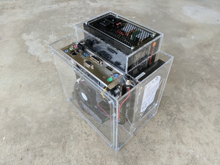
FreeNASv2 Complete

The first thing I appreciated was the fact that the components are clearly visible through the acrylic panels. And even better, the messy tangle of wires are hidden behind them. This reversal from v1 is the best aesthetic change.

The other major design requirement – that both cooling fans be visibly spinning – is also present but it doesn’t have as much of an immediate aesthetic effect.

After I’ve kept it on and running overnight, I checked the temperature around the box the following morning. I think it would be neat to check thermal performance with a FLIR thermal imaging camera but lacking such toys I went with the low-tech way of putting my hands at various places around the box to feel the temperature.

The front chamber – where the CPU and motherboard reside – has a slight temperature gradient from top to bottom but overall it was relatively cool to the touch. This was expected as the CPU basically sat idle all night. It also means I won’t need to cut a hole in the front door for a direct air intake.

The rear chamber, with the power supply and both hard drives, is where most of the heat is generated. The two drives were warm to the touch signifying that they’ve been spinning all night and getting some amount of cooling to keep them from getting hot.

The power supply fan was running and the power supply case was cool to the touch. The power meter read 30W for the FreeNAS box in this steady-state idle state. This is a very light load for a 600W-rated power supply, reflected in its cool running temperature.

Vacuum Table – Spoilboard and Gasket

Now that we have a baseline on the vacuum table performance, time to start performing modifications to see what happens.

The easiest thing to reduce air resistance is to remove layers – we don’t strictly need the spoilboard in this setup, so it is removed. We then added some rubber gaskets to improve the seal between the plenum and the fixture, which should reduce air leaking past that particular junction.

8 Plenum Gasket Fixture small
Spoil board removed, gasket added – 25 inches

These modifications did not drop the vacuum of an empty fixture – in fact vacuum was boosted by 2 inches to 25. This implied having the spoilboard in the setup was letting a lot of air slip around the fixture. Removing it was a good call.

9 Plenum Gasket Fixture Blanks small
Adding work pieces increased to 26 inches.

When the work pieces are in place, the vacuum went up another inch to 26 inches. Less air is leaking past the work pieces, and they are now held by about one inch of mercury (roughly half a pound per square inch.)

We haven’t put any effort into improving the sealing between the work pieces and the fixture. How much gain can we realistically expect from the effort? In order to get a rough estimate of how much more we might gain, we draped a plastic sheet over the fixture.

10 Plenum Gasket Fixture Sheet small
Replacing work pieces with a plastic sheet boosted to 27.5 inches.

Looks like we have about 1.5 inches of mercury we can gain from better workpiece-to-fixture sealing.

This is a promising start, as this tells us we’re in reach of a decently high level of vacuum for work-holding. We now need to put some effort into the other side – improve the path for the vacuum to reach the work pieces and hold them in place.

More improvements to come!

Vacuum Table – Baseline Measurements

The CNC router at Tux-Lab has been under-utilized partly due to its under-performing vacuum table. It has a poor track record on an existing project, and we want to understand why (and hopefully fix the problem) before doing more projects on the CNC router.

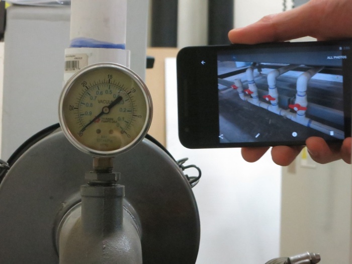
To narrow down the cause, we will record the pump’s vacuum gauge reading at various configurations. We use a phone to take a picture identifying the vacuum configuration. We then hold that picture up next to the gauge and take a picture of the phone and the gauge together.

Establish the bounds

First, we get the upper bound: once the pump is up and running, close all the zone valves. The reading – nearly 30 inches of mercury – confirms the pump itself and the majority of the vacuum piping is in good working order.

2 Zone Valves small
Maximum vacuum – nearly 30 inches, good!

The lower bound is obtained by opening all zone valves and place nothing on the spoilboard. When in working configuration, the vacuum will never be weaker than this 7.5 inch reading.

6 Spoilboard small
Minimum vacuum – roughly 7.5 inches.

Most of the tests confirmed that the vacuum setup itself appears to be in good working order. We only started seeing problematic numbers once we started involving the spoilboard and the project fixture. Good news since these are the easiest pieces to fix.

4 Spoilboard Fixture small
Fixture without work pieces – just under 23 inches.

Past runs of the existing project has been done with the fixture mounted on the spoilboard. The vacuum reading of this configuration is surprisingly high at a hair under 23 inches. Indicating a lot of air resistance despite being carved from low density fiberboard.

We then added the work piece blanks on top of the fixture and measured again.

5 Spoilboard Fixture Blanks small
Fixture with work pieces – just over 23 inches.

The vacuum barely changed, to just a hair over 23 inches. This is a problem: it tells us the air can easily find a path around the work pieces so very little of atmospheric pressure is applied to hold pieces in place.

Now the objective is to modify the setup to (1) reduce the vacuum reading of an empty fixture and also (2) increase the vacuum reading of the populated fixture.

Increasing difference between these two readings should increase the holding power.

Mini-ITX Server Box

Mini-ITX Server CADTux-Lab had components on hand for a completely fan-less bare-bones Mini-ITX system. A small board with a passively-cooled CPU, a small 12V DC to ATX DC power supply that didn’t need a fan, and a solid state drive for storage. All it needed was a simple basic box to keep everything in – which made it an ideal learning project as a follow-on to FreeNAS box V1. (Well, it can be argued that this simple box should have come first… but that wasn’t the order things ended up being.)

This time there was no design challenge with hard drive placement or power supply fan clearance. Just a simple box with two sets of holes so convection will pull cold air from the bottom and let hot air out the top. The back plate had opening for the standard ITX motherboard port plate, plus two holes: One for the 12V DC power input, and the other for a momentary-on power switch.Mini-ITX Server

The result was an upgrade from its previous placement, which was the bare circuit board sitting on top of a cardboard box. Now it has some minimal protection against accidents like an errant dropped paperclip shorting things out.

This machine is now set up with the Xen hypervisor and ready to run the server-side code of whatever future projects arise at Tux-Lab, as long as that code can run in a Xen virtual machine.

FreeNAS Box V1 Prototype

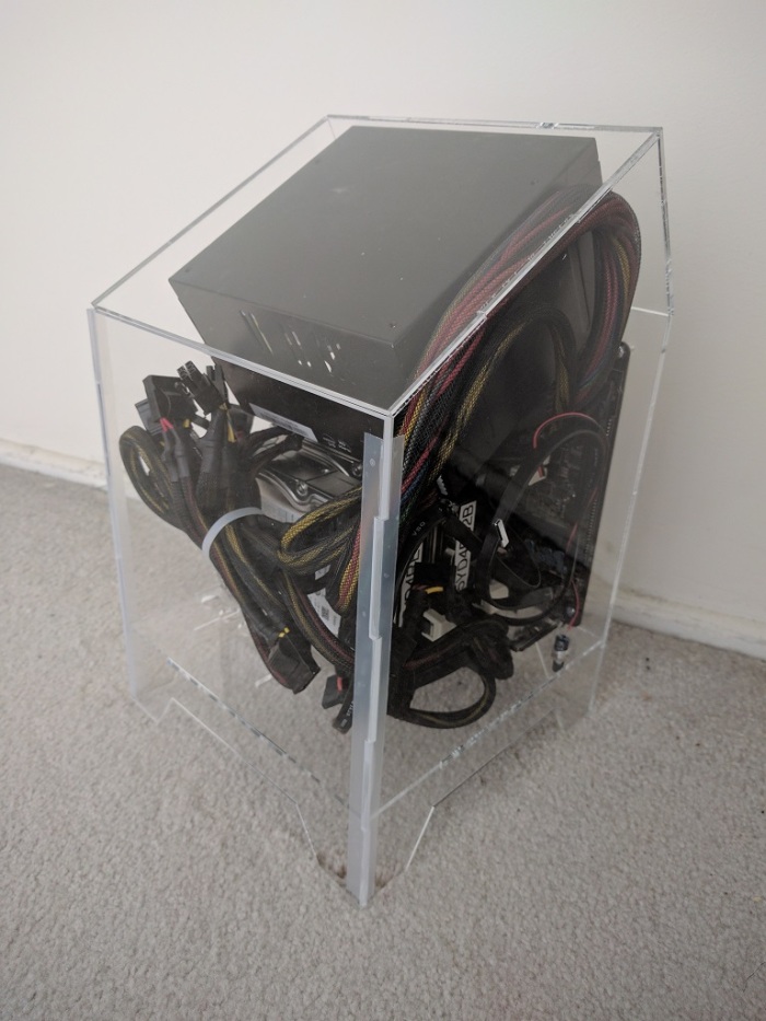
FreeNASv1With the concept designed, it’s time to head over to Tux-Lab to build it!

To be honest, it was not fully designed for use as a computer case. Since this was my first effort designing for acrylic construction I expected to run into some amateur mistakes very quickly. As a result I had left some known design issues open to be resolved in future prototypes. One example: I had not designed any kind of door or hinge. The prototype panels are mostly glued together, except for the front panel which is held in place by tape.

Aesthetically, I am pleased with how the clear acrylic looked though I am not pleased at how much of a rat’s nest the power supply cables became. Taming wires is a perpetual challenge. I now understand why Apple enclosed all the ugly guts of the G4 cube in shiny aluminum shell inside the clear acrylic shell.

Other than the messy computer wires, the clear acrylic does hint at the illusion of a computer floating in mid air. I’m pretty happy with that, but it’s not enough to offset the tangle of wires. Next prototype will either have good cable management (takes effort) or have some dark colored acrylic to hide the interior (much easier.)

The cooling functionality worked as designed: the intake air is drawn from the bottom, past the two hard drives keeping them cool, and out the top.

Similarly, the designed goals of tilted-PSU (power supply unit) space optimization was successful, as did the gentler turn demanded of the wires. However, there was an unforeseen deal-breaker of an issue.

Uh-oh!

FreeNASv1_FlawOn the back side of the tilted-PSU, we see that the tilt has pressed the bottom of the PSU up against the wire bundle at the top of the motherboard. The tight quarters mean individual wires of the bundle tried to relieve the crowding by moving into the space for the PSU fan preventing it from turning. Since the PSU fan is the primary air-mover for this enclosure, a stopped fan is obviously not acceptable.

Other notes

Space utilization efficiency has room for improvement. Some of this was caused by the desire to emulate the Apple G4 cube and have a square footprint. (20 cm squared!) The squareness was completely unnecessary and future iteration will likely have a rectangular footprint for space efficiency.

There was uncertainty about how well 3mm acrylic can hold the weight of the power supply unit. It proved to be surprisingly capable once the two top sheets reinforced each other at right angle.

Amateur Hour: A laser cutter only cuts vertically. There was no way to cut a 30 or 60 degree edge for the tilted PSU section! For this learning exercise, the cornered edges are simply left open and unattached.

The angled PSU was a novel idea to solve specific problems, but it caused new ones and also unsuitable for laser cut acrylic construction. That was a fun experiment, but we’ll have to leave the angled PSU concept behind for the next prototype.

Luggable Frame Experiment #2

Catleap2The second iteration of the luggable frame experiment addressed the failings of the first version by relying less on acrylic and more on aluminum. The first iteration was a good experiment to see if acrylic was strong enough for the work. Once V1 conclusively proved the weaknesses, it’s time to fall back to the known quantity.

The following changes were made for version 2:

Extrusion upgrade: In the interest of greater rigidity, the extrusions themselves were upgraded from Misumi HFS3 (15mm x 15mm cross section) to HFS5 (20mm x 20mm). The smaller extrusions seemed to be doing the job but they did exhibit some flex. And we had HFS5 conveniently on hand so let’s use it!

Connection upgrade: In V1 the extrusion T-joint at the base of the frame was held together by the side pieces of acrylic. Though it seemed to work, V2 went with a stronger solution by using metal connectors for the joint. (Misumi HBLFSNF5).

Handle upgrade: The V1 handles were part of the acrylic assembly. With the reduction in acrylic usage, there wasn’t enough left to carry the load of the whole frame. So the handle became another aluminum extrusion.

Catleap2-RearPC tray upgrade: This was the first acrylic thing that failed in V1. The PC is now held in place by aluminum structure instead of an acrylic cutout which makes it quite secure. Three of the extrusion right-angle connectors were re-purposed as “claws” to keep the PC case in place.

Catleap2-SideVESA mount upgrade: The worrisome flex in the Catleap monitor enclosure was traced down to the metal threads inside the Catleap enclosure that were longer than the thickness of the enclosure plastic. This meant when the mounting screws fully engaged, there was still a bit of space between the VESA mount plate and the monitor’s rear surface, allowing movement. A spacer plate was added to fill that gap. Now the VESA mounting plate on the frame is fully pressed against the monitor’s rear surface, greatly reducing the flex.

All this additional structure added up to a very secure frame for carrying around the Yamakasi Catleap monitor with the HP Z220 computer. Unfortunately it also added weight which was a concern even before the frame came into the picture. The heft means this is probably the end of the line for the Catleap + Z220 experiments. Frame V2 will serve as a perfectly good workstation albeit not a very portable one.

The idea of building a Luggable PC around a commercially available monitor will continue, with the focus shifting to using smaller and lighter components.

Luggable Frame Experiment #1

Catleap1The dimensions for my Luggable PC project were determined by the components within. The width and height, specifically, were dictated by the LCD screen module. Even though I made the CAD files public for anybody to build their own Luggable PC, in practical terms only people with the exact same LCD module would be able to use the files without modification.

A friend who saw the Luggable PC was interested in generalizing the concept and create a frame for lugging a (not disassembled) screen alongside its (also not disassembled) PC. Relative to my project, it would be easier to build and less specialized to the components within, with a trade-off in larger size and heavier weight.

I thought it was a great idea to explore and joined in the experiment. We each came up with a design, and we built both of them at Tux-Lab to see how the ideas translated into reality.

This blog post is a brief summary of my first experiment.

The Components

The monitor is an Yamakasi Catleap monitor, built around a 27″ IPS panel with 2560×1440 resolution. The specific dimensions don’t really matter, as it will be mounted via the standard 75mm VESA pattern on the back. Any large monitor with 75mm VESA pattern would fit as-is, and only minor modifications would be necessary to accommodate monitors with a different mounting pattern.

The PC is a HP Z220, small form factor PC from the HP business line available with a range of components to trade off processing power against price. For the purposes of this experiment, the important details are its height of 331mm and depth of 100mm. Thought not a standardized dimension, many small form factor PCs are roughly the same size.

The Construction

The core of the frame are built from 15mm aluminum extrusions (Misumi HFS3) for strength and the remainder of the frame are made from 6mm laser-cut acrylic fastened to the extrusions via M3 nuts and bolts.

Making the panels from laser-cut acrylic has the advantage of simpler modifications. Many of the critical dimensions in my Luggable PC 3D CAD file has the problem that, when changed, they trigger cascading changes that need to be reconciled. When designing for the 2D tool path of laser laser cutting, it is easier to keep modifications in mind so that a change in one sheet does not cascade to other sheets.

Example #1: The frame has a 331mm x 100mm hole to fit the Z200 case. This can be adjusted to fit any other SFF frame without cascading changes to other components.

Example #2: The monitor mount pattern can be changed, and the mount position can be moved up or down to adjust elevation of the monitor.

The Result

CompleteI had never designed for laser cutting before and was happy for the chance to do something on the Tux-Lab laser cutter. I knew that, having little experience with the material, my first few designs will have some amateurish flaws. So this frame #1 was fairly minimalist just to see what happens.

I didn’t have a good grasp how many fasteners I would need to hold everything together. I laser-cut roughly double the number of fastener positions than what I think I would need, as it is easier to have more options rather than less. For the assembly I only installed fasteners in every other hole.

The screen mount was surprisingly successful. We questioned whether 6mm acrylic would be suitable for holding up the Catleap monitor by its 75mm VESA mounts. When we found some worrisome flex, the suspicion went immediately to the 6mm acrylic but it turned out the Catleap monitor enclosure was the source of the flex.

When attempting to install the PC, we found that the case itself would fit just fine but the rubber feet attached to the side of the case did not. I added cutouts in the CAD file but it seemed wasteful to cut entirely new pieces of acrylic just for the little feet cutouts. For purposes of experimentation, a Dremel tool was used to cut gaps to clear the rubber feet.

After the frame was assembled with the screen and the PC, we started plugging in all the cables and wires and I realized I had forgotten to account for the cables. There’s no good place to coil up the excess so they kind of dangle and stand ready to catch on something inconvenient.

The entire assembly was built in a tiny fraction of the time of my Luggable PC and included a much larger monitor with a much higher resolution. The trade off was almost doubling of the weight. The handle, part of the acrylic assembly, appeared to be sufficient to manage the weight.

I carried it across Tux-Lab and quickly encountered the first failure.

The Failure

Lesson of the Day: Sharp internal corners are bad.

My amateur mistake was cutting a sharply cornered rectangle to hold the PC. The sharp corners concentrated the physical load of the PC into a small point in the 6mm acrylic, which protested the poor design by breaking apart.

The next experiment will incorporate this lesson.

Build, fail, learn, iterate, repeat.

Broken