Google AIY Vision Kit

A few years ago, I tried out the Google AIY “Voice” and “Vision” kits. They featured very novel hardware but that alone was not enough. Speaking as someone not already well-versed in AI software of the time, there was not enough documentation support to get people like me onboard to do interesting things with that novel hardware. People like me could load the default demo programs, we could make minor modifications to it, but using that hardware for something new required climbing a steep learning curve.

At one point I mounted the box to my Sawppy rover’s instrument mast, indicating my aspirations to use it for rover vision, but I never got much of anywhere.

The software stack also left something to be desired, as it built on top of Raspberry Pi OS but was fragile and easily broken by Raspberry Pi updates. Reviewing my notes, I realized I published my notes on AIY Voice but the information on AIY Vision was still sitting in my “Drafts” section. Oops! Here it is for posterity before I move on.

Google AIY Vision Kit

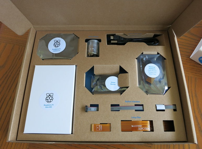
The product packaging is wonderful. This was from the era of Google building retail products from easily recycled cardboard. All parts were laid out and neatly labeled in a cardboard box.

Google AIY online instructions.jpg

There was no instruction booklet in the box, just a pointer to assembly instructions online. While fairly easy to follow, note that instructions were written for people who already know how to handle bare electronic circuit boards. Handle the circuit boards by the edges and avoid touching components (especially electrical contacts) and such. Complete beginners unaware of basics might ruin their AIY kit.

Google AIY Vision Kit major components

From a hardware architecture perspective, the key is the AIY Vision bonnet that sat on top of a Raspberry Pi Zero WH. (W = WiFi, H = with presoldered header pins.) In addition to connection with all Pi Zero GPIO pins, it also connects to the Pi camera connector for direct access to camera feed. (Normal data path: Camera –> Pi Zero. AIY Vision data path: Camera –> Vision Bonnet –> Pi.) In addition to the camera, there is a piezo buzzer for auditory feedback, a standalone green LED to indicate camera is live (“Privacy LED”), and a big arcade-style button with embedded LEDs.

Once assembled, we could install and run several visual processing models posted online. If we want to go beyond that, there are instructions on how to compile trained TensorFlow models for hardware accelerated inference by the AIY Vision Bonnet. And if those words don’t mean anything (it didn’t to me when I played with the AIY Vision) then we’re up a creek. That was bad back then, and now that a few years have gone by, things have gotten worse.

  1. The official Google AIY system images for Raspberry Pi hasn’t been updated since April 2021. And we can’t just take it and pick up more recent updates, because that breaks bonnet functionality.
  2. The vision bonnet model compiler is only tested to work on Ubuntu 14.04, whose maintenance updates ended in 2019.
  3. Example Python code is in Python 2, whose support ended January 1st, 2020.
  4. Example TensorFlow information are for the now-obsolete TensorFlow 1. TensorFlow 2 was a huge breaking change, and it takes a lot of work — not to mention expertise — to migrate from TF1.x to TF2.

All of these factors together tell me the Google AIY Vision bonnet has been left to the dusty paths of history. My unit has only ever ran the default “Joy Detection” demo, and I expect this AIY Vision Bonnet will never run anything else. Thankfully, the rest of the hardware (Raspberry Pi Zero WH, camera, etc.) should have better prospects of finding another use in the future.

Power Control Board for TrueNAS Replication Raspberry Pi

Encouraged by (mostly) success of controlling my Pixel 3a phone’s charging, the next project is to control power for a Raspberry Pi dedicated to data backup for my TrueNAS CORE storage array. (It is a remote target for replication, in TrueNAS parlance.) There were a few reasons for dedicating a Raspberry PI for the task. The first (and somewhat embarrassing) reason was that I couldn’t figure out how to set up a remote replication target using a non-root account. With full root level access wide open, I wasn’t terribly comfortable using that Pi for anything else. The second reason was that I couldn’t figure out how to have a replication target wake up for the replication process and go to sleep after it was done. So in order to keep this process autonomous, I had to leave the replication target running around the clock, and a dedicated Raspberry Pi consumes far less power than a dedicated PC.

Now I want to take a step towards power autonomy and do the easy part first. I have my TrueNAS replications kick off in response to snapshots taken, and by default that takes place daily at midnight. The first and easiest step was then to turn on my Raspberry Pi a few minutes before midnight so it is booted up and ready to receive replication snapshot shortly after midnight. For the moment, I would still have to shut it down manually sometime after replication completes, but I’ll tackle that challenge later.

From an electrical design perspective, this was no different from the Pixel 3a project. I plan to dedicate another buck converter for this task and connect enable pin (via a cable and a 1k resistor) to another GPIO pin on my existing ESP32. This would have been easy enough to implement with a generic perforated prototype circuit board, but I took it as an opportunity to play with a prototype board tailored for Raspberry Pi projects. Aside from the form factor and pre-wired connections to Raspberry Pi GPIO, these prototype kits also usually come with appropriate pin header and standoff hardware for mounting on a Pi. Looking over the various offers, I chose this particular four-pack of blank boards. (*)

Somewhat surprisingly for cheap electronics supply vendors on Amazon, this board is not a direct copy of an existing Adafruit item. Relative to the Adafruit offering, this design is missing the EEPROM provision which I did not need for my project. Roughly two-thirds of the prototype area has pins connected as they are on a breadboard, and the remaining one-third are individual pins with no connection. In comparison the Adafruit board is breadboard-like throughout.

My concern with this design is in its connection to ground. It connects only a single pin, designated #39 in most Pi GPIO diagrams and lower-left in my picture. The many remaining GND pins: 6,9,14,20,25,30, and 34 appear to be unconnected. I’m not sure if I should be worried about this for digital signal integrity or other reasons, but at least it seems to work well enough for today’s simple power supply project. If I encounter problems down the line, I can always solder more grounding wires to see if that’s the cause.

I added a buck converter and a pair of 220uF capacitors: one across input and one across output. Then a JST-XH board-to-wire connector to link back to my ESP32 control board. I needed three wires: +Vin, GND and enable. But I used a four-pin connector just in case I want to surface +5Vout in the future. (Plus, I had more four-pin connectors remaining in my JST-XH assortment pack than three-pin connectors. *)

I thought about mounting the buck converter and capacitors on the underside of this board. There’s enough physical space between the board and the Raspberry Pi to fit them. I decided against it on concern of heat dissipation, and I was glad I did. After this board was installed on top of the Pi, the CPU temperature during replication rose from 65C to 75C presumably due to reduced airflow. If I had mounted components underneath, that probably would have been even worse. Perhaps even high enough to trigger throttling.

I plan to have my ESP32 control board run around the clock, so this particular node doesn’t have the GPIO deep sleep state problem of my earlier project with ESP8266. However, I am still concerned about making sure power stays on, and the potential problems of ensuring so.


(*) Disclosure: As an Amazon Associate I earn from qualifying purchases.

Micro Sawppy Beta 1 Electronics

The past several posts have described various aspects of Micro Sawppy Beta 1 (MSB1) that are explorations of new ideas for a little rover. Since there were already many new ideas piled onto the little guy, I decided the control electronics and software should step back and reuse known quantities. Even though I don’t intend this to be the final approach, I wanted to reuse existing components here just to keep things from going too wild and confused if the little rover should encounter problems.

Hence the onboard electronics of MSB1 is very close to those used on Sawppy, which was in turn adapted from code written for SGVHAK Rover. Not from the official JPL Open Source Rover instructions, but the hack I hastily slammed together for its world premier at Southern California Linux Expo. Back then we faced the problem of a broken steering gearbox a week ahead of the event, and it would take over a week for replacements to arrive. So while Emily hacked up a way for a full-sized RC servo to handle steering, I hacked up the rover software to add option to control a servo via what I had on hand: the Adafruit PWM/Servo HAT.

Years later, I still have that same HAT on hand and now I have a rover full of micro servos. Putting them together was an obvious thing to try. My software for that servo steering hack turned out to be very easy to adapt for continuous rotation servos powering the wheels. (Only a single bug had to be fixed.)

There was another happy accident: since the SGVHAK rover software already had software provisions for steering trim, it was easy to use that for throttle trim as well. This was useful to compensate for the fact that the converted continuous rotation servos in the six wheels aren’t necessarily centered like they theoretically were. Resistors with identical markings don’t actually offer perfectly equal resistance, and the control circuit of a cheap micro servo isn’t very good about precise voltage measurements anyway. If I didn’t have this software throttle trim control, it might have been much more difficult to get MSB1 up and running.

For power supply I had a small 2-cell Lithium Polymer battery on hand, previously seen on these pages in exploration of a thrift store Neato. Dropping its voltage (8.4V when fully charged) down to something that wouldn’t fry the micro servos was the job of MP1584 buck converters. I had discovered these worked well for powering a Raspberry Pi and one of them is again enlisted into that role. In order to reduce the chances of a power sag causing the Raspberry Pi to reset, I added a second buck converter to give the micro servos an independent power plane. Both buck converters are soldered onto the little prototyping area Adafruit provided on their HAT. Once I had the electronics circuit stack assembled, I could start wiring up all the components.

Raspberry Pi GPIO on Node-RED Needs Raspberry Pi OS

I didn’t manage to get Bluetooth Low Energy (BLE) running in Node-RED on a Windows PC, so experimentation moved on to other hardware platforms. Specifically the hardware hacking darling Raspberry Pi. I knew it was possible because of the number of projects that already existed, plus Node-RED has an instruction page dedicated to Raspberry Pi installation. This would be straightforward… except I intentionally made things difficult for myself.

The twist is that my Raspberry Pi 3 readily available for experimentation was most recently set up to check out ROS on arm64. Which meant it was running Ubuntu 20 for 64-bit Raspberry Pi instead of the default Raspberry Pi OS. (Formerly known as Raspbian.) I was confident all the fundamental parts of Node-RED such as flows and network I/O would continue functioning, which makes it a low-power alternative to running Node-RED on a PC. But the other reason to run Node-RED is to interface with devices via Raspberry Pi’s GPIO pins. I wanted to know how well that would work under arm64 Ubuntu.

And I got my answer: it does not work. It appears whatever means Node-RED employed to access Raspberry Pi GPIO is not available on Ubuntu arm64 builds. I assume it is possible to install and/or port over the components required for such support, but today’s experiment is just to see if it works out of the box and now I know it does not.

31 Aug 20:36:53 - [info] Node-RED version: v1.1.3
31 Aug 20:36:53 - [info] Node.js version: v12.18.3
31 Aug 20:36:53 - [info] Linux 5.4.0-1016-raspi arm64 LE
31 Aug 20:36:54 - [info] Loading palette nodes
/bin/sh: 1: /home/ubuntu/.node-red/node_modules/node-red-node-pi-gpio/testgpio.py: not found
31 Aug 20:36:56 - [warn] rpi-gpio : Raspberry Pi specific node set inactive

Update on ARM64: ROS2 on Pi

When I last looked at running ROS on a Raspberry Pi robot brain, I noticed Ubuntu now releases images for Raspberry Pi in both 32-bit and 64-bit flavors but I didn’t know of any compelling reason to move to 64-bit. The situation has now changed, especially if considering a move to the future of ROS2.

The update came courtesy of an announcement on ROS Discourse notifying the community that supporting 32-bit ARM builds have become troublesome, and furthermore, telemetry indicated that very few ROS2 robot builders were using 32-bit anyway. Thus the support for that platform is demoted to tier 3 for the current release Foxy Fitzroy.

This was made official on REP 2000 ROS 2 Releases and Target Platforms showing arm32 as a Tier 3 platform. As per that document, tier 3 means:

Tier 3 platforms are those for which community reports indicate that the release is functional. The development team does not run the unit test suite or perform any other tests on platforms in Tier 3. Installation instructions should be available and up-to-date in order for a platform to be listed in this category. Community members may provide assistance with these platforms.

Looking at the history of ROS 2 releases, we can see 64-bit has always been the focus. The first release Ardent Apalone (December 2017) only supported amd64 and arm64. Support for arm32 was only added a year ago for Dashing Diademata (May 2019) and only at tier 2. They kept it at tier 2 for another release Eloquent Elusor (November 2019) but now it is getting dropped to tier 3.

Another contributing factor is the release of Raspberry Pi 4 with 8GB of memory. It exceeded the 4GB limit of 32-bit addressing. This was accompanied by an update to the official Raspberry Pi operating system, renamed from Raspbian to Raspberry Pi OS, is still 32-bit but with mechanisms to allow addressing 8GB of RAM across the operating system even though individual processes are limited to 3GB. The real way forward is to move to a 64-bit operating system, and there’s a beta 64-bit build of Raspberry Pi OS.

Or we can go straight to Ubuntu’s release of 64-bit operating system for Raspberry Pi.

And the final note on ROS2: a bunch of new tutorials have been posted! The barrier for transitioning to ROS2 is continually getting dismantled, one brick at a time. And it’s even getting some new attention in long problematic areas like cross-compilation.

Raspberry Pi Web Kiosk Boots Faster On Raspbian Than Ubuntu Core

My adventures into the lightweight Ubuntu Core operating system was motivated by a 14-year old laptop with Intel CPU. By multiple measures on the specification sheet, it is roughly equivalent to a modern Raspberry Pi. (~1 GHz processor, ~1GB RAM, ~30GB storage, etc.) As a test drive, I had tried setting it up as a web kiosk and failed due to incomplete graphics driver support. (Though I did get it working on a modern laptop.)

Which leads to the next question: how well does Ubuntu Core perform on a Raspberry Pi performing the exact same web kiosk task? And how does that compare to doing the same thing on Raspbian OS? They’re both variants of Linux trimmed down for less powerful hardware. Raspbian is packed with features to help computing beginners get started, and Ubuntu Core has almost no features at all to offer a clean baseline.

My workbench is not a comparison test lab so I didn’t have many copies of identical hardware for a rigorous comparison. Two monitors were close but not quite identical in resolution. (1920×1080 for the LG, 1920×1200 for the Dell.) The two Raspberry Pi should be identical, as should the microSD cards, but they’re not powered by identical power supplies. To establish a baseline, I set them both up for Raspberry Pi web kiosk using my top search hit for “Raspberry Pi Web Kiosk”. Then launched them side-by-side a few times to see how close their performance were from power-up to rendering a web page. (For this test, the Hackaday.com site.) This took approximately 40-45 seconds, sometimes one is faster and sometimes the other is faster. For some runs, the two systems were within one second of each other, sometimes they were almost 5 seconds apart. Establishing the fact this comparison method has a measuring error of several seconds.

With an error margin established, I removed one of their microSD cards and installed Ubuntu Core for Raspberry Pi 3 on it. Once initial configuration were complete, I installed snaps for the web kiosk tutorial I followed earlier for the Dell laptops. I was very curious how fast a stripped-down version of Ubuntu would perform here.

The answer: not very, at least not in the boot-up process. From power-up to displaying the web page, Ubuntu Core web kiosk took almost 80 seconds. Double the time necessary for Raspbian, and that was even with a full install of Raspbian Buster with zero optimizations. There are many tutorials online for building a Raspbian-based web kiosk with stripped-down list of components, or even starting with the slimmer Raspbian Buster Lite operating system which would only get faster.

There may be many good reasons to use Ubuntu Core on a Raspberry Pi (smaller attack surface, designed with security in mind, etc.) but this little comparison indicates boot-up speed is not one of them.

Raspberry Pi GPIO Library Gracefully Degrades When Not On Pi

Our custom drive board for our vacuum fluorescent display (VFD) is built around a PIC which accepts commands via I2C. We tested this setup using a Raspberry Pi and we plan to continue doing so in the Death Clock project. An easy way to perform I2C communication on Raspberry Pi is the pigpio library which was what our test programs have used so far.

While Emily continues working on hardware work items, I wanted to get started on Death Clock software. But it does mean I’d have to work on software in absence of the actual hardware. This isn’t a big problem, because the pigpio library degrades gracefully when not running on a Pi. So it’ll be easy for my program to switch between two modes: one when running on the Pi with the driver board, and one without.

The key is the pigpio library’s feature to remotely communicate with a Pi. The module that actually interfaces with Pi hardware is called the pigpio daemon, and it can be configured to accept commands from the local network, which may or may not be generated by another Pi. Which is why the pigpio library could be installed and imported on a non-Pi like my desktop.

pigpiod fallback

For development purposes, then, I could act as if my desktop wants to communicate with a pigpio daemon over the network and, when it fails to connect, fall back to the mode without a Pi. In practice this means trying to open a Pi’s GPIO pins by calling pigpio.pi() and then checking its connected property. If true, we are running on a Pi. And if not, we go with the fallback path.

This is a very straightforward and graceful fallback to make it simple for me to develop Death Clock code on my desktop machine without our actual VFD hardware. I can get the basic logic up and running, though I won’t know how it will actually look. I might be able to rig up something to visualize my results, but basic logic comes first.

Code discussed in this blog post are visible on Github.

Casualty In Debugging 5V Supply for Prototype VFD Driver

Once we had functionality of our prototype VFD driver figured out, we turned our attention to the other problem that cropped up earlier in our initial integration with the original power supply transformer: our 5V rail could support the PIC microcontroller and associated chips, plus putting a voltage bias on the filament. But when put a Raspberry Pi on the circuit, our 5V sagged low enough to put our Pi into a power brown-out reset loop.

Since the MP1584 voltage regulator we used has proven capable of powering a Pi in the past, this was puzzling. So we started quantifying our system starting with measuring the amperage draw of our 5V circuit. It was well within the 3A maximum draw supported by the regulator, so our next thought was a dirty output wave. Putting the output on an oscilloscope, the 5V line looked pretty clean so that was not the explanation.

The next experiment was to isolate the 5V supply chain. Instead of supplying the MP1584 voltage regulator with power from the rectified output of a transformer rail, we’re going to use a two-cell lithium polymer battery. If this worked, we’ll know the problem is upstream in the transformer or rectifier. If it doesn’t, we’ll know the problem is the regulator or further downstream.

Unfortunately the experiment failed due to a wiring error, which destroyed the MP1584 voltage regulator. The title picture shows the entire regulator module with a U.S. quarter dollar coin for scale.

And here’s a close-up of the dead MP1584 chip. The glossy blob in the upper left is plastic that has melted and resolidified. The bump in the middle was a tiny volcano where smoke pushed up through the casing and escaped.

MP1584EN chip with melted hole

Looking on the bright side, we are no longer suspicious of the MP1584 chip’s functionality. We now know for sure it doesn’t work!

Debugging continued with help of a benchtop power supply delivering 5V. Probing with a volt meter through the circuit, and seeing voltage drop along the supply path, we decided our problem wasn’t any single wiring errors in the circuit. We just had too many thin wires and connectors involved in the 5V supply path. We had put our Raspberry Pi at the end of the chain of 5V parts, and it couldn’t draw enough power to run. Not because of any single large obstacle but because of the cumulative effect of lots of little obstacles.

To test this hypothesis, we reversed the chain so our 5V supply entered the system at the Pi then propagated to the rest of the circuit. With this change — and no other change in the circuit — everything started working. This is a valuable lesson to a software person who is used to thinking in terms of digital logic: It’s easy to think 5V rail is 5V as long as there are wires connecting them. This simplification creates a blind spot: the real world is analog and our 5V rail will degrade to a 4V rail when too-thin wires are used!

With that problem solved, we can now start playing with VFD patterns. See what works and see what doesn’t.


Google AIY System Image Still Fragile

After exploring a Google AIY Voice kit’s capabilities and found it promising for future projects, I thought it was a pretty good deal at the clearance price of $15. Sadly for Google and Target, I still think its original price of $50 is high for what we get in the box. And that’s before I ran into what appears to be a recurring problem with the Google AIY kits: their customized build of Raspbian is very fragile and has a history of failing after system updates.

Google AIY Voice Bonnet

Of course, I didn’t realize the root cause immediately. When I initially booted up my box, with USB keyboard+mouse and HDMI cable attached, I ran through its initial setup procedure which helped me log on to my local network, change the default password to something other than ‘raspberry’, tasks of those nature. One of these steps was whether I wanted to download and install updates. Even though I followed instructions to download the latest system image, as of right now the “latest” is still from this past November and missing quite a few security patches since. I had continued playing with the hardware while updates installed, fiddling with things as I went. Eventually I had to reboot the box and when it came back up, everything has fallen apart.

I was in the middle of playing with aplay and arecord so my first symptom was a complaint of missing sound hardware. Since by then I had already established that they are standard Linux sound devices under ALSA (Advanced Linux Sound Architecture) I started looking up resources online to debug ALSA sound hardware running on a Raspberry Pi. This, I have since found out, is a huge bag of hurt best summarized by the following passage from this StackExchange thread:

However, at no time in history has mankind produced such an amount of useless and dysfunctional diagrams, as for trying to explain ALSA.

That’s just one man’s opinion, of course, but after several hours of banging my head against ALSA brick walls I saw nothing to contradict that opinion. Even Adafruit, typically the benchmark of clear concise tutorials, could only offer this mess which falls far short of their typical standards.

I was almost ready to give up on the whole works when I remembered to run a LED test and found that also failed with an error message Leds are not available on this board. That’s when I finally realized it’s not just the sound hardware, everything on board Voice Bonnet has gone offline. I’m not enough of a Linux expert to understand the details of what went wrong, but apparently certain types of system upgrades would wipe out all the customization required to support Voice Bonnet hardware.

This comment on a Github issues discussion thread suggested running a whole bunch of sudo dpkg-reconfigure commands to bring them all back. This might be worth trying some point later. But for today’s experimentation I re-imaged my microSD card and set up the box again – this time declining to download and install all updates. It’s a very insecure workaround, but today I only need to continue experimenting with the hardware. I’ll have to see if this problem is updated when I want to use this hardware for an actual project.

Bottom line: it’s very disappointing to have Google’s custom AIY version of Raspbian stop working on Google AIY hardware after certain system updates. I’m sure some number of these incidents resulted in the product getting returned to Target under their generous refund policy, which wouldn’t be very helpful to retail success at all.

Examining Google AIY Voice Bonnet LED and Pins

The default demo for a Google AIY Voice kit turns a Raspberry Pi Zero in a cardboard box into a Google Voice Assistant. I wasn’t terribly interested in that at full price, but at clearance discount they were interesting enough to purchase. I had fun looking over its “Voice Bonnet” audio accessory board to verify it is easy to re-purpose to sound-based projects of my own choosing. Once that primary goal was complete, I looked at some of the auxiliary features on that accessory board to see what’s going on.

Google AIY Voice Bonnet

First up is aiy.board which interfaces with the big plastic button. It looks like the kind of button found on an arcade console and I would expect it to be durable for many cycles. The source file has all the code dealing with the messy realities of dealing with a physical button, including logic to handle debouncing.

Next is aiy.leds. When assembling that button, I noticed it had more pins than strictly necessary for a button and it turns out the button also incorporates a RGB LED array. While aiy.board has code to deal with that LED array, comments indicate there’s a better API available elsewhere for the RGB LED in the aiy.leds source file. Indeed there appears to be better support for lighting effects like blinking, pulsing, and color blending.

Finally aiy.pins allows access to the GPIO pins exposed by Voice Bonnet. I had originally thought these were passed through from the Raspberry Pi GPIO bins, but further reading indicates I was wrong. These pins are controlled by the SAM D microcontroller on board the bonnet, and aiy.pins expose them for use in a way compatible with Raspberry Pi’s gpiozero library.

This looks like a pretty decent set of auxiliary functionality available on the Voice Bonnet, certainly enough to handle some simple projects without pulling in additional hardware. Also, the RGB button and auxiliary pins are apparently shared between the Voice and Vision bonnets so common code can drive both. This may prove useful somewhere down the line.

Google AIY Voice Bonnet Will Be Easy To Repurpose

Google’s AIY products were an experiment to bring a hands-on building experience to retail storefronts. It’s the kind of thing one would expect to find at Radio Shack, if Radio Shack were still alive. Sadly, with the AIY Voice kit marked down for clearance at my local Target, the experiment did not appear to be a resounding success. Still it means I now have a Google AIY voice kit to play with.

Just for the sake of seeing how it was supposed to come together, I followed assembly instructions even though I had no interest in building my own Google voice assistant for my home. Or at least, I got it set up far enough to have the mechanical box on my home network. I stopped before completing the steps to sign up for Google Assistant API access and enrolling this piece of hardware.

What it means is that I now have a Raspberry Pi Zero on my home network, coupled with “Voice Bonnet” audio hardware that I can now learn more about.

Google AIY Voice Bonnet

It appears all the code to interface with this Voice Bonnet is documented and available online. I went straight to the aiy.voice.audio APIs to see how one interacts with the audio capabilities. I had expected to find code interfacing with device drivers and hardware registers, I didn’t expect that the source file mostly consists of code that calls out to standard command-line audio utilities arecord and aplay.

I then looked into the default text-to-speech capabilities inside aiy.voice.tts and found much of the same: text is sent out to a command-line utility pico2wave which does all the hard work. It generates a sound file, which is then sent to aplay for playback.

This is great news: this meant it will be trivial to use the audio recording and playback capabilities of this Voice Bonnet for purposes other than interacting with Google voice assistant platform.

Hello Google AIY Voice Kit

As someone who have played with electronics modules purchased online for a wide variety of projects, I was fascinated by Google’s AIY projects a.k.a do it yourself artificial intelligence line of products. Here in the United States, Google is not doing it alone. The products themselves are not enough if it isn’t in front of people’s faces, so there was also a partnership with the retail giant Target to have these kits on the shelves of Target stores. I didn’t think there is large enough of a market for these products willing to pay the prices it would take to justify a retail presence, but I admire the willingness to put up the money for an experiment to find out.

There were two kits: the AIY Voice kit and the AIY Vision kit. The vision kit costs roughly double that of the voice kit ($90 vs. $50) but it was far more interesting with an onboard Pi camera and a TensorFlow processor designed to accelerate machine vision tasks. When the vision kit became available at my local Target, I immediately purchased one so I could play around with its default demo software. Sadly my TensorFlow knowledge is still too weak for me to make the vision kit do my own bidding.

As for the voice kit, I knew it was also built around a Raspberry Pi Zero with a hardware accessory board, but that board was focused on audio capture and playback not significantly different from a sound card. I was not aware of any audio processing capability on board, so I expected the audio to be recorded and uploaded to Google for processing. This capability was not interesting enough for me to buy one at $50.

It’s been over a year since the retail experiment began, and my local Target has marked the AIY Voice kit for clearance sale at $15 each. (I later found out Micro Center was even more aggressively clearing them out at $5 each.) I guess this means we have an answer to that experiment. I’m a little sad to learn of this, because I would have loved to be proven wrong. If there was indeed a market for a successful product in this area that would have meant more interesting products for me to purchase locally. Alas, it looks like I’ll continue to buy esoteric little electronics gadgets online.

Still, right now I could pick up an AIY Voice kit for $15. The Raspberry Pi Zero at the heart of the device has a retail value of roughly $10 all by itself. Add in the microSD card and we’re pretty close to $15 before considering the rest of the kit. I passed on the AIY Voice kit at $50, but I’m willing to buy them at $15. Worst case scenario, I will have a Raspberry Pi Zero W and matching microSD card.

Here’s what I saw when I opened the box:

Google AIY Voice Kit

There were no surprises. Aside from the expected Raspberry Pi Zero W and microSD card, we have the hardware accessory called a “Voice Bonnet”.

Google AIY Voice Bonnet

The remaining hardware components are a single speaker and a big button (that turned out to have LEDs in it) and they plug into this bonnet.

Let’s see what this kit has to offer.

Adafruit Spooky Eyes On Raspberry Pi

[Emily] and I were first exposed to Adafruit’s “Spooky Eyes” in the context of their HalloWing given out to all Superconference 2018 attendees. We think it looks like a lot of fun and thought it would be nice to make it available on other hardware platforms. We looked under the hood to see how it has been packed tightly for low power microcontrollers, but as a result of its simplicity it was a fairly simple task to translate encoded Spooky Eyes data into PNG image files. This would make the image data more easily usable on less constrained hardware like a Raspberry Pi.

But as it turned out, Adafruit was way ahead of us. They already offer Spooky Eyes running on a Raspbbery Pi! I thought I had looked for this earlier but if so I had missed it.

Adafruit Raspberry Pi Eyes

Reading the details of that tutorial, a few interesting items of note:

  • Just like the HalloWing, there’s provision for light reactivity. However, a HalloWing has an onboard light sensor but a Raspberry Pi does not. The user would have to install a photocell.
  • By default the eyes move randomly, but there’s also provision for a joystick to steer their gaze direction. Again this is an analog joystick the user would have to install.
  • By default the eyes blink at random intervals, but there’s also the option to add buttons to trigger eyelid blinks.
  • Even though the product image shows a Raspberry Pi zero, the documentation says A Raspberry Pi 3 or Pi 2 is highly recommended. The code will run on a Pi Zero or other single-core Raspberry Pi boards, but performance lags greatly.
  • It is designed for Adafruit’s little display units, but the code could just as happily render to a Raspberry Pi’s standard HDMI output. Bypassing all the Adafruit hardware is possible as described in the Using Just the Software section.

Browsing through the source code repository, I see it uses quite a few Raspberry Pi specific code libraries. In addition code dealing interfacing the Adafruit display units, there’s also GPIO code to handle the joysticks and buttons above. And lastly, rendering is handled by the pi3d library to take advantage of a Raspberry Pi’s GPU. If I wanted to make Spooky Eyes run on, say, my Linux laptop, all those pieces of code would require modification.

Detecting Raspberry Pi Thermal Throttling From Console

Raspberry Pi over temperature 80 85
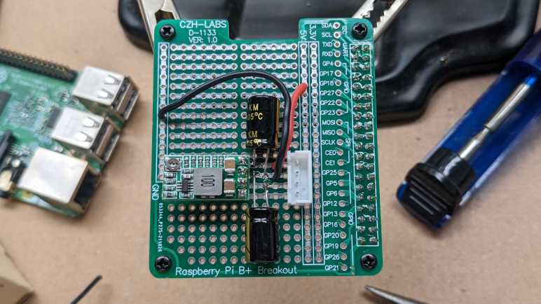
While in the process of obtaining proof that a Raspberry Pi 3 is under-powered for certain ROS processing tasks like mapping, I took a little side trip into the world of Raspberry Pi thermal management. Anyone who has pushed the limits of a Raspberry Pi would have seen a thermometer icon in the upper right corner. A quick search finds that it is put on-screen by firmware and not visible to the operating system. So when a Raspberry Pi is mounted on a robot and not attached to a monitor, we can’t see this icon. However, it is still possible to detect high temperature condition by using the command line tool vcgencmd.

raspberry-pi-logoThis tool appears to be specific to the Raspberry Pi hardware and wraps a collection of tools to query hardware information. Official documentation seems pretty slim, not even an official name. Raspberry Pi forum users hypothesize it stands for “VideoCore General Commands” which is good enough for me.

Raspberry Pi over temperature 85The first useful tool is to measure temperature. vcgencmd measure_temp will return a temperature in Celsius. This internal number is more useful than attaching an external physical temperature measurement because this internal number is what the firmware will use to decide what to do. When temperature rises above 80°C, a thermometer icon overlay with a half-full bar of red is shown on-screen and the system starts pulling itself back. When it hits the target ceiling of 85°C that icon is replaced by one with full bar of red, and the firmware becomes more aggressive throttling things down to stay below 85°C.

It’s possible to keep an eye on temperature by running the tool continuously at a regular interval, something like watch -n 0.5 vcgencmd measure_temp. But once it gets into the 80-80°C range, we can’t tell if the Pi is approaching its limits, or if those limits had been exceeded and the chip slowed itself down to stay in temperature range. For that information, we’ll need a different command.

Running vcgencmd get_throttled will return a hexadecimal number representing a set of binary flags. There is no official documentation of these bits, but a lot of Raspberry Pi user documentation link to this post as reference. If any of the throttling bits are set, the Pi is working at less than maximum potential on account of overheating. (In case that post is inaccessible, here is a copy of the table:)

 0: under-voltage
 1: arm frequency capped
2: currently throttled
16: under-voltage has occurred
17: arm frequency capped has occurred
18: throttling has occurred

Knowing throttling occurred was enough for my experiment, but if I ever need to go one step further and find out how much throttling has occurred, there are tools for that, too. It’s possible to retrieve CPU clock frequency via vcgencmd get_config arm_freq and also by looking at /sys/devices/system/cpu/cpu0/cpufreq/scaling_cur_freq. But that’s beyond the scope for today.


A 3D-Printed Enclosure to Take My LED Project On The Go

For the Connect Week event put on by Innovate Pasadena, the Hackaday LA group is hosting the “Bring-A-Hack” event where attendees are encouraged to bring projects (in any stage of completion) for show and discussion. Since I’ve been building my LTC-4627JR driver board as a learning project, I wanted to bring it in for show-and-tell.

Now I could just bring the assembled circuit board and pass it around as an inert object, but what fun would that be? I wanted to bring in something that shows it doing something, and provide some way for people to interact with the whole contraption. Looking at my parts on hand, it seemed easiest to rebuild my thermometer test project. I can have a simple Python program run on the Raspberry Pi, reading temperature from the Tux-Lab Si7021 breakout board, and sending it out to my display. That makes 3 circuit boards, plus they’ll need portable power. I will enlist my Amazon purchases: the 3-cell lithium ion battery pack protected by a S-8254A IC, and the MP1584 buck converter to translate the battery pack’s power into Raspberry Pi friendly voltage.

They present a logistics challenge. There are many parts and while it’s fine to just connect them with wires on my work table, it’s too unwieldy to carry on the Gold Line to Pasadena. I’m going to need some kind of enclosure to carry the whole thing.

To Fusion 360 we go! I just needed a simple enclosure so it was pretty fast to draw up. The bottom tray is for power: it holds the battery cells, their protection board, and the buck converter to 5 volt output. The upper tray holds the Raspberry Pi. The lid of the tray holds my custom LED circuit board, and a few clamps holds it all together. The clamps should be easily removable so I could disassemble the box to show people what’s inside.

ShowandTellBox

I had originally intended to mount the Si7021 breakout board as well, but ended up deciding it would be more fun to have it dangling out for people to play with it. Here are the layers without the clamps, so they can be taken apart and show off the insides.

IMG_5273

And here’s the “travel configuration”, with clamps holding the pieces together.

IMG_5274

This setup worked well. I was able to carry it in my backpack without worrying about tangling up or shorting out wires. Once I arrived, the project was fairly well received and lots of people had fun playing with the thermometer.

Qt Quick with PyQt5 on Raspberry Pi

QtLogoThe prime motivation for me to go through Qt licensing documentation and installing Qt Creator IDE was to explore the new UI infrastructure introduced in Qt 5 under the umbrella of “Qt Quick“. As far as I can tell, this is an entirely different system for creating user interface of a Qt application. Built with modern ideas such as OpenGL graphics acceleration for animation effects and UI layout declared with a text-based markup language QML (probably stands for Qt Markup Language.)

Up to this point my experience with building graphics user interface in Qt was with the QWidget-based infrastructure, which has a long lineage in past editions of Qt. Qt Quick is new for Qt5 and seem to share nothing in common with QWidget other than both a part of Qt5. Now that I’ve had a bit of QWidget UI work under my belt I wanted to see what Qt Quick has to offer. And this starts with a smoke test to make sure I could run Qt Quick in the environments I care about: Python and Raspberry Pi.

Step 1: Qt Creator IDE Default Boilerplate.

Once the Qt Creator IDE was up and running, I followed the Qt Quick tutorial to create a bare bones boilerplate Qt Quick application. Even without any changes to the startup boilerplate, it reported error messages complaining of missing modules. Reading the error message, I looked at the output of apt list qml-module-qtquick* and installed the ones that sound right. (From memory:qml-module-qtquick2qml-module-qtquick-controls2, qml-module-qtquick-templates2, and qml-module-qtquick-layouts)

QML CPP

Once the boilerplate successfully launched, I switched languages…

Step 2: PyQt5

The next goal is to get it up and running on Python via PyQt5. The PyQt5 documentation claimed support for QML but the example on the introductory page doesn’t quite line up with the Qt Creator boilerplate code. Looking at the Qt Creator boilerplate main.cpp for reference, I translated the application launch code into main.py. This required sudo apt install python3-pyqt5.qtquick in addition to the python3-pyqt5 I already had. (If there are additional dependencies I forgot about, look for them in the output of apt list python3-pyqt5*)

QML PyQt

Once that was done, the application launched successfully on my Ubuntu desktop machine, albeit with visual appearance very different from the C++ version. That’s good enough for now, so I pushed these changes up to Github and switched platforms…

Step 3: Raspberry Pi (Ubuntu mate)

I pulled the project git repository to my Raspberry Pi running Ubuntu Mate and tried to run the project. After installing the required packages, I got stuck. My QML’s import QtQuick 2.7 failed with error module "QtQuick" version 2.7 is not installed The obvious implication is that the version of QtQuick in qml-module-qtquick2 was too old, but I couldn’t figure out how to verify version number is indeed the problem or if it’s a configuration issue elsewhere in the system.

Searching on the web, I found somebody on stackoverflow.com stuck in the same place. As of this writing, no solution had been posted. I wish I was good enough to figure out what’s going on and contribute intelligently to the discussion!

I don’t have a full grasp of what goes on in the world of repositories ran by various Debian-based distributions, but I could see URLs flying by on-screen and I remembered that Ubuntu Mate pulled from different repositories than Raspbian. I switched to Raspbian to give that a shot…

Step 4: Raspberry Pi (Raspbian Stretch)

After repeating the process on the latest Raspbian, the Qt Quick QML test application launches. Hooray! Whether it was some configuration issue or out of date binaries we don’t know yet for sure, but it does run.

That’s the good news. Now the bad news: it launches with the error:

JIT is disabled for QML. Property bindings and animations will be very slow. Visit https://wiki.qt.io/V4 to learn about possible solutions for your platform.

And indeed, the transition between “First” and “Second” tabs were slow. Looking on the page that it pointed to, it looks like the V4 JavaScript engine used by Qt for QML applications does not have JIT compilation for Raspberry Pi’s ARM chip. That’s a shame.

For now, this excludes Qt Quick as a candidate for writing modern responsive user interfaces for Raspberry Pi applications. If I want to stick with Qt and Python, I’m better off writing Qt interfaces in the old school QWidget style. We’ll keep an eye on this – maybe they’ll add JIT support for Raspberry Pi in the future.


(The source code related to this blog post are publicly available on Github.)

Raspberry Pi Pin Initial States are a Consideration For Machine Control

As an intermediate step towards controlling the thermoforming machine with the Raspberry Pi, we populated a breadboard with some components we planned to use. A Raspberry Pi could only source a total of 50mA of power across all the IO pins, so we had it switch circuits on/off via opto-isolators that required far less current to activate. We started by using these opto-isolators to control power to LEDs. Just to see how it works and make sure nothing unexpected occurs before we start hooking up bigger things.

This proved to be wise, as it exposed some Raspberry Pi behavior we did not expect. When the Pi was powered-up, some of the LEDs glowed dimly. They’re not full bright, but they’re definitely not dark, either. Once the control program starts up and all pins are initialized to off, they go dark as expected. But there’s something going on between initial power-on and when the control program starts running.

This was important to chase down because we don’t want the machine relay to close when we’re not expecting them to close. Even worse if it occurs while the system is powering up and components are not yet in known good states. Making this an important consideration in designing our system.

A bit of web searching confirmed this startup behavior was noticed and investigated by a lot of people looking at various parts of the system. The answer was most succinctly answered by a post on the Raspberry Pi subsection of StackExchange: In the peripherals manual for the BCM2835 chip at the core of the Raspberry Pi, the power-on initial states are explicitly stated: All IO pins are configured to be input and not output. Furthermore, pins 0-8 are set with pull-up to 3.3V and pins 9-27 are pulled-down to 0V.

Looking back on the breadboard, we could confirm the explanation matches the observed behavior. The dimly lit LEDs were controlled by opto-isolators that were, in turn, connected to Raspberry Pi pins 5 and 6. None of the other isolators were controlled by pins in the 0-8 range. Since opto-isolators required so little current to operate, the weak pull-up on a pin set to input was sufficient to partially activate the circuit.

Once the cause was determined the solution was simple: move all output control out of the 0-8 range of pins. These pins would be fine for input, so the task of reading the position of a limit switch was moved to pin 5.

The resulting breadboard is visible in the attached image, and the code was changed to match the new pin assignments in this commit. After these changes, we observed no partially lit LEDs which also hopefully means no unexpected relay activity when we hook it up to the machine.

IMG_5266

Setting Up Raspberry Pi GPIO Pins For Device Control

A rough draft of the thermoformer touchscreen control panel application, witting in Python with the Qt UI framework, is now up and running. Now it is time to see how it works controlling some physical hardware. We’re going to build up to this in steps on the way towards actually controlling the thermoform machine. The first step is to have the Pi light up some LEDs as commanded by the control panel application.

I had been playing with a Microchip PIC16F18456 earlier, which can drive LEDs effortlessly. Each pin can handle 50mA which is more than enough to drive LEDs as they typically require no more than 20mA each. I had assumed the Pi would be even more capable with its onboard voltage regulators, but I thought it’d be better to check just to be safe. I’m glad I did! It turns out the pins on the Raspberry Pi has significantly lower power capability than the pins on the PIC16F18345.

The consensus on the Raspberry Pi forums says the limit is 16mA per pin, and 50mA total across all pins. A bunch of LEDs would quickly exceed the 50mA total cap. Given this, we’re going to take two baby steps at once.

We’ve known we couldn’t drive the thermoforming machine directly with Pi. And even if we could, a direct connection is not the best idea. The plan had always called for the use of opto-isolators to keep some separation between the delicate low-power circuitry on the Raspberry Pi chip and the high-power components of the machine. I just didn’t expect that bright LEDs to qualify as “high power” in this context. But since they are, we’re going to use opto-isolators to build the LED proof of concept.

The current design for the control has 9 outputs to relays, and 1 input from a limit switch. For the outputs we’re starting with the Vishay 4N32 chip to see how they work. For input, we wanted a chip that works in the reverse direction, and we’re starting with the Toshiba TLP2200. With the help of a Raspberry Pi I/O breakout board we could hook everything up on a breadboard for the first test.

IMG_5266

Learning Timers: Qt QTimer and Python threading.Timer

QtLogoWhen I interfaced my PyQt application to the Raspberry Pi GPIO pins, I ran into a classic problem: the need to perform input debouncing. The classic solution is to have the software wait a bit before deciding whether the input change is noise to be ignored or not. A simple concept, but “wait a bit” can get complicated in the world of GUI programming. When writing simple programs, we can probably get away with a literal wait by “going to sleep” for a little bit. But we don’t have that luxury in the world of GUI programming – going to sleep would freeze everything in the program. In general, users do not appreciate their UI becoming frozen and unresponsive.

Python LogoThe solution: a timer. In a Windows application, the programmer can use the operating system timer and do their “after waiting a bit” tasks in response to the WM_TIMER message. I went looking for the Qt equivalent and found several timer-related features. QTimer, QBasicTimer, and QObject::startTimer(). Thankfully, the documentation also provided an overview describing how they differ. For debounce purposes, the most fitting mechanism is a single-shot timer.

Unfortunately, when I tried to use it, I received an error message telling me I could only use Qt timer objects from code launched with QThread. Which apparently wasn’t the case with code running under the context of a QWidget within a QApplication.

I had hoped the Qt timers, working off of the QApplication event queue, would stay on the UI thread. But it appears they have to have their own QThread. I could put in more time to figure out how to get Qt timers to work, but I decided to turn to Python library instead. If I have to deal with multi-threading issues anyway, there’s no reason to avoid Python’s Timer object in the threading library.

It does mean I had to review my code to make sure it would be correct even if called from multiple threads. Since the important state are the status of the GPIO pins, they are handled by the pigpio library and the code in my app should be fairly safe. I do set a flag to avoid creating multiple Timer objects in the case of input bounce. If I cared about making sure I only ever create a single Timer, this flag should be protected against cross-thread access. But reviewing the code I decided it was OK if a few Timer ends up being created – the final result of reading the GPIO pin should still be the same even in the case of multiple Timers doing duplicate work.

(The project discussed in this blog post is publicly available on Github.)

Qt + Python = GUI for Raspberry Pi Project

Since the mission of the Raspberry Pi foundation is to “put the power of digital making into the hands of people all over the world” there is no shortage of options for programming the Pi. We have at our disposal many choices in programming languages, each with multiple application frameworks, and a large community of Raspberry Pi users for support.

QtLogoFeeling overwhelmed with options, I chose the one that best lines up with my long-term goal of getting up and running on ROS. The ROS plug-in architecture for operator GUI is rqt, based on Qt. And like much of ROS, the user has the option of working with rqt in either C++ or Python. Since I had started dabbling with ROS in Python before getting distracted, I thought the combination of Qt and Python would be a good direction to go.Python Logo

The Qt framework itself is aimed at C++ developers, and its documentation is written accordingly. Fortunately there are translation layers (language bindings) for Python. The one that seems to be the most mature is PyQt with a long list of resources, books, and online tutorials.

The next decision to make is which version to start learning. Browsing through the resources, it looks like Qt 4 is the mainstream version and Qt 5 is the new shiny. Since ROS is still in the midst of transitioning from Python 2 to Python 3, I assume rqt would be relatively old school as well. No matter which one I choose, there’ll be differences I have to tackle whenever I get around to diving deep into ROS. On the assumption that the latest and greatest versions are also the most polished (an assumption based on how Python 3 cleaned up a lot of architectural messiness of Python 2) I thought I’d start learning with the latest releases and make adjustments later as I need to.

So: Qt 5 and Python 3 it is, with the help of PyQt5 binding. Which is easily installed on a Raspbian Stretch system by installing the packages “pyqt5-dev” and “pyqt5-dev-tools”.