Duet Display External Monitor: High Resolution and Features to Match High Price

Having multiple monitors is a great luxury. Not everyone appreciates it, but those that get used to it miss it greatly when traveling. It’s the biggest downside of using a MacBook Air as the travel laptop. It is smaller and lighter than the homebuilt external monitor, making it kind of silly to use them together. When light weight and portability is important enough to take the MacBook Air, we’ll also need the external screen to be equally portable.

The search for a thin-and-light external screen companion started with units that receive both power and data via the USB port. Sadly most of them offered only a low 1366×768 resolution at the starting $100 price range. Very few offer 1920×1080 resolution and they are in the $200 range. To get resolution any higher than that, we’ll need an iPad running Duet Display. Which means spending >$300. The good news is, for that price, the system worked very well with only two caveats:

First, Duet uses a proprietary protocol that requires a special driver running on the computer to talk to the app running on the iPad. Installing this driver triggered several warnings from MacOS and required explicit authorization to run non-Apple code signed with the name Rahul Dewan. A web search indicated this was the name of founder and CEO of Duet Display, so that matches, but it’s still a scary action from a security perspective.

Second, application windows could not span the two monitors. They can be dragged from one to the other, but each window will show only on one monitor. If a window is dragged to straddle the divide, only half of the window will show on one monitor, and the other half is not visible anywhere.

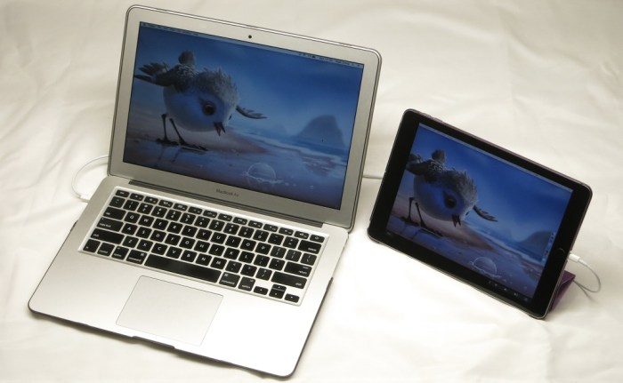
Other than that constraint, Duet Display works well to make an iPad (2017, Model A1822) serve as an external monitor for a MacBook Air (13-inch, early 2014). The speed and responsiveness are great. So far, the performance has been indistinguishable from an external monitor connected to the MacBook Air via HDMI.

It even offers something not available on other USB external monitors: the ability to hook into Apple’s Touch Bar feature and show the bar on the iPad. Even for Apple computers that aren’t equipped with the Touch Bar.

Duet+iPad has turned out to be the most expensive of the external MacBook monitor options, but it makes a compelling case to justify its price. High resolution, super lightweight, and naturally the iPad is still a perfectly good tablet when detached from the computer.

Duet in Action


SGVLUG: Custom Computer Projects

Last night I had the opportunity to present my Luggable PC, FreeNAS Box, and Portable External Monitor projects to the San Gabriel Valley Linux User’s Group. Though the projects themselves have only minimal relation to Linux, the spirit of customization and project sharing fits well with the Linux open source ethos.

SGVTalkTitle

I hauled in all the latest versions of my projects. Plus all the earlier drafts and revisions that have yet to be disassembled and pitched. More visual aids is always better than less and they proved quite popular after the talk concluded and people came up to look over the projects up close.

Some of the audience found the topic engaging and stayed after the talk discussing aspects that didn’t make it into the talk and offered ideas for future exploration. Some of those ideas were already on my to-do list and some are novel ideas I should explore.

A few people left early, whether they had other obligations or they got bored I might never know.

I don’t have a lot of public speaking experience so this was a great opportunity for me to get some practice in a low-pressure environment in front of a like-minded crowd. At the moment I’m not planning to go work in a mega corporation again. I might not need good presentation skills in a small business, but if I want to get entrepreneurial and start my own business, I will definitely need presentation skills.

This was good practice, building up the public speaking skill one bit at a time.

Much like my design and fabrication skills.


Portable External Monitor v3 + Raspberry Pi

The work for portable external monitor (version 3) is winding down and now it’s time for it to get to work. First up: help configure a Raspberry Pi to run the ARM port for ROS Kinetic.

PEMv3vitPi

This is the culmination of several different projects documented on this blog. Most obvious is the portable external monitor project. Which incorporated LED light design from the edge light investigation project. The 12 volt power from the LCD panel driver board is tapped to power the Raspberry Pi, stepped down to 5 volts by the MP1584 voltage step-down converter recently purchased on Amazon. The Raspberry Pi is housed in the 3D-printed enclosure that was one of my first projects in Onshape.

And on the software side, I’m just getting started on learning the Robot Operating System. This specific configuration will help me learn how to set up and run a ROS network across multiple nodes, one being my desktop PC and the other this Raspberry Pi.

Many projects, combined to become whole new projects!

Portable External Monitor v3 LEDs

Before we wrap up version 3 of the Portable External Monitor project, we’ll add a purely aesthetic finishing flair: some gratuitous LEDs! This is the first opportunity to apply what I’ve learned from the LED edge lighting experiments conducted a few weeks ago.

When I first received and examined the LCD panel driver board (*) from the Amazon vendor, I noticed that a few connectors were unused. One of them caught my attention: it appears to be a way to share the 12 volt power source without the need to perform any soldering work on the circuit board.

12VPower

A little Google search determined the connectors on the other side of the circuit board to be 4-pin JST PH-type connectors. So back to Amazon I go to obtain the connectors (*) for this LED project.

The slots for the LEDs were cut into the spine for the PEMv3 core. It was easy to place the LEDs in those slots and wired them up to the JST PH connector in series with appropriate current limiting resistors.

LEDCutout

When turned on and running, PEMv3 was already pretty brightly lit: the fluorescent back light for the panel emits light in many other directions. It is visible from multiple locations on the side, and also visible across most of the back side. Adding these LEDs (green, to match the 6mm acrylic used in the enclosure) is fairly redundant but succeeded in making everything even brighter.

Maybe I’ll find the brightness annoying in due time. But for now, version 3 of the Portable External Monitor shines bright. May it shine for a long and happy time.

Or until I decide to build version 4. Whichever comes first.


(*) Disclosure: As an Amazon Associate I earn from qualifying purchases.

Portable External Monitor v3 Enclosure

Once we have a compact core built for the portable external monitor project, it becomes relatively easy to design and build an enclosure around it. Mostly an acrylic box that functions as a sleeve into which the core can fit, but also some additional components so we can have an integrated stand.

Once the individual parts are cemented together, a quick test to verify the parts fit.

PEMv3EncTestClosed

PEMv3EncTestOpen

Then we install the core.

PEMv3AssembledClosed.JPG

PEMv3AssembledOpen

Two problems were immediately apparent.

First problem: movement along the threaded rods were not constrained. In the ideal CAD world, the parts only hinged about a single axis. In the real world, they slide all over the place because I forgot to design in anything to prevent that movement.

PEMv3Chaos

Second problem: The threaded rod at the top did not function as designed. Not only did it fail to clip in to the top and hold things closed as I had hoped, it also blocked access to the ports in the open position.

PEMv3PortsBlocked

To constrain movement along the threaded rods, I added a few 3D-printed parts to the base. I also replaced the upper rods of the stand with 3D printed parts for better alignment with the adjacent rail and eliminate the need for the threaded rod that ended up blocking the port. It still doesn’t clip to the rail and hold everything closed like I hoped, but it is a big step forward in functionality.

PEMv3DP

Once that is all done, the portable external monitor became far more portable. While maximum thickness stayed about the same, most of version 3 was thinner with only the main circuit board area reaching that maximum thickness. In contrast, all of version 2 were of the same maximum thickness. We shrunk along the remaining physical dimensions: the height shrunk by 1cm, and the width shrunk by a dramatic 6cm.

PEMv2v3

All of the above combined to allow PEMv3 to fit in my JanSport backpack. And carrying it will be far less of a chore now due to its significantly lighter weight. The fully equipped PEMv3 enclosure is now roughly half the weight at 4 lb. It is in fact lighter than even just the acrylic portions of PEMv2, which weighs in at 5 lb empty of electronics.

All those advances, and we have an integrate stand as well! Version 3 should be a far more usable unit than version 2 was.

Portable External Monitor v3 Screen and Components Core

Now that the unused bracket has been cut out of the way, it’s time to pack components into that newly freed space. Due to the CFL backlight power wire, there’s not a lot of room for creativity to place the CFL voltage converter board. It ends up approximately at the same place as the old dead CFL driver board where the bracket used to be. That left enough room on either side of the driver board: the buttons circuit board on the left, and the IR receiver on the right.

One unfortunate aspect of these aftermarket circuit boards is that they’re designed towards ease of construction, allowing easy mixing-and-matching components. Large components, especially the cable connectors, make it easy to snap things together. But the large connectors work against us when we’re trying to pack everything tightly. There’s a good reason they don’t use these types of parts when building thin and light laptops!

This hampers our effort packaging the buttons board and the IR receiver board. Everything is on one side of the circuit board for ease of construction, working against a compact layout. For example, we want the user-facing bits (buttons and IR receiver) on one side of the circuit board, and the cables on the back side for connection, but that’s not how they were built.

Building something out of laser-cut pieces means the Z axis is constrained by the thickness of the acrylic stock available. That plus the inconveniently placed cables and connectors made the whole exercise a challenging game of 3D jigsaw puzzle. Here’s my solution for Portable External Monitor, version 3:

PEMv3Core

While the components aren’t all on a single sheet of acrylic, we got close enough that it’s actually a pretty tightly integrated unit. Now this core unit, consisting of the screen plus supporting circuit boards, needs an enclosure around them.

PEMv3Core

Portable External Monitor v3: Trim Unused Bracket

For the portable external monitor project, version 3 (PEMv3) , we want to pack our components more tightly together to create a compact package. The most inconvenient barrier to the goal is the old back light driver board mounting bracket. While the circuit board itself was already dead when I got the laptop and promptly removed, the bracket for the driver board was still present during PEMv1 and PEMv2. The aftermarket back light driver board is significantly larger than the original Dell part and would not fit in the bracket. I had originally hoped the bracket can be recruited into a new role but none had ever come up.

So now it is time to trim off the bracket.

The front part of the bracket is riveted to the thin metal bezel of the LCD panel. The rivet makes it easy to remove with a Dremel grinding tool, but I was concerned about the potential for metal particles to damage the panel. I spent more time covering and wrapping the rest of the panel than I did removing the rivets.

LCD bezel rivet

The rear part of the bracket is part of the panel mounting frame. Since there were no electronics here, I didn’t have to worry as much about damage. I will need to thoroughly clean up the work piece afterwards to minimize the number of particles that are still sticking, but I didn’t have as much risk while doing the actual cutting.

Frame Before

I chose to minimize the cut length which removed more metal than necessary because the shortest cut connected the two large bottom holes. We should still have enough structural strength and mounting holes for the frame to be useful.

Frame After

With the old bracket out of the way, it’s time to pack our components into the space previously occupied by the bracket.


Portable External Monitor v2 Problems To Fix in v3

And now, back to the portable external monitor (PEM) project. Version 2 has been in use for several weeks, called into duty when I needed a screen. It was used to help me install and smoke test ROS on a Raspberry Pi 3. It was also used for the FreeNAS box, which was ideal because FreeNAS only needs a screen briefly for setup.

Functionally speaking the portable external monitor has been working well. But the physical form factor left room for improvement: it wasn’t as portable as I would like.

The first part of the problem is weight: PEMv2 was built by stacking sheets of acrylic that had holes cut out to make room for components. There’s no fundamental reason why this subtractive construction technique had to be heavy. But in practice, holes were cut only when needed to make room. The result is a lot of excess acrylic. Acrylic is not super heavy, but it all adds up to just over 8 pounds which is ridiculously overweight for a 15″ screen.

The second part of the problem is size: PEMv2 was intended to fit within the width and height of my JanSport backpack. When assembled, I had a facepalm moment: it does not actually fit into the backpack because PEMv2 is rectangular and the backpack is not. The top of the backpack is rounded, with no room for PEMv2 top corners.

BackpackPEMv2

Lastly: while PEMv2 was thick enough to stand upright on its edge, it is easily tipped over and the upright vertical screen angle is not very ergonomic. We can definitely do better.

PEMv3 will try to address all of the above issues. To minimize physical volume, we’ll need a more compact way to package all the components. We’ll need to build our enclosure using less acrylic to further reduce weight. And we’d like to have an integrated stand that can securely prop up the screen at a better viewing angle

Acrylic Lights: Infinity Mirror

I’ve played with putting lights in my 3D-printed creations for glowing illumination effects. There were limits to what I could do with 3D printing, though, because printing with a clear filament does not result in a clear object. In contrast, acrylic is clear and works as a light guide with a lot of possibilities.

I’ve noticed a few attention-getting light effects in my acrylic projects to date, most of them created by happy accident. The acrylic box with external fixture made good use of external light. The Portable External Monitor version 2.0 was built from stacks of acrylic sheets: its fluorescent back light reflected between the layers like an infinity mirror.

PEMv2_InfLights

This effect was on my exploration to-do list for the future, but I moved it to the top of the list after seeing surprisingly good results on the FreeNAS Box v2 enclosure.

I had planned for it to have the standard PC status LEDs: one for power, and one for disk activity. The acrylic plate for motherboard mounting spacer also had two cutouts for 3mm LEDs along the center line. The red hard drive activity light is to be mounted high, and the blue power light mounted down low. The idea was for the blue light to illuminate the top edge of the plate. When there is hard drive activity, red LED will light up the center of that edge, and it should blend to purple with the power light. Both LEDs were blocked from direct view by the motherboard, so all we should see is a nice soft glow emitting from behind the motherboard.

FreeNASv2LightPlan

That was the plan, the reality was different. The red activity light worked as expected: when there is disk activity, the center of the top edge had a little red glow.

The blue LED decided to ignore my “nice soft glow” plan and put on an extravagant light show. It didn’t just light the top edge, it lit every edge of that acrylic sheet and had plenty of extra light energy to throw on the surrounding shelving.

FreeNASv2_LightsAbove

Here’s a close-up of the sideways illumination.

FreeNASv2_LightsSide

The many rays visible in the side illumination, as well as the lines making up the top illumination, indicate infinity mirror action going on inside that sheet. It wasn’t directly visible, and probably very difficult to photograph even if so. Without internal reflections, the blue light would have just gone straight up. But with the smooth surfaces and edges of the acrylic reflecting inside the sheet, the light of a single LED bounced around, found different angles, and was emitted in many more directions.

This LED illumination effect warrants further investigation. It is a happy accident that I fully intend to learn from, and put into future acrylic projects.

I want every acrylic project to look this awesome!


Portable External Monitor 2.0: Stacking Plates

Enclosure2_CAD
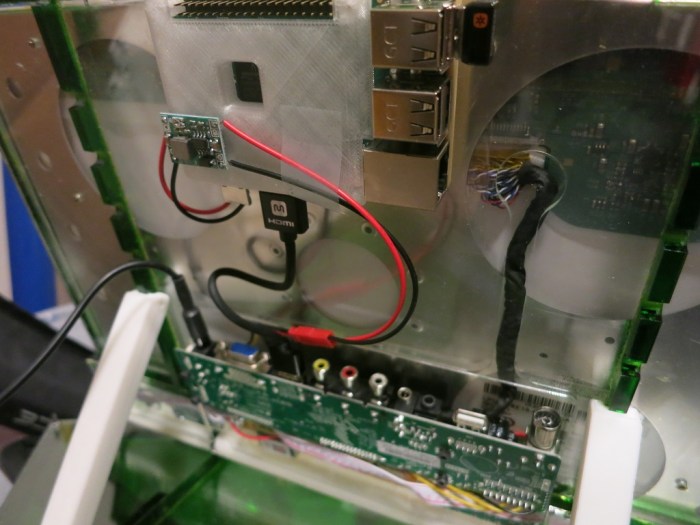
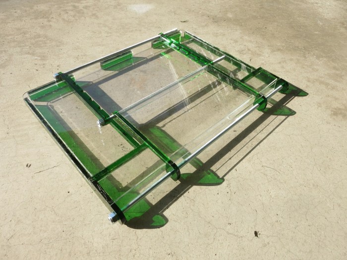
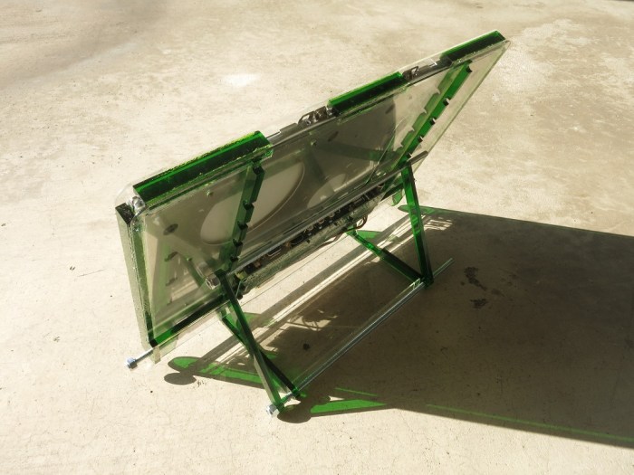
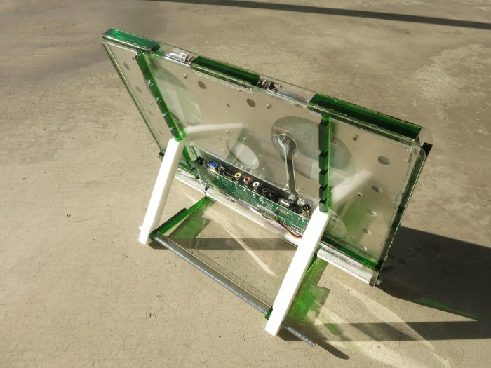
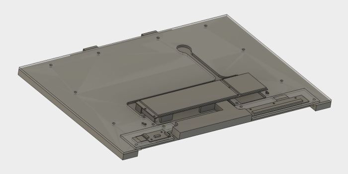
Portable External Monitor version 2.0 (PEM2) explored a different construction technique from PEM1. Instead of building a box by assembling its six side pieces (top, bottom, left, right, front back) the box is built up by stacking sheets of acrylic.

With this construction technique, it is much quicker to place components in arbitrary locations in 3D space. Control along the X/Y laser cutting axis are trivial. Control in the Z axis takes a little more effort. The components can be aligned to the thickness of the sheet of acrylic, but if that’s not enough, it is possible to use engraving operations to precisely locate the component in Z.

In contrast, when we want to locate components inside a box at a specific coordinate, we’ll have to design additional pieces – supports and brackets – to mount the item at the appropriate location in the box.

It is also very easy to assure alignment between the parts of the box. Cut a few fastener holes at the same location across all the sheets. After they are stacked up, inserting the fasteners to align all the sheets.

The downside of this approach is that it is very wasteful of material. Each layer will consume an acrylic sheet of the overall X and Y dimensions. And if we only cut away the parts we need for the components, there is potential for a lot of unnecessary acrylic in the final assembly. They add weight without usefully contributing to the structure. Putting in the design time to cut away those parts reduces the time savings of this technique, as it starts approaching the work needed to design supports and brackets in an empty box.

If there’s an upside to the wasted material, it is the fact that this glue-less technique can be easily disassembled. When we’re done evaluating this prototype, every sheet of acrylic can be reused as material for future (necessarily smaller) projects.

Lesson learned: This “stacking plates” construction technique offer a trade off of reducing design time and effort at a cost of reduced material usage efficiency.

Enclosure2_Complete

Thread Tapping Failure and Heat-Set Threaded Inserts

Part of the design for PEM1 (portable external monitor version 1.0) was a VESA-standard 100 x 100mm pattern to be tapped with M5 thread. This way I can mount it on an existing monitor stand and avoid having to design a stand for it.

I had hand tapped many M5 threads in 3D printed plastic for the Luggable PC project, so I anticipated little difficulty here. I was surprised when I pulled the manual tapping tool away from one of the four mounting holes and realized I had destroyed the thread. Out of four holes in the mounting pattern, two were usable, one was marginal, one was unusable.

AcrylicTappedThreads
Right: usable #6-32 thread for circuit board standoff. Left: Unusable M5 thread for VESA 100 monitor mount.

A little debugging pointed to laser-cutting too small of a hole for the tapping tool. But still the fact remains tapping threads in plastic is time-consuming and error-prone. I think it is a good time to pause the project and learn: What can we do instead?

One answer was literally sitting right in front of me: the carcass of the laptop I had disassembled to extract the LCD panel. Dell laptop cases are made from plastic, and the case screws (mostly M2.5) fasten into small metal threaded inserts that were heat-set into the plastic.

Different plastics have different behavior, so I thought I should experiment with heat-set inserts in acrylic before buying them in quantity. It doesn’t have to be M5 – just something to get a feel of the behavior of the mechanism. Where can I get my hands on some inserts? The answer is again in the laptop carcass: well, there’s some right here!

Attempting to extract an insert by brute force instead served as an unplanned demonstration of the mechanical strength of a properly installed heat-set insert. That little thing put up quite a fight against departing from its assigned post.

But if heat helped soften the insert for installation, perhaps heat can help soften the plastic for extraction. And indeed, heat did. A soldering iron helped made it far easier to salvage the inserts from the laptop chassis for experimentation.

Portable External Monitor 1.0

LCD Enclosure 1 pieces
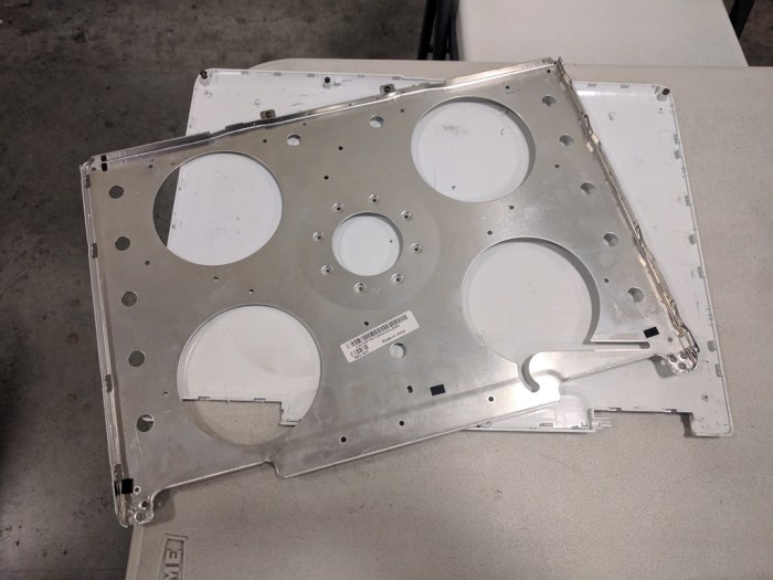
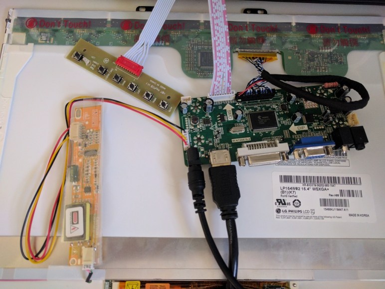
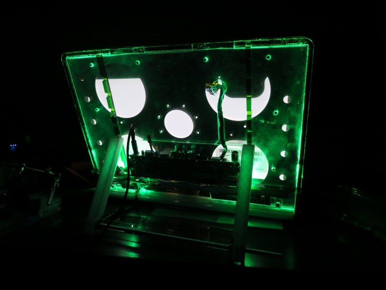
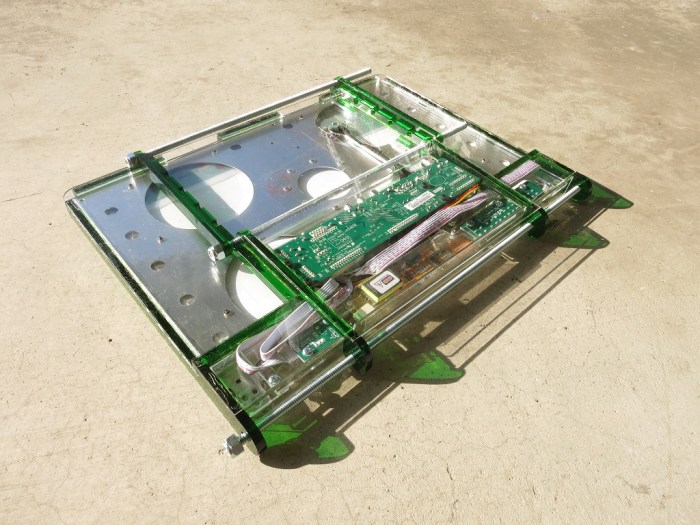
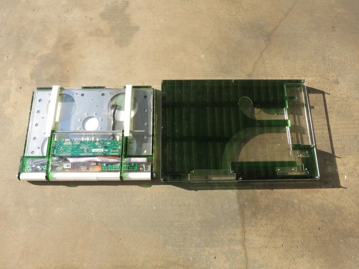
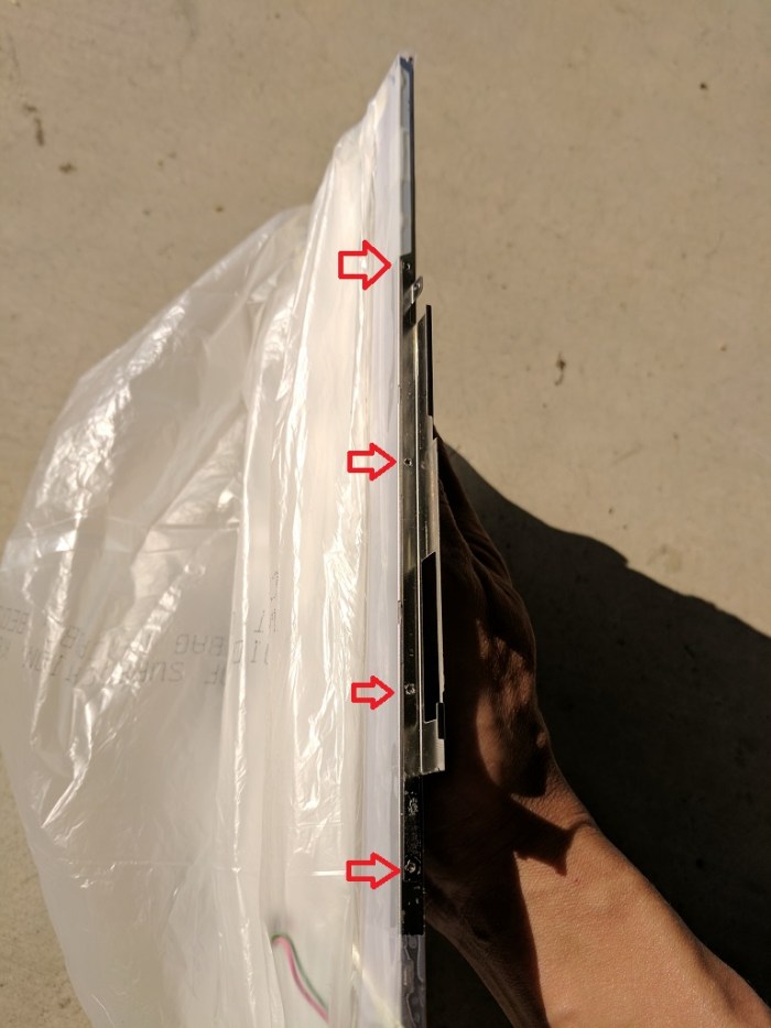
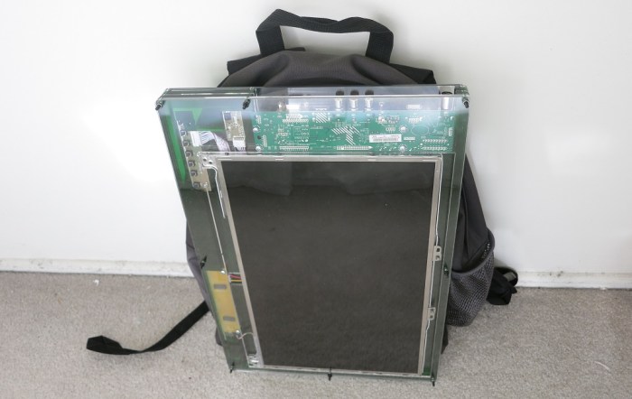
Once the LCD panel and matching frame had been salvaged from the laptop, it’s time to build an enclosure to hold it and the associated driver board together. Since this was only the first draft, I was not very aggressive about packing the components tightly. It’s merely a simple big box to hold all the bits checking to see if I have all the mounting dimensions for all the circuit boards correct.

It was also the first time I had the chance to try acrylic sheets in a color other than clear. There was a dusty stack of 6 mm green acrylic that I enlisted into this project. Since this is just an early draft project, I valued ease of construction over appearance or strength (6 mm is more than sufficient) and so I used the interlocking tab design for self-aligning assembly.

The resulting box was functional, but not very interesting from a design viewpoint. I just wanted to prove that all the components worked together before I proceeded to the next draft.

I did not design this enclosure to stand by itself. Instead, I had designed this enclosure with a VESA standard 100x100mm mounting pattern in the back and intended to tap those laser-cut holes to take M5 fasteners. Once so prepared, I can mount this enclosure on any existing stand that conforms to the standard. That little design detail – independent of the LCD panel and driver board – sent me off on a little side exploration of plastic construction techniques.

That is a story for the next update.

LCD Panel Frame From Laptop Lid

Drilling out plastic rivets
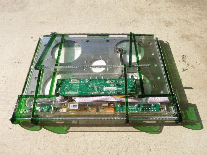
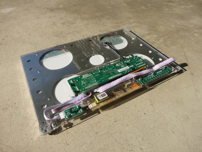
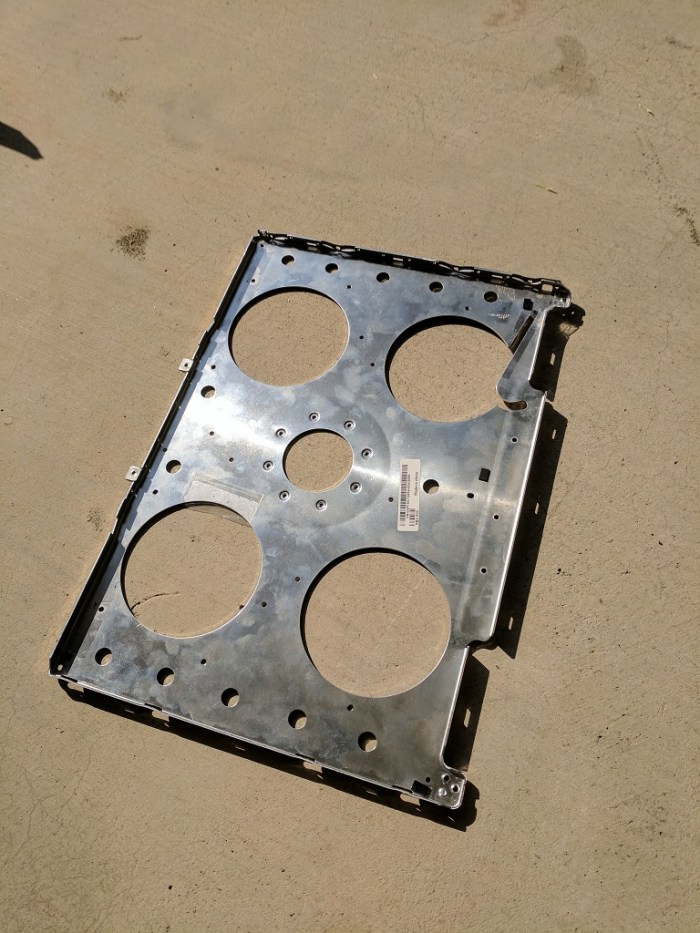
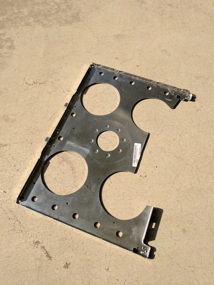
My Luggable PC display was a LCD panel I had salvaged from an old laptop, which I’m doing again for this external monitor project. When I pulled the Luggable PC panel out of the old laptop, I left most of the associated mounting hardware behind. During the Luggable PC project I wished I had also preserved the old mounting hardware.

The first reason is dimension data. When I mounted the screen to my Luggable PC, I had to measure the panel and design my frame to match. A Dell engineer did this work years ago, and when I threw away the mounting hardware, I threw that away as well.

The second reason is strength. A LCD panel is fragile, but when backed with its sheet metal frame, it becomes quite a bit stronger. This is usually a worthwhile trade off against the increased size and weight.

The third reason, less obvious than the previous two, is to manage heat. The back light assembly across the bottom of the screen would get quite hot when the panel is just sitting by itself. However, when the panel is mounted in its frame, the frame served a secondary purpose as heat sink.

The metal frame I want to reuse is attached to the plastic outer cover of the laptop lid. The attachment is done via small plastic rivets: bits of the plastic lid cover melted into the metal frame. Pulling off the frame with brute force is likely to bend and damage the frame, so the assembly is put under the drill press. After cores of all of the plastic rivets were drilled out (above), the metal frame easily pops off the plastic lid cover (below).

Frame freed

The metal frame can now be used to build the rest of the enclosure. The frame can be cut, drilled, and generally manipulated in ways that I would never do to the LCD panel itself. And when I’m done with all the prep work, the panel itself will drop right in to the frame. This should be much easier than what I had to do for the Luggable PC screen.

Portable External Monitor Project

Thanks to a friend’s generous donation of a nonfunctional Dell Inspiron E1505, I have another LCD panel to play with. (And distract me from FreeNAS Box project.) The eventual ambition is to upgrade my Luggable PC to a multiple-monitor system but as a first step, I’ll learn to work with the new panel by turning it into a portable external monitor. If phase 1 is successful, it becomes an optional additional accessory I can lug alongside the Luggable PC. Then, if I’m feeling ambitions, I can move on to phase 2 of integrating everything into a multi-monitor Luggable PC.

The first order of business is to extract the panel and look at its specifications. Dell laptops around that vintage offer resolution as low as 1024×768, which wouldn’t even be worth the effort to resurrect. Fortunately, this LG Philips LP154W02 panel has a decently respectable 1680×1050 resolution.

Since the computer doesn’t work, next I have to see if the panel does. Off to Amazon to look for boards that claim to drive this panel. The first board (*) pictured here was able to present all the right info to a computer, and it can power the back light, but no picture showed on screen. At this time I was worried – did I get a bum board, or is the display dead?

After some diagnostic chatter with the seller, I was pointed to another board they carried. The first board was computer-focused, the second board was more TV and media focused. The upside is that it worked. The downside is that it seems to have trouble preserving 1:1 pixel information at 1680×1050. I wonder if its media-focused nature meant it up scale all signals to 1080p and then down sample to the panel resolution. That would explain the minor visual artifacts.

The artifacts does take a bit away from the success. But it’s lit, it shows a picture, and that’s good enough to proceed.


(*) Disclosure: As an Amazon Associate I earn from qualifying purchases.