LIN Bus The Little Sibling Of CAN Bus

Today I learned about existence of Local Interconnect Network or LIN bus. It is a set of specifications defining a network communication system describing everything from raw voltage levels up to logical communication data protocol. A LIN network has up to sixteen devices: one controller and up to fifteen peripherals, and they communicate via asynchronous serial over a shared wire. At a high level, there’s a lot of resemblance to how serial bus servos work, but LIN came from the automotive field.

As car components got more sophisticated, basic on/off or analog voltage was no longer enough to convey status. They needed an actual data network protocol, and the industry has settled on CAN bus. While capable and robust, CAN bus is overkill for basic functions. LIN bus is a simpler protocol that trades capability for less expensive implementation hardware. A focus on simplicity meant the LIN steering group decided their job here was done and is now a mature standard also known as ISO 17987.

Based on my limited reading, I understand the division of labor for an illustrative modern car driver’s door would be something like this:

  • A host controller connected to the car’s CAN bus communicating with the rest of the car, and connected to other devices inside the door via LIN bus.
  • A microcontroller monitors all the power window switches and report their status to the door host via LIN.
  • A microcontroller manages the power window motor based on commands received from door host via LIN.
  • Repeat for power door locks, and power mirrors.
  • Other sensor inputs like whether door latch is closed.
  • Other control outputs like illuminating puddle lights.

Given the close proximity of these devices to each other inside the door, full signal integrity robustness of CAN bus was not strictly necessary. LIN bus modularity means fewer wires. For example, wires that would otherwise be necessary if the host controller had to monitor each power window switch individually could now be replaced by a single LIN data wire. It also simplifies adding/removing functionality for higher/lower trim levels in a product line, and reduce cost of adapting to regional differences like left- or right-hand drive.

That’s all great for automobile manufacturers. But since LIN bus is simpler than CAN bus, it also lowers the barrier to repurposing automotive components for hobbyist projects. A quick look on Arduino forums found several threads discussion LIN bus devices, and there exists affordable breakout boards (*) to interface with microcontrollers. This could be an entryway into a lot of fun.


(*) Disclosure: As an Amazon Associate I earn from qualifying purchases.

Commodity Plastic Fasteners (8mm Diameter)

I have several projects on the to-do list for my 2004 Mazda RX-8, but I had been procrastinating because I hated dealing with its plastic fasteners. These are designed to fit in holes roughly 8mm in diameter and hold two or more pieces together. Usually at least one of those pieces is a flexible body trim panel.

They are made from two pieces: an center portion that pushes against the outer portion so the latter expands to hold the fastener in place.

Here’s what the head looks like in the fastened state.

In theory, we release this fastener by a quarter-turn of a Philips-head screwdriver.

This pushes a few wedges/ramps against each other and pops the center free, allowing the outer portion to contract and letting us pull the fastener out of its hole.

In practice, years of road dirt and grime jams up the works so the center doesn’t want to turn. Applying more torque risks stripping the slot, and the typical technique to avoid cam-out is to push my screwdriver harder inward. This force directly defeats the purpose of the turn, which is to pop the center outward! I’ve always felt it was a bad design to put such forces in direct opposition to each other. Despite my efforts to avoid damage I would end up stripping the inner slot and have to find some other way to release the fastener. This usually ends up damaging the fastener (this one’s outer ring is cracked) as well as the panels it had fastened to.

I’m not sure if these are factory original Mazda parts, but I do know I have came across multiple different fasteners on my car. Some of them might have been fitted by mechanics who have worked on my car over the past two decades. I understand why they would perform such substitution, and I will follow their lead.

My criteria was to find something advertised for 8mm holes and suited for outdoor environment applications. These are pretty generic commodity parts used across multiple industries for different purposes, but there doesn’t seem to be a commonly agreed upon name for these things. I settled on an Amazon product that just incorporated a bunch of different into its lengthy title: 200PCS 8mm UTV ATV Fender Push Clips with Fastener Removal Tool, Nylon Body Rivets Fasteners Clips Compatible with Polaris Ranger RZR Can Am Kawasaki Teryx Honda Suzuki Sportsman (*)

And the best part: this design doesn’t require self-defeating forces to remove. Again this center component is designed to pop out, but this time it’s not the turn of a Philips screwdriver. Instead, this has side slots for me to pry against to pop them out.

On the downside, these lowest-bidder items are definitely not as nicely made, with crude plastic injection molding flash all over. Diameter of the head is not as large as my original fasteners, and length is slightly longer. Despite these differences they seem sufficient due to the loose tolerance nature of the application. They are good enough for today but the real test will come years down the line when I try to release one seized up from years of dirt and grime. I figured even if it doesn’t release, I could take a large pair of diagonal cutters and cut it off. I know how to get plenty of replacements.

Having that option is great, because it greatly eased projects that require dealing with such plastic fasteners. And I already have one on my hands: tracking down a coolant leak.


(*) Disclosure: As an Amazon Associate I earn from qualifying purchases

Updating Ubuntu Battery Status (upower)

A laptop computer running Ubuntu has a battery icon in the upper-right corner depicting its battery’s status. Whether it is charging and if not, the state of charge. Fine for majority of normal use, but what if I want that information programmatically? Since it’s Linux, I knew not only was it possible, but there would also be multiple ways to do it. A web search brought me to UPower. Its official website is quite sparse, and the official documentation written for people who are already knowledgeable about Linux hardware management. For a more beginner-friendly introduction I needed the Wikipedia overview.

There is a command-line utility for querying upower information, and we can get started with upower --help.

Usage:
  upower [OPTION…] UPower tool

Help Options:
  -h, --help           Show help options

Application Options:
  -e, --enumerate      Enumerate objects paths for devices
  -d, --dump           Dump all parameters for all objects
  -w, --wakeups        Get the wakeup data
  -m, --monitor        Monitor activity from the power daemon
  --monitor-detail     Monitor with detail
  -i, --show-info      Show information about object path
  -v, --version        Print version of client and daemon

Seeing “Enumerate” as the top of the non-alphabetized list told me that should be where I start. Running upower --enumerate returned the following on my laptop. (Your hardware will differ.)

/org/freedesktop/UPower/devices/line_power_AC
/org/freedesktop/UPower/devices/battery_BAT0
/org/freedesktop/UPower/devices/DisplayDevice

One of these three items has “battery” in its name, so that’s where I could query for information with upower -i /org/freedesktop/UPower/devices/battery_BAT0.

  native-path:          BAT0
  vendor:               DP-SDI56
  model:                DELL YJNKK18
  serial:               1
  power supply:         yes
  updated:              Mon 04 Sep 2023 11:28:38 AM PDT (119 seconds ago)
  has history:          yes
  has statistics:       yes
  battery
    present:             yes
    rechargeable:        yes
    state:               pending-charge
    warning-level:       none
    energy:              50.949 Wh
    energy-empty:        0 Wh
    energy-full:         53.9238 Wh
    energy-full-design:  57.72 Wh
    energy-rate:         0.0111 W
    voltage:             9.871 V
    charge-cycles:       N/A
    percentage:          94%
    capacity:            93.4231%
    technology:          lithium-ion
    icon-name:          'battery-full-charging-symbolic'

That should be all the information I need to inform many different project ideas, but there are two problems:

  1. I still want the information from my code rather than running the command line. Yes, I can probably write code to run the command line and parse its output, but there is a more elegant method.
  2. The information is updated once every few minutes. This should be frequent enough most of the time, but sometimes we need more up-to-date information. For example, if I want to write a piece of code to watch for the rapid and precipitous voltage drop that happens when a battery is nearly empty. We may only have a few seconds to react before the machine shuts down, so I would want to dynamically increase the polling frequency when the time is near.

I didn’t see a upower command line option to refresh information, so I went searching further and found the answer to both problems in this thread “Get battery status to update more often or on AC power/wake” on AskUbuntu. I learned there is a way to request status refresh via a Linux system mechanism called D-Bus. Communicating via D-Bus is much more elegant (and potentially less of a security risk) than executing command-line tools. The forum thread answer is in the form of “run this code” but I wanted to follow along step-by-step in Python interactive prompt.

>>> import dbus
>>> bus = dbus.SystemBus()
>>> enum_proxy = bus.get_object('org.freedesktop.UPower','/org/freedesktop/UPower')
>>> enum_method = enum_proxy.get_dbus_method('EnumerateDevices','org.freedesktop.UPower')
>>> enum_method()
dbus.Array([dbus.ObjectPath('/org/freedesktop/UPower/devices/line_power_AC'), dbus.ObjectPath('/org/freedesktop/UPower/devices/battery_BAT0')], signature=dbus.Signature('o'))
>>> devices = enum_method()
>>> devices[0]
dbus.ObjectPath('/org/freedesktop/UPower/devices/line_power_AC')
>>> str(devices[0])
'/org/freedesktop/UPower/devices/line_power_AC'
>>> str(devices[1])
'/org/freedesktop/UPower/devices/battery_BAT0'
>>> batt_path = str(devices[1])
>>> batt_proxy = bus.get_object('org.freedesktop.UPower',batt_path)
>>> batt_method = batt_proxy.get_dbus_method('Refresh','org.freedesktop.UPower.Device')
>>> batt_method()

I understood those lines to perform the following tasks:

  1. Gain access to D-Bus from my Python code
  2. Get the object representing UPower globally.
  3. Enumerate devices under UPower control. EnumerateDevices is one of the methods listed on the corresponding UPower documentation page.
  4. One of the enumerated devices had a “battery” in its name.
  5. Convert that name to a string. I don’t understand why this was necessary, I would have expected the UPower D-Bus API should understand the objects it sent out itself.
  6. Get an UPower object again, but this time with the battery path so we’re retrieving an UPower object representing the battery specifically.
  7. From that object, get a handle to the “Refresh” method. Refresh is one of the methods listed on the corresponding UPower.Device documentation page.
  8. Calling that handle will trigger a refresh. The call itself wouldn’t return any data, but the next query for battery statistics (either via upower command line tool or via the GetStatistics D-Bus method) will return updated data.

Window Shopping vorpX

Thinking about LEGO in movies, TV shows, and videogames, I thought the natural next step in that progression was a LEGO VR title where we can build brick-by-brick in virtual reality. I didn’t find such a title [Update: found one] but searching for LEGO VR did lead me to an interesting piece of utility software. The top-line advertising pitch for vorpX is its capability to put non-VR titles in a VR headset.

It’s pretty easy to project 2D images into a VR headset’s 3D space. There are lots of VR media players that projects movies on a virtually big screen, and vorpX documentation says it can certainly do the same as the fallback solution. But that’s not the interesting part, vorpX claims to be able to project 3D data into a VR headset in 3D. This makes sense at some level: games engines are sending 3D data to our GPU to be rendered into a 2D image for display on screen. Theoretically, a video driver (which vorpX pretends to be) can intercept that 3D data and render it twice, once for each eye in our VR headset.

Practically speaking, though, things more complicated because every game also has 2D elements, from menu items to status displays, that are composited on top of that 3D data. And this is not necessarily a linear process, because that composited information may be put back into 3D space. Back-and-forth a few times, before it all comes out to a 2D screen. Software like vorpX would have to know what data to render and what to ignore, which explains why games need individual configuration profiles.

Which brings us to the video I found when I searched for LEGO VR: YouTube channel Paradise Decay published a video where they put together a configuration for playing LEGO Builder’s Journey in a Oculus Rift S VR headset via vorpX. Sadly, they couldn’t get vorpX working with the pretty ray-traced version, just the lower “classic” graphics mode. Still, apparently there’s enough 3D data working for a sense of depth on the playing field and feeling of immersion that they’re actually playing with a board of LEGO in front of them.

For first-person shooter type of games using mouse X/Y to look left-right/up-down, vorpX can map that to VR head tracking. When it’s not a first-person perspective, the controls are unchanged. VR controller buttons and joysticks can be mapped to a game controller by vorpX, but their motion data would be lost. 6DOF motion control is a critical component of how I’d like to play with LEGO brick building in VR, something vorpX can’t give me, so I think I’ll pass. It’ll be much more interesting to experiment with titles that were designed for VR, even if they aren’t official LEGO titles.

FreeCAD Notes: Workbenches

After deciding I’ve had enough of a distraction from learning FreeCAD, I started watching a YouTube tutorial playlist by MangoJelly. Watching someone else use FreeCAD is instructive because it is a difficult piece of software to use without some guidance. When I dove to play on my own, I got far enough to create a new FreeCAD document then figuring out I need to launch a workbench. But a default FreeCAD installation has over twenty workbenches to choose from, and no guidance on where to start or even what a workbench is.

After about 4-5 videos into the MangoJelly playlist, I learned a workbench in FreeCAD is a mini CAD package inside FreeCAD designed for a particular task. A workbench generate data for the underlying FreeCAD infrastructure that could be consumed by another workbench, or be useful directly. To use an imperfect analogy: if Microsoft Office were FreeCAD, its workbenches would be Word, Excel, PowerPoint, Outlook, etc. Except unlike Office, we can install additional FreeCAD workbenches in addition to the default list and we can even write our own.

Workbenches make sense as a software architectural approach for a large open-source project like FreeCAD. People with interesting CAD ideas can prototype them as a FreeCAD workbench without writing a CAD system from scratch. As a demonstration of the power of workbenches, I was impressed by the fact entire code-cad packages can interface with FreeCAD in the form of a workbench.

  • There is an OpenSCAD workbench which bridges FreeCAD with OpenSCAD (which must be installed separately) to consume OpenSCAD script and converts the result into an OCCT mesh that can be used by other FreeCAD workbenches.
  • There is also a CadQuery 2 workbench that can be used in a similar way. With the advantage that since CadQuery is also built on OCCT, in theory its output data can be used by other FreeCAD workbenches more easily as OCCT primitives instead of converting into a mesh.

Such flexibility makes FreeCAD workbenches a very powerful mechanism to interoperate across different CAD-related domains. On the downside, such flexibility also means the workbench ecosystem can be confusing.

  • MangoJelly started the tutorial by using the “Part Design” workbench, and a few episodes later we are shown the “Part” workbench. Both build 3D geometries from 2D sketches and have similar operations like extrude and revolve. MangoJelly struggled to explain when to use one versus the other, leaving me confused. I wonder if FreeCAD would ever choose one and discard the other or would it just continue down the path of having two largely overlapping workbenches.
  • A cleaner situation exists with the “Raytracing” workbench which has not been maintained for some time. There now exists a “Render” workbench with most of the same features. Thus, the unmaintained “Raytracing” will no longer be a part of default FreeCAD installation after 0.20. This is perhaps the best-case scenario of FreeCAD workbench evolution.
  • But “Part” vs. “Part Design” is not the only competition between similar FreeCAD workbenches. There’s no single recommended way to build multipart assemblies, something I would want to do with a Sawppy rover. As of this writing the FreeCAD wiki describes three viable approaches each represented by a workbench: “A2plus”, “Assembly3” and “Assembly4”. I guess evolution is still ongoing with no clear victor.

Learning about workbenches gave me a potential future project idea: If I build a future version of Sawppy rover in FreeCAD, would it make sense to also create an optional Sawppy workbench? That might be the best way to let rover builders change Sawppy-specific settings (heat-set insert diameter) without making them wade through the entire CAD file.

That’s an idea to investigate later. In the meantime, I should at least learn how to work with the Part Design workbench that’s used a lot as in MangoJelly’s YouTube tutorials.

AHEAD Munition Shoots THEN Sets Fuze

I recently learned about a particular bit of engineering behind AHEAD (“Advanced Hit Efficiency and Destruction”) ammunition, and I was impressed. It came up as part of worldwide social media spectating on the currently ongoing Russian invasion of Ukraine. History books will note it as the first “drone war”, with both sides using uncrewed aircraft of all sizes for both strike (bombing) and reconnaissance (spying). Militaries around the world are taking notes on how they’d use this technology for their own purposes and deny the enemy use of theirs. “Deny” in this context ranges anywhere from electronic jamming to physically shooting them down.

“Just shoot them down” is actually a lot easier said than done, especially for small cheap multirotor aircraft like the DJI Mavic line widely used across the front. They have a radio range of several kilometers carrying high resolution cameras that can see kilometers further. Shooting anti-aircraft missiles to take them down is a financial loss: the quadcopter cost a few thousand US dollars, far less than the missile. And that’s if the missile even works: most missiles are designed to go against much larger targets and have difficulty against tiny drones. Every failed shot caught on camera gets turned into propaganda.

When missiles are too expensive, the classic solution is to use guns to throw chunks of metal at it. But since these are tiny drones flying several kilometers away, it’s nearly impossible to hit them with a single stream of bullets. The classic solution to that problem is to use some sort of scatter-shot. A shotgun won’t work over multi-kilometer distances (skeet shooting uses shotguns at a distance of a few tens of meters) so the answer is some sort of airburst ammunition: cannon shells that fly most of the way as an aerodynamic single piece then explode into tiny pieces, hoping to hit the target with some fragments.

OK great, but when should the shell burst apart? “Have it look for the drone!” is a nonstarter: even if something smart enough to detect a drone can be miniaturized to fit, it would be far more expensive than a dumb shell. The cheap solution is a timer: modern technology can make very accurate and precise timers, durable enough to be fired out of a cannon, at low cost.

It’s pretty easy to set a timer before the shell is fired, but what do we set the timer to? If it detonates too early, the fragments disperse too much to take down the target. Detonating too late is… well… too late. If the shooting cannon has a radar to know the distance to target, in theory we could divide distance by speed to calculate a time. But what speed do we use in that math? Due to normal manufacturing tolerances, each cannon shell will be a tiny bit faster or slower relative to another. Narrowing the range of tolerance is possible but expensive, opposite of the desire for cheap shells. It’d be nice to have a system that can automatically compensate for the corresponding variation.

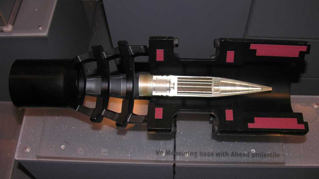
Enter AHEAD. It removes one uncertainty by measuring the velocity of each shell as it is fired then sets the timer after that. Two coils just past the end of the barrel can sense the projectile as it flies past. Its actual velocity is calculated from the time it took for the shell to go from one coil to the next. That information feeds into calculation for the desired timer countdown. (A little more sophisticated than distance divided by velocity due to aerodynamic drag and other factors.) Then a third coil wirelessly communicates with the shell (which, as a reminder, has already left the barrel) telling it when to scatter into tiny pieces.

When I read how the system worked, I thought “Hot damn, they can do that?” It felt like something from the future, even though the Wikipedia page for AHEAD said it’s been under development since 1993 and first fielded in 2011. The page also included this system cross-section image (CC BY-SA 4.0):

Cross section of the AHEAD 35mm ammunition system

It shows the three coils in red: two smaller velocity measurement coils followed by the larger inductive timer programming coil. Given the 35mm diameter of the shell, there seems to be roughly 100mm between the two velocity measurement coils. Wikipedia page for an AHEAD-capable weapon lists the muzzle velocity around 1050 meters per second, which calculates out to ~95 nanoseconds to cover the distance between those two coils. The length of the shell is a little over five times the diameter, and the inductive communication coil is somewhere towards the back so call it 5*35 = 175mm from tip of shell to inductive coil. The distance from second velocity coil to programming coil is roughly the diameter of the shell at 35mm. 175 + 35 = ~210mm distance. That implies in the neighborhood of 200 nanoseconds from the time the tip clears the second coil, to the time the two inductive communication coils line up. That 200ns is my rough guess as to the time window for the computer to perform its ballistic calculations and generate a timer value ready to transmit. That transmission itself must take place within some tens of nanoseconds, before the communication coils separate. That is not a lot of time, but evidently within the capability of modern electronics.

Here’s a YouTube video clip from a demonstration of an AHEAD-armed system firing against a swarm of eight drones. Since it’s a sales pitch, it’s no surprise all eight drones fell from the sky. But for me, the most telling camera viewpoint was towards the end, when it showed the intercept from a top-down camera view. We can see the airburst pattern to the left of the screen and the target swarm to the right. From this viewpoint, the top-down variation is due to aerodynamic and other effects and the left-right variation is due to shell-to-shell variation plus aerodynamic and other effects. To my eyes, the airbursts are in a circle, which I inferred to mean the system successfully compensated for shell-to-shell variation.

I’m not very knowledgeable about military hardware so I don’t know how this system measures up against other competitors for military budgets. But from a mechanical and electronics engineering perspective I was very impressed there is a way to set the fuze timer after the shell has been fired.

Mermaid.js for Diagrams in GitHub Markdown

This blog is a project diary, where I write down not just the final result, but all the distractions and outright wrong turns taken on the way. I write a much shorter summary (with less noise) for my projects in the README file of their associated GitHub repository. As much as I appreciate markdown, it’s just text and I have to fire up something else for drawings, diagrams, and illustrations. This becomes its own maintenance headache. It’d be nice to have tools built into GitHub markup for such things.

It turns out, I’m not the only one who thought so. I started by looking for a diagram tool to generate images I can link to my README files, preferably one that I might be able to embed into my own web app projects. From there I found Mermaid.js which looked very promising for future project integration. But that’s not the best part: Mermaid.js already have their fans, including people at GitHub. About a year ago, GitHub added support for Mermaid.js charts within their markdown variant, no graphic editor or separate image upload required.

I found more information on how to use this on GitHub documentation site, where I saw Mermaid is one of several supported tools. I have yet to need math formulas or geographic mapping in my markdown, but I have to come back to take a closer look into STL support.

As my first Mermaid test to dip my toes into this pool, I added a little diagram to illustrate the sequence of events in my AS7341 spectral color sensor visualization web app. I started with one of the sample diagrams on their live online editor and edited to convey my information. I then copied that Mermaid markup into my GitHub README.md file, and the diagram is now part of my project documentation there. Everything went through smoothly just as expected and no issues were encountered. Very nice! I’m glad I found this tool and I foresee adding a lot of Mermaid.js diagrams to my project README in the future. Even if I never end up integrating Mermaid.js into my own web app projects.

Running Angular Unit Tests (ng test) in VSCode Dev Container

I knew web development frameworks like Angular proclaim to offer a full package, but it’s always enlightening to find out what “full” does and doesn’t mean in each context. I had expected Angular to have its own layout engine and was mildly surprised (but also delighted) to learn the official recommendation is to use standard CSS, migrating off Angular-specific interim solutions.

Another area I knew Angular offered is a packaged set of testing tools: a combination of generic JavaScript testing tools and Angular-specific components already set up to work together as a part of Angular application boilerplate. We can kick off a test pass by running “ng test” and when I did so, I saw the following error message:

✔ Browser application bundle generation complete.
28 02 2023 09:17:22.259:WARN [karma]: No captured browser, open http://localhost:9876/
28 02 2023 09:17:22.271:INFO [karma-server]: Karma v6.4.1 server started at http://localhost:9876/
28 02 2023 09:17:22.272:INFO [launcher]: Launching browsers Chrome with concurrency unlimited
28 02 2023 09:17:22.277:INFO [launcher]: Starting browser Chrome
28 02 2023 09:17:22.279:ERROR [launcher]: No binary for Chrome browser on your platform.
  Please, set "CHROME_BIN" env variable.

Test runner Karma looked for Chrome browser and didn’t find it. This is because I’m running my Angular development environment inside a VSCode Dev Container, and this isolated environment couldn’t access the Chrome browser on my Windows 11 development desktop. It needs its own installation of Chrome browser and be configured to run in headless mode. (Which is itself undergoing an update but that’s not important right now.)

From these directions I installed Chrome in the container via command line.

sudo apt update
wget https://dl.google.com/linux/direct/google-chrome-stable_current_amd64.deb
sudo apt install ./google-chrome-stable_current_amd64.deb

Then Karma needs to be configured to run Chrome in headless mode. However, default Angular app boilerplate did not include karma.conf.js file which we need to edit. We need to tell Angular to create one:

ng generate config karma

Now we can edit the newly created file karma.conf.js following directions from here. Inside the call to config.set(), we need to define a custom launcher called “ChromeHeadless” then use that launcher in the browsers array. The results will look something like the following:

module.exports = function (config) {
  config.set({
    customLaunchers: {
      ChromeHeadless: {
        base: 'Chrome',
        flags: [
          '--no-sandbox',
          '--disable-gpu',
          '--headless',
          '--remote-debugging-port=9222'
        ]
      }
    },
    basePath: '',
    frameworks: ['jasmine', '@angular-devkit/build-angular'],
    plugins: [
@@ -33,7 +44,7 @@ module.exports = function (config) {
      ]
    },
    reporters: ['progress', 'kjhtml'],
    browsers: ['ChromeHeadless'],
    restartOnFileChange: true
  });
};

With these changes I can run “ng test” inside my dev container without any errors about running Chrome browser. Now I have an entirely different set of errors about object creation!


Appendix: Error Messages

Here are error messages I saw during this process, in order to help people to find these instructions by searching for the error message they saw.

Immediately after installing Chrome, running “ng test” will try launching Chrome but not in headless mode which will show these errors:

✔ Browser application bundle generation complete.
28 02 2023 17:50:43.190:WARN [karma]: No captured browser, open http://localhost:9876/
28 02 2023 17:50:43.202:INFO [karma-server]: Karma v6.4.1 server started at http://localhost:9876/
28 02 2023 17:50:43.202:INFO [launcher]: Launching browsers Chrome with concurrency unlimited
28 02 2023 17:50:43.205:INFO [launcher]: Starting browser Chrome
28 02 2023 17:50:43.271:ERROR [launcher]: Cannot start Chrome
        Failed to move to new namespace: PID namespaces supported, Network namespace supported, but failed: errno = Operation not permitted
[0228/175043.258978:ERROR:file_io_posix.cc(144)] open /sys/devices/system/cpu/cpu0/cpufreq/scaling_cur_freq: No such file or directory (2)
[0228/175043.259031:ERROR:file_io_posix.cc(144)] open /sys/devices/system/cpu/cpu0/cpufreq/scaling_max_freq: No such file or directory (2)

28 02 2023 17:50:43.271:ERROR [launcher]: Chrome stdout: 
28 02 2023 17:50:43.272:ERROR [launcher]: Chrome stderr: Failed to move to new namespace: PID namespaces supported, Network namespace supported, 
but failed: errno = Operation not permitted                                                                                                      [0228/175043.258978:ERROR:file_io_posix.cc(144)] open /sys/devices/system/cpu/cpu0/cpufreq/scaling_cur_freq: No such file or directory (2)
[0228/175043.259031:ERROR:file_io_posix.cc(144)] open /sys/devices/system/cpu/cpu0/cpufreq/scaling_max_freq: No such file or directory (2)

This has nothing to do with Karma because if I run Chrome directly from the command line, I see the same errors:

$ google-chrome
Failed to move to new namespace: PID namespaces supported, Network namespace supported, but failed: errno = Operation not permitted
[0228/175538.625191:ERROR:file_io_posix.cc(144)] open /sys/devices/system/cpu/cpu0/cpufreq/scaling_cur_freq: No such file or directory (2)
[0228/175538.625244:ERROR:file_io_posix.cc(144)] open /sys/devices/system/cpu/cpu0/cpufreq/scaling_max_freq: No such file or directory (2)
Trace/breakpoint trap

Running Chrome with just the “headless” flag is not enough.

$ google-chrome --headless
Failed to move to new namespace: PID namespaces supported, Network namespace supported, but failed: errno = Operation not permitted
[0228/175545.785551:ERROR:file_io_posix.cc(144)] open /sys/devices/system/cpu/cpu0/cpufreq/scaling_cur_freq: No such file or directory (2)
[0228/175545.785607:ERROR:file_io_posix.cc(144)] open /sys/devices/system/cpu/cpu0/cpufreq/scaling_max_freq: No such file or directory (2)
[0228/175545.787163:ERROR:directory_reader_posix.cc(42)] opendir /tmp/Crashpad/attachments/9114d20a-6c9e-451e-be47-353fb54f28be: No such file or 
directory (2)                                                                                                                                    Trace/breakpoint trap

We have to disable sandbox to get further, though that’s not the full solution yet either.

$ google-chrome --headless --no-sandbox
[0228/175551.357814:ERROR:bus.cc(399)] Failed to connect to the bus: Failed to connect to socket /run/dbus/system_bus_socket: No such file or dir
ectory                                                                                                                                           [0228/175551.361002:ERROR:bus.cc(399)] Failed to connect to the bus: Failed to connect to socket /run/dbus/system_bus_socket: No such file or dir
ectory                                                                                                                                           [0228/175551.361035:ERROR:bus.cc(399)] Failed to connect to the bus: Failed to connect to socket /run/dbus/system_bus_socket: No such file or dir
ectory                                                                                                                                           [0228/175551.365695:WARNING:bluez_dbus_manager.cc(247)] Floss manager not present, cannot set Floss enable/disable.

We also have to disable the GPU. Once done as per Karma configuration above, things will finally run inside a Dev Container.

Ubuntu Phased Package Update

I’m old enough to remember a time when it was a point of pride when a computer system can stay online for long periods of time (sometimes years) without crashing. It was regarded as one of the differentiations between desktop and server-class hardware to justify their significant price gap. Nowadays, a computer with years-long uptime is considered a liability: it certainly has not been updated with the latest security patches. Microsoft has a regular Patch Tuesday to roll out fixes, Apple rolls out their fixes on a less regular schedule, and Linux distributions are constantly releasing updates. For my computers running Ubuntu, running “sudo apt update” followed by “sudo apt upgrade” then “sudo reboot” is a regular maintenance task.

Recently (within the past few months) I started noticing a new behavior in my Ubuntu 22.04 installations: “sudo apt upgrade” no longer automatically installs all available updates, with a subset listed as “The following packages have been kept back”. I first saw this message before, and at that time it meant there were version conflicts somewhere in the system. This was a recurring headache with Nvidia drivers in past years, but that has been (mostly) resolved. Also, if this were caused by conflicts, explicitly upgrading the package would list its dependencies. But when I explicitly upgrade a kept-back package, it installed without further complaint. What’s going on?

$ sudo apt upgrade
Reading package lists... Done
Building dependency tree... Done
Reading state information... Done
Calculating upgrade... Done
Try Ubuntu Pro beta with a free personal subscription on up to 5 machines.
Learn more at https://ubuntu.com/pro
The following packages have been kept back:
  distro-info-data gnome-shell gnome-shell-common tzdata
The following packages will be upgraded:
  gir1.2-mutter-10 libmutter-10-0 libntfs-3g89 libpython3.10 libpython3.10-minimal libpython3.10-stdlib mutter-common ntfs-3g python3.10 python3.10-minimal
10 upgraded, 0 newly installed, 0 to remove and 4 not upgraded.
7 standard LTS security updates
Need to get 1,519 kB/9,444 kB of archives.
After this operation, 5,120 B disk space will be freed.
Do you want to continue? [Y/n]

A web search on “The following packages have been kept back” found lots of ways this message might come up. Some old problems going way back. But since this symptom may be caused by a large number of different causes, we can’t just blindly try every possible fix. We also need some way to validate the cause so we can apply the right fix. I found several different potential causes, and none of the validations applied, so I kept looking until I found this AskUbuntu thread suggesting I am seeing the effect of a phased rollout. In other words: this is not a bug, it is a feature!

When an update is rolled out, sometimes the developers find out too late a problem has escaped their testing. Rolling an update out to everyone at once also means such problems hit everyone at once. Phased update rollout tries to mitigate the damage of such problems: when an update is released, it is only rolled out to a subset of applicable systems. If those rollouts go well, the following phase will distribute the update to more systems, repeating until it is available to everyone. But sometimes somebody wants to skip the wait and install the new thing before their turn in a phased rollout, so they are allowed to “sudo apt upgrade” a package explicitly without error.

So back to the problem validation step: how would we know if a package is kept back due to phased rollout? We can pull up the “apt-cache policy” associated with a package and look for a “phased” percentage associated with the latest version. If so, that means the update is in the middle of a phased rollout. If the updated package is important to us, we can explicitly upgrade now. But if it is not, we can just wait for the phases to include us and be installed in a future “sudo apt upgrade” run.

$ apt-cache policy tzdata
tzdata:
  Installed: 2022e-0ubuntu0.22.04.0
  Candidate: 2022f-0ubuntu0.22.04.0
  Version table:
     2022f-0ubuntu0.22.04.0 500 (phased 10%)
        500 http://us.archive.ubuntu.com/ubuntu jammy-updates/main amd64 Packages
        500 http://us.archive.ubuntu.com/ubuntu jammy-updates/main i386 Packages
        500 http://security.ubuntu.com/ubuntu jammy-security/main amd64 Packages
        500 http://security.ubuntu.com/ubuntu jammy-security/main i386 Packages
 *** 2022e-0ubuntu0.22.04.0 100
        100 /var/lib/dpkg/status
     2022a-0ubuntu1 500
        500 http://us.archive.ubuntu.com/ubuntu jammy/main amd64 Packages
        500 http://us.archive.ubuntu.com/ubuntu jammy/main i386 Packages

Digital Ink and the Far Side Afterlife

A few weeks ago I picked up a graphical drawing display to play with. I am confident in my skills with software and knowledge of electronics, but I was also fully aware none of that would help me actually draw. That will take dedication and practice, which I am still working on. Very different from myself are those who come at this from the other side: they have the artistic skills, but maybe not in the context of digital art. Earlier I mentioned The Line King documentary (*) showed Al Hirschfeld playing with a digital tablet climbing the rather steep learning curve to transfer his decades of art skills to digital tools. I just learned of another example: Gary Larson.

Like Al Hirschfeld, Gar Larson is an artist I admired but in an entirely different context. Larson is the author of The Far Side, a comic that was published in newspapers via syndication. If you don’t already know The Far Side it can be hard to explain, but words like strange, weird, bizarre, and surreal would be appropriate. I’ve bought several Far Side compilations, my favorite being The PreHistory of The Far Side (*) which included behind-the-scenes stories from Gary Larson to go with selected work.

With that background, I was obviously delighted to find that the official Far Side website has a “New Stuff” section, headlined by a story from Larson about new digital tools. After retirement, Larson would still drag out his old tools every year to draw a Christmas card. A routine that has apparently been an ordeal dealing with dried ink on infrequently used pen. One year instead of struggling with cleaning a clogged pen, Larson bought a digital drawing tablet and rediscovered the joy of artistic creation. I loved hearing that story and even though only a few comics have been published under that “New Stuff” section, I’m very happy that an artist I admired has found joy in art again.

As for myself, I’m having fun with my graphical drawing display. The novelty has not yet worn off, but neither have I produced any masterpieces. The future of my path is still unknown.


(*) Disclosure: As an Amazon Associate I earn from qualifying purchases.

Non-Photorealistic Rendering

Artists explore where the mainstream is not. That’s been true for as long as we’ve had artists exploring. Early art worked to develop techniques that capture reality the way we see them with our eyes. And once tools and techniques were perfected for realistic renditions, artists like Picasso and Dali went off to explore art that has no ambition to be realistic.

This evergreen cycle is happening in computer graphics. Early computer graphics were primitive cartoony blocks but eventually evolved into realistic-looking visuals. We’re now to the point where computer generated visual effects can be seamlessly integrated into camera footage and the audience couldn’t tell what was real and what was not. But now that every CGI film looks photorealistic, how does one stand out? The answer is to move away from photorealism and develop novel non-photorealistic rendering techniques.

I saw this in Spider-Man: Into the Spider-Verse, and again in The Mitchells vs. the Machines. I was not surprised that some of the same people were behind both films. Each of these films had their own look, distinct from each other and far from other computer animated films. I remember thinking “this might be interesting to learn more about” and put it in the back of my mind. So when this clip came up as recommended by YouTube, I had to click play and watch it. I’m glad I did.

From this video I learned that the Spider-Verse people weren’t even sure if audience would accept or reject their non-conformity to standards set by computer animation pioneer Pixar. That is, until the first teaser trailer was released and received positively to boost their confidence in their work.

I also learned that they were created via rendering pipelines that have additional stylization passes tacked on to the end of existing photorealistic rendering. However, I don’t know if that’s necessarily a requirement for future exploration in this field, it seems like there’d be room for exploring pipelines that skip some of the photorealistic aspects, but I don’t really know enough to make educated guesses. This is a complex melding of technology and art. It takes some unique talent and experience to pull off. Which is why it made sense (in hindsight) that entire companies exist to consult for non-realistic rendering, with Lollipop Shaders the representative in this video.

As I’m no aspiring filmmaker, I doubt I’ll get anywhere near there, but what about video game engines like Unity 3D? I was curious if anyone has explored applying similar techniques to the Unity rendering pipeline. I looked on Unity’s Asset Store under the category of VFX / Shaders / Fullscreen & Camera Effects. And indeed, there were several offerings. In the vein of Spider-Verse I found a comic book shader. Painterly is more like Mitchells but not in the same way. Shader programmer flockaroo has several art styles on offer, from “notebook drawings” to “Van Gogh”. If I’m ever interested in doing something in Unity and want to avoid the look of default shaders, I have options to buy versus developing my own.

Fan Blade Counter Fail: IR Receiver is not Simple Phototransistor

After a successful Lissajous experiment with my new oscilloscope, I proceeded to another idea to explore multichannel capability: a fan blade counter. When I looked at the tachometer wire on a computer cooling fan, I could see a square wave on a single-channel oscilloscope. But I couldn’t verify how that corresponded to actual RPM, because I couldn’t measure the latter. I thought I could set up an optical interrupter and use the oscilloscope to see individual fan blades interrupt the beam as they spun. Plotting the tachometer wire on one oscilloscope channel and the interrupter on another would show how they relate to each other. However, my first implementation of this idea was a failure.

I needed a light source, plus something sensitive to that particular light, and they need to be fast. I have some light-sensitive resistors on hand, but their reaction times are too slow to count fan blades. A fan could spin up to a few thousand RPM and a fan has multiple blades. So, I need a sensor that could handle signals in the tens of kilohertz and up. Looking through my stock of hardware, I found a box of consumer infrared remote-control emitter and receiver modules (*) from my brief exploration into infrared. Since consumer IR usually modulate their signals with a carrier frequency in the ballpark of 38kHz, these should be fast enough. But trying to use them to count fan blades was a failure because I misunderstood how the receiver worked.

I set up an emitter LED to be always-on and pointed it at a receiver. I set up the receiver with power, ground, and its signal wire connected to the oscilloscope. I expected the signal wire to be at one voltage level when it sees the emitter, and at another voltage level when I stick an old credit card between them. Its actual behavior was different. The signal was high when it saw the emitter, and when I blocked the light, the signal is… still high. Maybe it’s only setup to work at 38kHz? I connected the emitter LED to a microcontroller to pulse it at 38kHz. With that setup, I can see a tiny bit of activity with my block/unblock experiment.

Immediately after I unblocked the light, I see a few brief pulses of low signal before it resumed staying high. If I gradually unblocked the light, these low signals stayed longer. Even stranger, if I do the opposite thing and gradually blocked the light, I also get longer pulses of low signal.

Hypothesis: this IR receiver isn’t a simple photoresistor changing signal high or low depending on whether it sees a beam or not. There’s a circuit inside looking for a change in intensity and the signal wire only goes low when it sees behavior that fits some criteria I don’t understand. That information is likely to be found in the datasheet for this component, but such luxuries are absent when we buy components off random Amazon lowest-bidder vendors instead of a reputable source like Digi-Key. Armed with microcontroller and oscilloscope, I could probably figure out the criteria for signal low. But I chose not to do that right now because, no matter the result, it won’t be useful for a fan blade counter. I prefer to stay focused on my original goal, and I have a different idea to try.


(*) Disclosure: As an Amazon Associate I earn from qualifying purchases.

Learned About Home Assistant From ESPHome Via WLED

I thought Adafruit’s IO platform was a great service for building network-connected devices. If my current project had been something I wanted to be internet-accessible with responses built on immediate data, then that would be a great choice. However, my current intent is for something locally at home and I wanted the option to query and analyze long term data, so I started looking at Home Assistant instead.

I found out about Home Assistant in a roundabout way. The path started with a tweet from GeekMomProjects:

A cursory look at WLED’s home page told me it is a project superficially similar to Ben Hencke’s Pixelblaze: an ESP8266/ESP32-based platform for building network-connected projects that light up individually addressable LED arrays. The main difference I saw was of network control. A Pixelblaze is well suited for standalone execution, and the network interface is primarily to expose its web-based UI for programming effects. There are ways to control a Pixelblaze over the network, but they are more advanced scenarios. In contrast, WLED’s own interface for standalone effects are dominated by less sophisticated lighting schemes. For anything more sophisticated, WLED has an API for control over the network from other devices.

The Pixelblaze sensor board is a good illustration of this difference: it is consistent with Pixelblaze design to run code that reacts to its environment with the aid of a sensor board. There’s no sensor board peripheral for a WLED: if I want to build a sensor-reactive LED project using WLED, I would build something else with a sensor, and send commands over the network to control WLED lights.

So what would these other network nodes look like? Following some links led me to the ESPHome project. This is a platform for building small network-connected devices using ESP8266/ESP32 as its network gateway, with a library full of templates we can pick up and use. It looks like WLED is an advanced and specialized relative of ESPHome nodes like their adaptation of the FastLED library. I didn’t dig deeper to find exactly how closely related they are. What’s more interesting to me right now is that a lot of other popular electronics devices are available in the ESPHome template library, including the INA219 power monitor I’ve got on my workbench. All ready to go, no coding on my part required.

Using an inexpensive ESP as a small sensor input or output node, and offload processing logic somewhere else? This can work really well for my project depending on that “somewhere else.” If we’re talking about some cloud service, then we’re no better off than Adafruit IO. So I was happy to learn ESPHome is tailored to work with Home Assistant, an automation platform I could run locally.

Unity DOTS = Data Oriented Technology Stack

Looking over resources for Unity ML-Agents toolkit for reinforcement learning AI algorithms, I’ve come across multiple discussion threads about how it has difficulties scaling up to take advantage of modern multicore computers. This is not just a ML-Agents challenge, this is a Unity-wide challenge. Arguably even a software development industry-wide challenge. When CPUs stopped getting faster clock rates and started gaining more cores, games have had problem taking advantage of them. Historically while a game engine is running, there is one CPU core running at max. The remaining cores may help out with a few auxiliary tasks but mostly sit idle. This is why gamers have been focused on single-core performance in CPU benchmarks.

Having multiple CPUs running in parallel isn’t new, nor are the challenges of leveraging that power in full. From established software toolkits to leading edge theoretical research papers, there are many different approaches out there. Reading these Unity forum posts, I learned that Unity is working on a big revamp under the umbrella of DOTS: Data-Oriented Technology Stack.

I came across the DOTS acronym several times without understanding what it was. But after it came up in the context of better physics simulation and a request for ML-Agents to adopt DOTS, I knew I couldn’t ignore the acronym anymore.

I don’t know a whole lot yet, but I’ve got the distinct impression that working under DOTS will require a mental shift in programming. There were multiple references to Unity developers saying it took some time for the concepts to “click”, so I expect some head-scratching ahead. Here are some resources I plan to use to get oriented:

DOTS is Unity’s implementation of Data-oriented Design, a more generalized set of concepts that helps write code that will run well on modern machines with many cores and multiple levels of memory caches. An online eBook for Data-oriented Design is available, which might be good to read so I can see if I want to adopt these concepts in my own programming projects outside of Unity.

And just to bring this full circle: it looks like the ML-Agents team has already started DOTS work as well. However it’s not clear to me how DOTS will (or will not) help with the current gating performance factor: Unity environment’s communication with PyTorch (formerly TensorFlow) running in a Python environment.

Today I Learned: MuJoCo Is Now Free To Use

I’ve contemplated going through OpenAI’s guide Spinning Up in Deep RL. It’s one of many resources OpenAI made available, and builds upon the OpenAI Gym system of environments for training deep reinforcement learning agents. They range from very simple text-based environments, to 2D Atari games, to full 3D environments built with MuJoCo. Whose documentation explained that name is a shorthand for the type of interactions it simulates: “Multi Joint Dynamics with Contact”

I’ve seen MuJoCo mentioned in various research contexts, and I’ve inferred it is a better physics simulation than something that we would find in, say, a game engine like Unity. No simulation engine is perfect, they each make different tradeoffs, and it sounds like AI researchers (or at least those at OpenAI) believe MuJoCo to be the best one to use for training deep reinforcement learning agents with the best chance of being applicable to the real world.

The problem is that, when I looked at OpenAI Gym the first time, MuJoCo was expensive. This time around, I visited the MuJoCo page hoping that they’ve launched a more affordable tier of licensing, and there I got the news: sometime in the past two years (I didn’t see a date stamp) DeepMind has acquired MuJoCo and intend to release it as free open source software.

DeepMind was itself acquired by Google and, when the collection of companies were reorganized, it became one of several companies under the parent company Alphabet. At a practical level, it meant DeepMind had indirect access to Google money for buying things like MuJoCo. There’s lots of flowery wordsmithing about how opening MuJoCo will advance research, what I care about is the fact that everyone (including myself) can now use MuJoCo without worrying about the licensing fees it previously required. This is a great thing.

At the moment MuJoCo is only available as compiled binaries, which is fine enough by me. Eventually it is promised to be fully open-sourced at a GitHub repository set up for the purpose. The README of the repository made one thing very clear:

This is not an officially supported Google product.

I interpret this to mean I’ll be on my own to figure things out without Google technical support. Is that a bad thing? I won’t know until I dive in and find out.

Today I Learned About Flippa

I received a very polite message from Jordan representing Flippa who asked if I’d be interested in selling this site https://newscrewdriver.com. Thank you for the low-pressure message, Jordan, but I’m keeping it for the foreseeable future.

When I received the message, I didn’t know what Flippa was so I went and took a cursory look. At the surface it seems fairly straightforward: a marketplace to buy and sell online properties. Anything from just a domain to e-commerce sites with established operational history. The latter made sense to me because a valuation can be calculated from an established revenue stream. The rest I’m less confident about. Such as domain names, whose valuation are a speculation on how it might be monetized.

But there’s a wide spectrum between those two endpoints of “established business” and “wild speculation”. I saw several sites for sale set up by people that started with an idea, set up a site to maximize search engine traffic over a few months, then sell the site based on that traffic alone. Prices range wildly. At time of my browsing, auction for one such site is about to close at $25. But they seem to range up to several thousand dollars, so I guess it’s possible to make a living doing this if your ideas (and SEO skills) are good.

Mine are not! But money was not the intent when I set up this site anyway. It is a project diary of stuff I find interesting to learn about and work on. I made it public because there’s no particular need for privacy and some of this information may be useful to others. (Most of it are not useful to anybody, but that’s fine too.) So it’s all here in written text format for easy searching. Both by web search engines, and with browser “find text” once they arrive.

I haven’t even tried to put ads on this page. (Side note: I’m thankful modern page ads have evolved past the “Punch the Monkey” phase.) I also understand if my intent is to generate advertising revenue, I should be doing this work in video format on YouTube. But video files are hard to search and skim through. Defeating the purpose of making this project diary easily available for others to reference. I had set up a New Screwdriver YouTube channel and made a few videos, but even my low effort videos took more far more work than typing some words. For all these reasons I decided to primarily stay with the written word and reserve video for specific topics best shown in video format.

The only thing I’ve done to try monetizing this site is joining the Amazon Associates program, where my links to stuff I’ve bought on Amazon can earn me a tiny bit of commission. The affiliate links don’t add to the cost to buy those things. And even though I’ve had to add a line of disclosure text, that’s still less jarring of an interruption than page ads. So far Amazon commissions have been just about enough to cover the direct costs of running this site (annual domain registration fee and site hosting fee) and I’m content to leave it at that.

But hey, that is still revenue associated with this site! Browsing Flippa for similar sites based on age, traffic, and revenue, my impression is that market rate is around $100. (Low confidence with huge error margins.) Every person has their price, but that’s several orders of magnitude too low to motivate me to abandon my project diary.

Shrug. New Screwdriver sails on.

TIL Some Video Equipment Support Both PAL and NTSC

Once I sorted out memory usage of my ESP_8_BIT_composite Arduino library, I had just one known issue left on the list. In fact, the very first one I filed: I don’t know if PAL video format is properly supported. When I pulled this color video signal generation code from the original ESP_8_BIT project, I worked to keep all the PAL support code intact. But I live in NTSC territory, how am I going to test PAL support?

This is where writing everything on GitHub paid off. Reading my predicament, [bootrino] passed along a tip that some video equipment sold in NTSC geographic regions also support PAL video, possibly as a menu option. I poked around the menu of the tube TV I had been using to develop my library, but didn’t see anything promising. For the sake of experimentation I switched my sketch into PAL mode just to see what happens. What I saw was a lot of noise with a bare ghost of the expected output, as my TV struggled to interpret the signal in a format it could almost but not quite understand.

I knew the old Sony KP-53S35 RPTV I helped disassemble is not one of these bilingual devices. When its signal processing board was taken apart, there was an interface card to host a NTSC decoder chip. Strongly implying that support for PAL required a different interface card. It also implies newer video equipment have a better chance of having multi-format support, as they would have been built in an age when manufacturing a single worldwide device is cheaper than manufacturing separate region-specific hardware. I dug into my hardware hoard looking for a relatively young piece of video hardware. Success came in the shape of a DLP video projector, the BenQ MS616ST.

I originally bought this projector as part of a PC-based retro arcade console with a few work colleagues, but that didn’t happen for reasons not important right now. What’s important is that I bought it for its VGA and HDMI computer interface ports so I didn’t know if it had composite video input until I pulled it out to examine its rear input panel. Not only does this video projector support composite video in both NTSC and PAL formats, it also had an information screen where it indicates whether NTSC or PAL format is active. This is important, because seeing the expected picture isn’t proof by itself. I needed the information screen to verify my library’s PAL mode was not accidentally sending a valid NTSC signal.

Further proof that I am verifying a different code path was that I saw a visual artifact at the bottom of the screen absent from NTSC mode. It looks like I inherited a PAL bug from ESP_8_BIT, where rossumur was working on some optimizations for this area but left it in a broken state. This artifact would have easily gone unnoticed on a tube TV as they tend to crop off the edges with overscan. However this projector does not perform overscan so everything is visible. Thankfully the bug is easy to fix by removing an errant if() statement that caused PAL blanking lines to be, well, not blank.

Thanks to this video projector fluent in both NTSC and PAL, I can now confidently state that my ESP_8_BIT_composite library supports both video formats. This closes the final known issue, which frees me to go out and find more problems!

[Code for this project is publicly available on GitHub]

Jumper Wire Headaches? Try Cardboard!

My quick ESP32 motor control project was primarily to practice software development for FreeRTOS basics, but to make it actually do something interesting I had to assemble associated hardware components. The ESP32 development kit was mounted on a breadboard, to which I’ve connected a lot of jumper wires. Several went to a Segger J-Link so I had the option of JTAG debugging. A few other pins went to potentiometers of a joystick so I could read its position, and finally a set of jumper wires to connect ESP32 output signals to a L298N motor control module. The L298N itself was connected to DC motors of a pair of TT gearboxes and a battery connector for direct power.

This arrangement resulted in an annoying number of jumper wires connecting these six separate physical components. I started doing this work on my workbench and the first two or three components were fine. But once I got up to six, things to start going wrong. While working on one part, I would inadvertently bump another part which tugs on their jumper wires, occasionally pulling them out of the breadboard. At least those pulled completely free were clearly visible, the annoying cases are wires only pulled partially free causing intermittent connections. Those were a huge pain to debug and of course I would waste time thinking it was a bug in my code when it wasn’t.

I briefly entertained the idea of designing something in CAD and 3D-print it to keep all of these components together as one assembly, but I rejected that as sheer overkill. Far too complex for what’s merely a practice project. All I needed was a physical substrate to temporarily mount these things, there must be something faster and easier than 3D printing. The answer: cardboard!

I pulled a box out of my cardboard recycle bin and cut out a sufficiently large flat panel using my Canary cutter. The joystick, L298N, and TT gearboxes had mounting holes so a few quick stabs to the cardboard gave me holes to fasten them with twist ties. (I had originally thought to use zip ties, but twist ties are more easily reused.) The J-Link and breadboard did not have convenient mounting holes, but the breadboard came backed with double-sided adhesive so I exposed a portion for sticking to the cardboard. And finally, the J-Link was held down with painter’s masking tape.

All this took less than ten minutes, far faster than designing and 3D printing something. After securing all components of this project into a single cardboard-backed physical unit, I no longer had intermittent connection problems with jumper wires accidentally pulled loose. Mounting them on a sheet of cardboard was time well spent, and its easily modified nature makes it easy for me to replace the L298 motor driver IC used in this prototype.

I Started Learning Jamstack Without Realizing It

My recent forays into learning about static-site generators, and the earlier foray into Angular framework for single-page applications, had a clearly observable influence on my web search results. Especially visible are changes in the “relevant to your interests” sidebars. “Jamstack” specifically started popping up more and more frequently as a suggestion.

Web frameworks have been evolving very rapidly. This is both a blessing when bug fixes and new features are added at a breakneck pace, and a curse because knowledge is quickly outdated. There are so many web stacks I can’t even begin to track of what’s what. With Hugo and Angular on my “devise a project for practice” list I had no interest in adding yet another concept to my to-do list.

But with the increasing frequency of Jamstack being pushed on my search results list, it was a matter of time before an unintentional click took me to Jamstack.org. I read the title claim in the time it took for me to move my mouse cursor towards the “Back” button on my browser.

The modern way to build [websites & apps] that delivers better performance

Yes, of course, they would all say that. No framework would advertise they are the old way, or that they deliver worse performance. So none of the claim is the least bit interesting, but before I clicked “Back” I noticed something else: the list of logos scrolling by included Angular, Hugo, and Netlify. All things that I have indeed recently looked at. What’s going on?

So instead of clicking “Back”, I continued reading and learned proponents of Jamstack are not promoting a specific software tool like I had ignorantly assumed. They are actually proponents of an approach to building web applications. JAM stands for (J)avaScript, web (A)PIs, and (M)arkup. Tools like Hugo and Angular (and others on that scrolling list) are all under that umbrella. An application developer might have to choose between Angular and its peers like React and Vue, but no matter the decision, the result is still JAM.

Thanks to my click mistake, I now know I’ve started my journey down the path of Jamstack philosophy without even realizing it. Now I have another keyword I can use in my future queries.

Randomized Dungeon Crawling Levels for Robots

I’ve spent more time than I should have on Diablo III, a video game where our hero adventures through endless series of challenges. Each level in the game has a randomly generated layout so it’s not possible to memorize where the most rewarding monsters live or where the best treasures are hidden. This keeps the game interesting because every level is an exploration in an environment I’ve never seen before and will never see its exact duplicate again.

This is what came to my mind when I learned of WorldForge, a new feature of AWS RoboMaker. For those who don’t know: RoboMaker is an AWS offering built around ROS (Robot Operating System) that lets robot builders leverage the advantages of AWS. One example most closely relevant to WorldForge is the ability to run multiple virtual robot simulations in parallel across a large number of AWS machines. It’ll cost money, of course, but less than buying a large number of actual physical computers to run those simulations.

But running a lot of simulations isn’t very useful whey they are all running the same robot through the same test environment, and this is where WorldForge comes in. It’s a tool that accepts a set of parameters, then generate a set of simulation worlds that randomly place or replace features according to those given parameters. Then virtual robots can be set loose to do their thing across AWS machines running in parallel. Consistent successful completion across different environments builds confidence our robot logic is properly generalized and not just memorizing where the best treasures are buried. So basically, a randomized dungeon crawler adventure for virtual robots.

WorldForge launched with ability to generate randomized residential environments, useful for testing robots intended for home use. To broaden the appeal of WorldForge, other types of environments are coming in the future. So robots won’t get bored with the residential tileset, they’ll also get industrial and business tilesets and more to come.

I hope they appreciate the effort to keep their games interesting.