Orthogonal Fans with Pixelblaze 3D Mapping

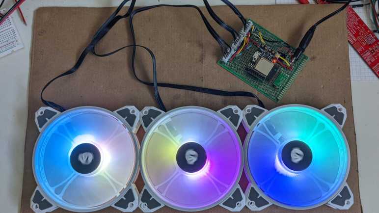
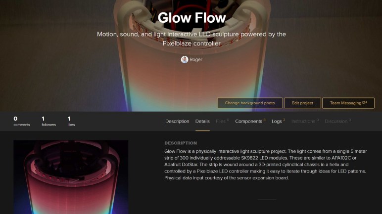
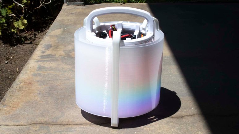
I have built a control board for a trio of affordable PC case fans, replacing their bundled control hub of this Asiahorse Magic-i 120 V2 system. With my board I can control individual RGB LED inside these fans with help of a Pixelblaze LED controller. My initial tests used simple built-in linear patterns, but I wanted to use patterns that take advantage of 3D coordinate mapping. This is my favorite part of Pixelblaze and a core part of my Glow Flow project.

To get a 3D structure out of three fans, I did the easiest and most expedient thing: orient them orthogonal to each other with a few twist-ties. Now every fan motor axis lines up with one of three axes in 3D space. I have a Pixelblaze 3D coordinate test program already in hand, the RGB-XYZ 3D Sweep program I created during Glow Flow. All I had to do was create a 3D coordinate map in my Pixelblaze to describe LED layout in three-dimensional space.

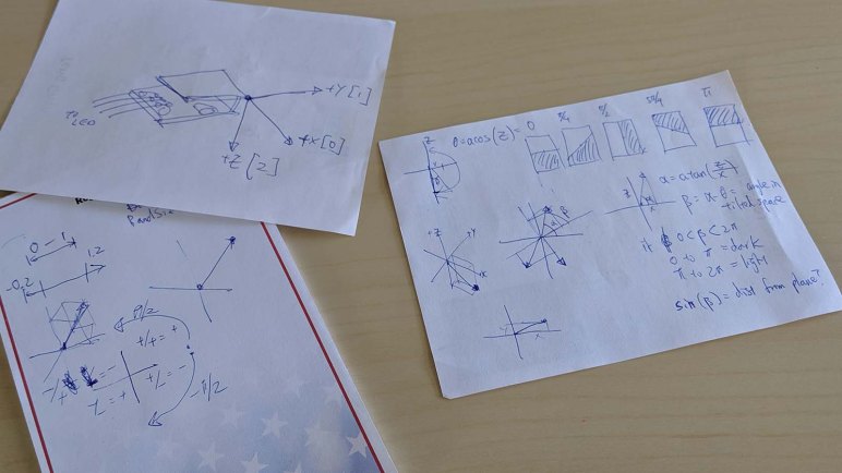
I opened up the Pixelblaze mapping editor and… immediately got stuck. Where, exactly, should I map these LEDs? Physically, they are surface mounted on the central hub. However, their light diffused by translucent fan blade plastic, no longer fixed to a single location but distributed across entire fan diameter. Should I map the LEDs where they are physically? Or fan blade outer perimeter? Or somewhere in between? There really isn’t one single location for resulting output of a single LED.

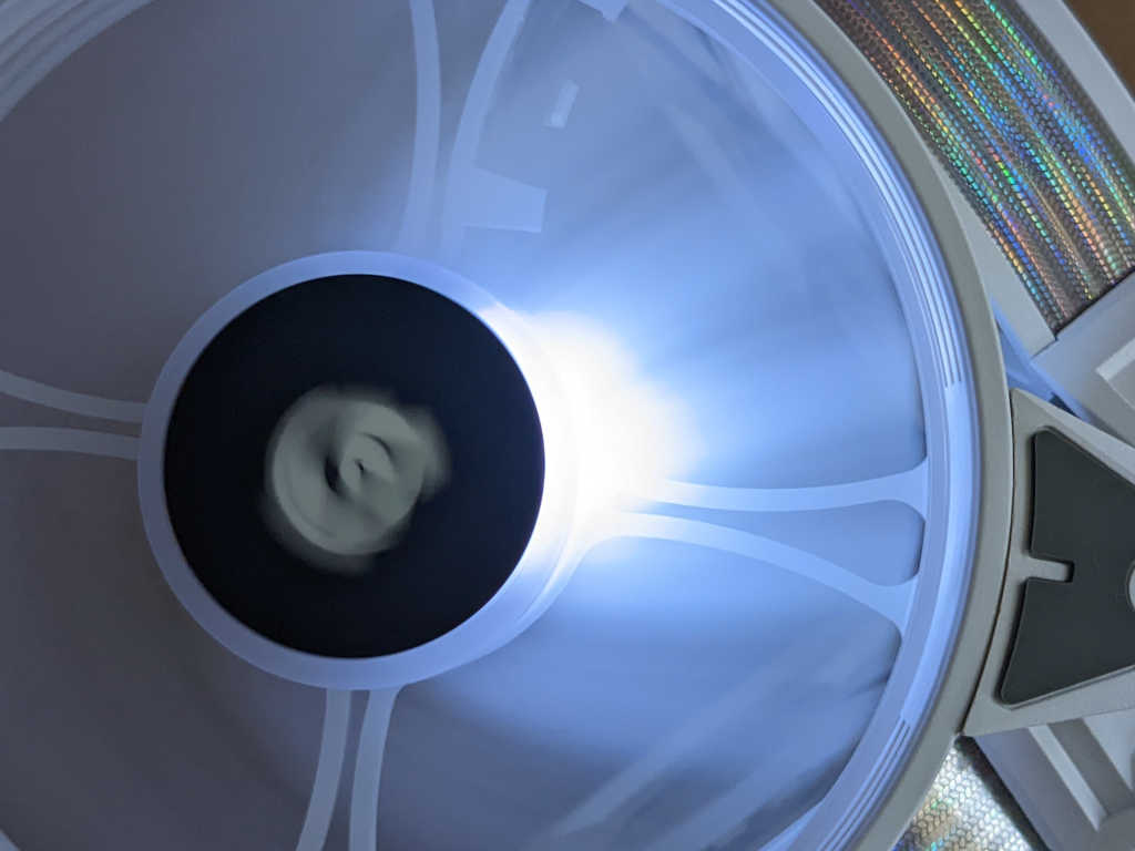
I decided to experiment by writing my mapping code so a single variable controls how far from the center each location is. When pixelRadius is zero, everything is at the center and not very interesting. When set to 0.5, everything is mapped to the perimeter. I adjusted this value until the pattern “looked right” and that ended up at 0.4. I’m not satisfied with the empirical nature of this value, but I haven’t figured out a better way to account for diffusion.

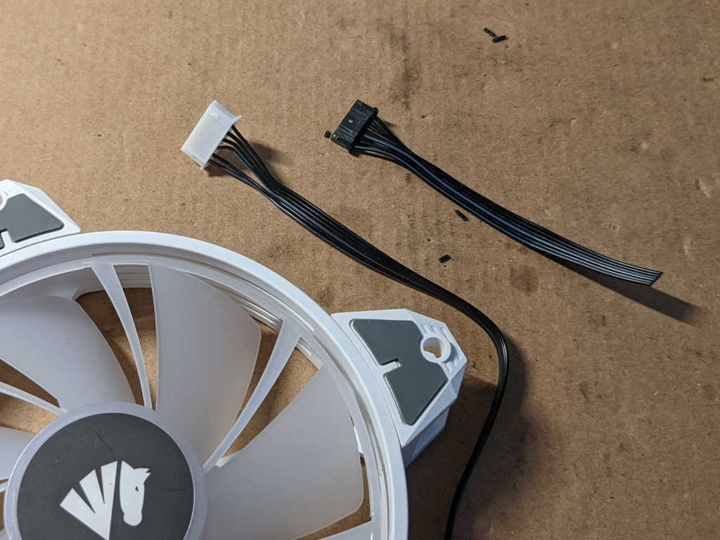
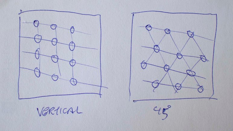
Another problem with these LEDs is that they weren’t placed with precise coordinates in mind. I think LEDs were laid out on the circuit board relative to wiring bundle location, which is slightly offset from one of the four mounting arms. As a result, the LEDs aren’t aligned to any reference point on the exterior. To use an analog clock face as example, these LEDs are evenly placed but slightly offset from the hour numbers. Instead of lined up at 12, 1, 2, 3. They are at 12:10, 1:10, 2:10, etc.

These fans are physically squares with side lengths of 120mm. They can be installed in one of four orientations that are 90 degrees from each other and be mechanically fine. I usually choose my orientation based on whichever makes the wiring most convenient. But whatever the motivation, my 3D coordinate map would have to compensate for the resulting rotation.

The answer for both of the above rotation compensation concerns is an array fanRotationCorrection. One value for each fan, a sum of physical and LED offset rotations (in radians) added into coordinate map angle calculation for that fan.

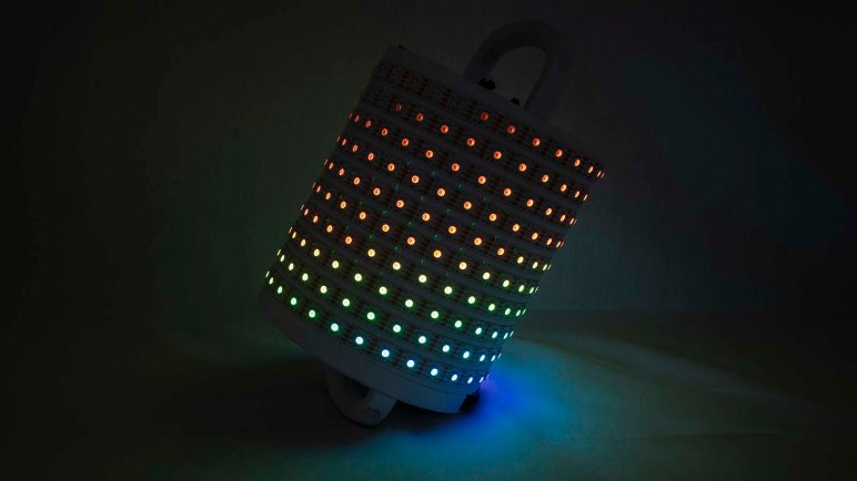
Here is the result of my 3D pixel map running my RGB-XYZ sweep test program:

Here is my Pixelblaze Pixel Mapper code. [UPDATE: I later noticed that I got my Z-axis backwards. Be aware that both the video embedded in the tweet and this pixel mapper code are known to be flawed. At least they’re consistent with each other!]

function(pixelCount) {
  pixelPerFan = 12;
  pixelRadius = 0.4;
  fanRotationCorrection = [0.65, 0.65, 0.65];

  var map = [];
  for (i = 0; i < pixelCount; i++) {
    var ledNumber = i % pixelPerFan;
    var ledRadians = ((ledNumber/pixelPerFan) * Math.PI * 2);

    if (i < pixelPerFan) {
      ledRadians += Math.PI*fanRotationCorrection[0]
      map.push([0, 0.5 + Math.cos(ledRadians)*pixelRadius, 0.5 - Math.sin(ledRadians)*pixelRadius]);
    } else if (i < pixelPerFan*2) {
      ledRadians += Math.PI*fanRotationCorrection[1]
      map.push([0.5 - Math.cos(ledRadians)*pixelRadius, 0, 0.5 - Math.sin(ledRadians)*pixelRadius]);
    } else if (i < pixelPerFan*3) {
      ledRadians += Math.PI*fanRotationCorrection[2]
      map.push([0.5 - Math.cos(ledRadians)*pixelRadius, 0.5 + Math.sin(ledRadians)*pixelRadius, 0]);
    } else {
      // Unexpected pixels are placed at origin
      map.push(0,0,0);
    }
  }
  return map;
}

My Asiahorse investigation results were also posted to Pixelblaze forums. And now that I have full and complete control over these fans, I no longer need the hub that came in the box.

Control Board for Asiahorse 120mm Fans with RGB LED

I have a trio of PC cooling fans with embedded addressable RGB LED. They were designed to plug into a control hub that came in the bundle, but that hub had only a limited set of patterns and appeared to send the same signal to all fans. In order to run my own light show and control each fan individually, I determined the fan pinout and will now build my own control board for these fans.

The first problem was wiring. These fans came with a JST-PH style plug with 2.0mm pitch. (Distance between pins.) My perforated prototype circuit boards (and most connectors and components on hand) have a pitch of 0.1″ (~2.54mm) and would not fit. To work around this problem today, I cut off the factory connector and crimped on a replacement. These are JST-XH clones(*) with 0.1″ pitch. In the future, I might consider buying some perforated prototype boards with 2.0mm pitch (*) but that would have the problem of using components with 0.1″ pitch. The real solution is to make my own circuit boards that can accommodate whatever pitch I need, but that’s beyond my reach at the moment.

To generate individual control signals for these fans, I will be using the very awesome Pixelblaze controller. For power I will be using one of my salvaged 12V DC power bricks. It is rated for up to 1.5A which should be sufficient for a trio of fans and 12*3 = 36 LEDs. The barrel jack has a 5.5mm outer diameter and 2.1mm inner diameter, so I soldered a matching power jack (*) to the board. This will deliver power for the fans, with a decoupling capacitor to smooth things out. A buck converter (*) with convenient 5V preset feeds from that 12V rail to deliver 5V for Pixelblaze and LEDs.

I soldered some 2N2222A transistors for potential control of fan speed, but for this first iteration they’re pulled high so the fans spin all the time. It would have been easier to solder fan motor low wire directly to ground, but I have ambition of fan control in a future update.

The LEDs are connected in serial across all three fans. Pixelblaze data is connected to “data in” of the first fan, whose “data out” is connected to “data in” of the second fan, and onwards to the third fan. Configured for 12*3 = 36 WS2812-style LEDs, the Pixelblaze has individual control of every LED with a single data line. And for the first time, these three fans show patterns different from each other. With this new power I can make things even more interesting.


(*) Disclosure: As an Amazon Associate I earn from qualifying purchases.

Documenting Glow Flow Online

My Pixelblaze (and its sensor board) demonstration project Glow Flow is now complete. Well, maybe not “complete” but I’ve decided to stop here instead of exploring other ideas to continue evolving project. For now I’ll keep Glow Flow as-is, but before I shift attention to other projects, I should finish documenting this one before I forget everything.

First thing to do is to create a Hackaday.io project page, with links to all the other resources. Then I gathered all the video I’ve shot through the project and edited them all together into a YouTube video. (Embedded below.) I personally prefer to read about projects, but I acknowledge that some prefer video and I want them to enjoy Glow Flow as well.

The Github repository where I had been tracking my Pixelblaze pattern code revisions also got an updated README.md. So anyone who encounters the project on Github will have links to all the other resources I’ve put online. And like every other file I’ve created on the free tier of Onshape, Glow Flow CAD data is publicly available too.

As an experiment I put Glow Flow on Hackster.io as well. It’s not terribly different from a Hackaday.io project page, with one notable exception: I’m expected to upload a schematic for a project before publishing it. This meant I had to fire up KiCad and re-learn its schematic editor to create a rudimentary schematic detailing how Glow Flow electronics components are connected. I didn’t think it was a very sophisticated circuit, but my judgement is not to be trusted as everything is still fresh in my mind. Chances are good I’ll forget details in the future and appreciate the schematic is available. I’ve also uploaded the schematic to the Github repo so it is saved in at least two different places.

This should be enough information for someone (including future me) to understand and build another Glow Flow if they so desire.

Glow Flow Project Complete

With an upgraded power system, Glow Flow can now run continuously at full brightness. This completes Glow Flow as a self-contained portable demonstration of Pixelblaze LED controller. I plan to leave it in this configuration for the foreseeable future, but the flexibility of Pixelblaze and the 3D-printed snap-together construction means it’d be easy to reuse the core components for another project in the future. The Pixelblaze is in no shortage of storage space for other patterns, and the LED strip wound around a cylindrical core can easily accept a different external “sleeve” tailored to a different design.

People have suggested some other visual patterns, some would work better with different LED diffuser exterior:

  • Illusion of a lantern, complete with a flickering flame inside.
  • Illusion of a fish tank, with colorful fishes swimming inside.
  • Glowing lava, matching my original plan.
  • Animated Jack-o-Lantern for Halloween.
  • Glowing green like a bucket of radioactive slime.
  • Glowing purple/pink like the Energon Cubes in Transformers cartoons. Of course, they’re supposed to be cubes and not cylinders.

Any of those are within the means of a Pixelblaze, but depending on specifics of a pattern, power requirements may different. Dramatically increased power draw would demand an upgraded power system as well, something to keep in mind.

There were two fascinating ideas to improve interactivity:

  1. Make colors flow past each other as in a lava lamp. This is similar to earlier suggestions of making different color pixels swirl and mix. This requires a substantial investigation into how to run a computational fluid dynamics simulation in a Pixelblaze pattern. I’m currently ignorant on CFD math so that will be a significant undertaking.
  2. Make the diffuser touch-sensitive so the illuminated pattern on LED cylinder can react to user touch. This is a significant upgrade to interactivity than merely reading an accelerometer. Experimentation with simple touch sensors imply smaller touch area is better. It would be challenging to make the entire exterior surface of the cylinder touch-sensitive, but the results would be worth the effort.

These are all great ideas for a future interactive LED project. When I’m bored with Glow Flow, I’ll remove the diffuser panel and their support ribs. Extract the core cylinder and do something else. It would still be a Pixelblaze project, but it would no longer be Glow Flow.

For now, I’ll keep the illusion of glowing liquid flowing inside a cylinder.

Glow Flow At Full Power

Once Glow Flow was armed with dual independent power supplies, each capable of delivering 25W of power, I was confident we can unleash the full power of this fully operational interactive LED sculpture. The Pixelblaze strip settings menu setting for maximum brightness was pushed all the way up to 100%, which the pattern code will happily use if the light sensor reads full brightness.

Modern LEDs are pretty bright, and these SK9822 are clones of the APA102C is know for an extreme range of control from dim to eye-blindingly bright. What’s the brightest thing I would hope for an LED creation? I would want it to be visible in broad daylight, so out into a bright sunny Southern California summer we go.

The verdict: a very admirable effort, but these LEDs are still overpowered by the sun.

Glow Flow outdoors - sun side

Looking on the brightly lit sun side, we can barely detect some of the LED colors. The fact that it is detectable at all is a tremendous accomplishment. Most of my other LED projects are simply invisible under a full early afternoon sun! In contrast these LEDs are still visibly illuminated under these circumstances behind the diffusers. Perhaps a diffuser held closer to the LEDs, possibly with a single layer, would be visible under direct sunlight. But it would not blend light as well as the current diffusers do, and I definitely prefer the blend.

Glow Flow outdoors - shade side

On the shady side, we could see more LED power shining through. Some bare LEDs are visible from this picture angle, and they are visible under these light circumstances.

It would have been impressive if Glow Flow worked under full sunlight, but our ball of burning gas at the middle of our solar system is still the more powerful light source. Still, this is more than enough power for Glow Flow to shine in any other scenario, and I’ll call it done here.

Quantifying Glow Flow Power Consumption

Glow Flow’s LED diffuser panels completed work on its external appearance, now it is time to upgrade innards. For testing Glow Flow concept and developing associated Pixelblaze pattern code, it ran from a USB power bank.  Which had always intended to be a placeholder because it was not powerful enough to run LEDs at full brightness. The 3D-printed pieces holding that USB power bank were discarded when I moved to tool-less construction, and now I need to build a replacement portable power system for Glow Flow.

It won’t need worst case scenario amount of 90 Watts of power, as that only occurs when every LED (red, green, and blue) in every one of 300 SK9822 LED module is running at full brightness drawing 20mA each. Glow Flow would only ever demand a subset of that, because a colorful display uses less power than full white and the “upper half” of pixels are always partially illuminated to show a fade to black. But how big is the subset? With the code now running I could get some real world numbers.

The USB power bank is advertised to deliver 2A on one port and 1A on the second. This combined to 5 volts * 3 amps = 15 watts. I used Pixelblaze’s LED strip settings menu to limit maximum power to 40%. This was experimentally determined by pushing it gradually higher until the USB power bank shut itself down at around 45%.

To get a better idea of where the maximum is, Glow Flow was connected to a bench power supply set to 5V and up to the power supply unit’s maximum of 4A. When the amperage limit is reached is reached, it will reduce voltage instead of cutting out entirely like the USB power bank did.

Once connected, I returned to the Pixelblaze UI. I first edited my program to act as if the ambient light sensor is at its brightest. Then I went to the “Strip Setttings” menu and gradually increased the cap from 40% while observing power supply display. Glow Flow reached that 4A maximum (and voltage started dropping) at roughly 80% of full brightness.

I don’t have a precision instrument capable of more power, but this is enough to imply a minimum power requirement of 5A @ 5V = 25W to drive Glow Flow. And to be safe, some margin on top of that to handle brief bursts of additional power draw. I already batteries which can easily deliver the required amount of power, they just need a bracket to be mounted on board Glow Flow.

Glow Flow Now Use All Sensors

Changing some things around in my Pixelblaze pattern for Glow Flow improved performance and responsiveness, which are good things in their own right. The primary focus and most of processing workload of Glow Flow will remain dedicated to the accelerometer. But with those performance improvements, now Glow Flow can spare a bit of time to incorporate remaining sensors available on the Pixelblaze Sensor Expansion Board.

Microphone

The collection of Pixelblaze sample code includes blinkfade, a sound-reactive pattern that brightens a random subset of pixels based on average energy level reported by the microphone. I copied most of the code, skipping the color selection portions as Glow Flow already has its own. I reduced the range of brightness and the count of bright LEDs because sound-reactive change is not the focus of Glow Flow. The goal for integrating microphone code is to make my rainbow liquid look like it is fizzing and popping in reaction to noise.

The core of code copied from blinkfade is a PI (proportional integral) controller, two thirds of the classic PID algorithm. Here the controller’s mission is to dynamically adjust microphone sensitivity so we have roughly a specified amount of reactive LEDs, expressed as a fractional targetFill value between 0 and 1. If the sensitivity is too high, more than targetFill fraction of LEDs will be illuminated, and the controller reduces sensitivity. Same for the other direction: if the sensitivity is too low, less than targetFill fraction of LEDs would illuminate leaving possibly nothing to see. In this case, the controller will increase sensitivity. When all goes well, this process ensures that the microphone is exactly as sensitive as needed to keep the light show interesting.

Ambient Light Sensor

The ambient light level sensor was designed to allow Pixelblaze LED installations to dynamically adjust their overall brightness based on ambient light. In direct sunlight? Crank up the power to make sure LEDs remain visible. Sitting in the dark? Turn them down to avoid blinding people. I had the ambition to devise something creative to do with this sensor, but I failed to think of something interesting over the past few days. So now there’s a straightforward implementation of the original intent, adjusting brightness based on ambient light.

These additions make Glow Flow a pretty good demonstration of using all three major sensors on the expansion board. The only things I haven’t used yet are its five channels of analog input. I have some ideas for that, but will postpone until later. The next step is to turn my attention back to hardware.

Pixelblaze pattern code for Glow Flow is available on Github.

Glow Flow Pixelblaze Performance

The first draft of Glow Flow is up and running, but response speed is sluggish. It can be argued this is an upside: it adds the illusion my glowing rainbow liquid is viscous, taking a bit of time to flow. But I want to see if faster responsiveness would feel better, so I start hunting for room for improvement. Here is a summary of top gains:

Only recalculate values when they change

The first draft were recalculating my rotation matrices for every LED. However, the accelerometer based rotation matrix values only change once per frame, so I could do it in beforeRender() once per frame instead of doing that work in render3D() 300 times per frame (once per LED.) That is 299 times too many! Fixing this mistake had a tremendous impact. Thanks to Ben for pointing this one out.

Skip multiplication with zero or one

A 3D transform matrix is a general mechanism to handle every possible 3D operation. Calculating a transform involves multiplying sixteen numbers. However, Glow Flow only requires two 3D operations: rotate about the Y axis and rotate about Z axis. The transform matrix for these operations are mostly filled with zeroes. We don’t need to perform a multiplication operation when we already know the result is going to be zero. These multiplications also have elements filled with one, which we can replace with an assignment operation. This cuts down from sixteen multiplications down to four. The improvement here is almost fourfold, corresponding to the ratio of reduction in multiplication.

Minimize data movements

Avoid using global variables is good programming practice, but when trying to extract every bit of performance, it is sometimes worthwhile to put that option back in the toolbox. In the case of Glow Flow Pixelblaze program, many things that are commonly passed as parameters are instead stored as globals. Example: the two rotate transform matrices, as well as the coordinate being transformed. The improvement here is very small, only a few frames per second, but noticeable.

These changes improved frame rate and responsiveness, making it more dynamic and giving me breathing room to add more features to Glow Flow.

Pixelblaze pattern code for Glow Flow is available on Github.

Pixelblaze LED Helix Pattern: Glow Flow

As someone rusty at 3D geometry math, it took some time for me to rub off the rust and get my spherical coordinate and 3D transform math up and running. But once that was debugged, the project has reached its first “ready to demo” milestone. It is now a colorful glowing LED helix that flows in reaction to gravity, so I’ve named it Glow Flow. Built using a 5-meter long strip of SK9822 LEDs under command of Pixelblaze LED controller and associated sensor expansion board by Electromage.

A recap of algorithm implementation details: The Pixelblaze 3D Pixel Mapper gave each LED on the strip a (X,Y,Z) coordinate in real world physical space. The accelerometer reported direction of gravity plus motion along each of three axis, which are translated to spherical coordinate space. Those two angles were then used to transform each LED from their physical (X,Y,Z) coordinate into (X,Y,Z) relative to acceleration vector.

Once transformed, Glow Flow chooses LED color based on the new Z coordinate. Emulating a half-full container of brightly glowing liquid, the plane where Z equals zero is the surface of the liquid. The positive acceleration Z axis is where the half-full container of bright fluid sits. Color hue is mapped to Z coordinate, so we cycle through one axis of HSV color space as we go deeper in this liquid, giving us a rainbow effect. On the negative Z axis, we have the air above the liquid where red-orange gradually cools to black.

This milestone marks the first functional draft of my interactive LED sculpture, with enough of 3D printed pieces, electronic hardware, and Pixelblaze pattern software, to see this pattern is visually interesting and fun for people to play with. The concept has been proven to work and now the process of refinement begins.

Pixelblaze pattern for this project is available on Github.

Pixelblaze LED Helix “Glow Flow” Math

Once new and more ergonomic handles were installed on my LED helix project, it’s time to pause on hardware advancements and switch gears back to software. Let’s see what we can build with what we have on hand before going much further with CAD and 3D printing side of things.

By this point I’ve selected one idea to implement, out of my list of candidate Pixelblaze projects: I want to implement a Pixelblaze pattern that gives the illusion my LED helix is a container holding brightly glowing liquid that moves around inside as it is moved. The accelerometer will provide input for physical motion, and Pixelblaze pattern code will adjust LED colors to present the intended illusion.

And to accomplish this, we’re going to have to do some math. Liquid sloshes about inside a container in response to sideways movement, and this is the acceleration vector of gravity downwards plus vector of however we’re moving the container around.

Rephrase another way: When a container of liquid is standing still on a flat surface, the downward direction of the container is lined up with downward direction of gravity. But when we start pushing the container around the surface, the downward direction of the container doesn’t change but the downward direction of acceleration does: the direction is now gravity plus motion pushing it across the surface.

Our LED helix 3D pixel map declares downward direction of the container as its Z axis, and the accelerometer reports downward direction of gravity plus motion. The difference moves the liquid, and this difference can be expressed in spherical coordinates, translated from cartesian accelerometer data with standard formulae. Once the two angles of spherical coordinates have been calculated, they can be used in 3D transforms for each LED’s pixel mapper coordinates.

The result is to translate a LED pixel position based on spherical coordinate of accelerometer tilt, so we can color in a LED depending as a function of the “down” reported by accelerometer. And once the colorfully glowing LEDs start emulating liquid flowing inside a container, we have our project name: the Glow Flow.

Pixelblaze pattern code for this project is available on Github.


Align Axis of Pixelblaze Accelerometer and LED Array

Once I figured out the accelerometer directions for a Pixelblaze Sensor Expansion Board, I realized an earlier oversight was going to cause problems.

Pixelblaze axis misaligned

The first draft of LED helix top end were designed with the following goals:

  1. Have an opening for top end of LED strip to enter interior
  2. Give me something to hold on to.
  3. Physically mount the Pixelblaze somewhere.

Goal #1 was simple to meet. I put in two arched bits of plastic for #2, and there wasn’t a whole lot of thought put into #3. The only goal at the time was to make sure the Pixelblaze doesn’t rattle around and get damaged.

Now that I want to play with the accelerometer and tie it in to my LED strip with 3D Pixel Mapper coordinates in 3D space, I realized my mistake: the Pixelblaze sensor is offset at an angle to the LED. In the image above, the red line represents X axis, the green the Y axis, and yellow is the Pixelblaze at approximately 15 degrees offset from the Y axis. This meant my initial test programs looked odd because the lights were reacting to a force vector 15 degrees offset from where they physically were.

While I could address this strictly in software by changing my 3D pixel map coordinates to match my Pixelblaze axis directions, moving the helix around also exposed more problems with the first draft that I could not solve with just software changes. First, the USB power bank started falling out of place as I had only designed a shallow stand. And second, the thin strips of plastic wasn’t a very good handle for moving the thing around.

So a new top end was designed and printed to satisfy slightly different goals:

  1. Still have the opening for the top end of LED strip.
  2. Give me something to hold on to.
  3. Physically mount the Pixelblaze in a way that aligns accelerometer axis with 3D Pixel Mapper axis.
  4. Hold the USB battery power pack in place.

This top piece no longer has to provide handles, instead I’ll add a dedicated and more ergonomic handle (or two) to this project.

Pixelblaze Sensor Expansion Board Accelerometer Direction

To me, the most interesting peripheral on the Pixelblaze Sensor Expansion Board was its accelerometer module. Its microphone seems to be a decently well-explored space, with multiple examples available on the pattern database, and I haven’t figured out how I would use the light sensor creatively. But there weren’t as many examples of using the accelerometer and I have a few potential ideas there.

The first task of playing with an accelerometer is to determine direction. From Pixelblaze documentation I know it will populate an array accelerometer of three elements for acceleration in X, Y, and Z axis. But which direction do each of these point?

Pixelblaze IDE makes exploration easy. Variables that are export-ed (like the variables to hold sensor values) can be watched live. This simple test program is enough to get started:

export var accelerometer = array(3)

export function render() {
}

Once entered, look for the “Vars Watch” window on the right hand side and a green “Enable” button.

Pixelblaze vars watch accelerometer disabled

Once enabled, Pixelblaze will display values of all exported variables and update them as the pattern is running.

Pixelblaze vars watch accelerometer enabled.jpg

Gravity is a constant acceleration towards the center of the earth, so we could tilt the Pixelblaze around and see which orientation shows the maximum positive number. The downward direction will be aligned with the axis showing the largest number while the other two are nearly zero. Once determined, jot them down in a notebook:

Pixelblaze accelerometer axis handwritten note

To double-check this answer, I went to look up the datasheet for the accelerometer chip itself. Looking on my expansion board, I saw the top was labeled with “*2815 C3H BCSHN” and a web search was inconclusive. Looking into Pixelblaze sensor expansion source code, I found comments marking code to talk with a LIS3DH accelerometer whose data sheet had the following diagram:

LIS3DH pin descriptions from data sheet

All three axis line up as my notes indicated, but their arrows point in opposite direction from mine. Perhaps there’s a convention I’m violating and the arrow actually points opposite of acceleration? This would allow the convenience of a Z pointing up when sitting flat where gravity is accelerating downwards.

Either way, this is enough information to continue. My earlier RGB-XYZ 3D Octants sample program was rewritten to add an accelerometer component. This way the colored blocks move around in response to physical movements of the LED helix. But the visual motion was not intuitive to a human, because my LED pixel mapper matrix does not align with my accelerometer axis. One way to solve that problem is with a new top end piece for my LED helix.

Examining Pixelblaze Sensor Expansion Board

With my RGB-XYZ 3D sweep test program, I’ve verified my LED helix is fully set up with a Pixelblaze controller programmed with its geometry wound around a 3D printed chassis.  I have a blank canvas – what shall I create on it? A Pixelblaze by itself is capable of generating some pretty amazing patterns, but by default it has no sense of the world around it. It can only run a programmed sequence like my sweep test. I could focus on writing patterns for spectacular LED light shows, but I decided to dig deeper for sensor-reactive patterns.

There are a few provisions on board for analog and digital inputs, so patterns could react to buttons or knobs. Going beyond such simple input is the Sensor Expansion Board. It is an optional Pixelblaze add-on board which provides the following:

  • A microphone specifically designed to continue function in loud environments
  • An ambient light level sensor
  • 3-axis accelerometer
  • 5 additional analog inputs

A Pixelblaze fresh out of the package includes a few sound-reactive patterns that work with the microphone. They are fun to play with, but that ground has been covered. Seeking fresh under-explored territory and an opportunity to write something useful for future users, I looked at the other sensors available and was drawn to the accelerometer. With it, I could write patterns that react to direction of gravity relative to the sensor board. This should be interesting.

The sensor board is fully documented on Github, which included description of the protocol used to send data to a Pixelblaze. Or actually any other microcontroller capable of decoding 3.3 volt serial data at 115200 baud which should be all of them! In my case I’ll be using it with my Pixelblaze, and the first lesson here is that we only really need 3 pins out of its 7-pin expansion header: 3.3V power and ground obviously, and since the protocol is unidirectional, only one of two serial transmit pins is used by the sensor board. The remaining pins are pass-through available for other purposes. I’ll explore those possibilities later, for now it’s time to get set up to experiment with the accelerometer.

Pixelblaze Pattern: RGB-XYZ 3D Sweep

The success of a static test pattern in 3D space is encouraging, but it’s still in the realm of something fairly easy to replicate with a simple microcontroller. We have barely tapped into the power of a Pixelblaze controller. Using the pixel mapper is fun, but it’s the animation engine that makes a Pixelblaze exciting.

Resisting an urge to go wild, this next step is only a small incremental step from the static pattern. Again it is a test of all three coordinate axis, and again I will map RGB to XYZ in that order. The difference this time is that each axis and their positive direction will be shown with an animation, and since I’m starting to play in the time domain, each axis will get their own time to shine with an animated band of illuminated pixels.

The band needs to be wide enough to span several pixels, for a smooth handoff between one to the next. If the band covers less than two pixels, it would look more like a collection of blinking LEDs which might be cool but the objective is to convey motion.

Since the coordinate space is passed into render3D(index,x,y,z) in the range of 0 to 1, the naive first approach is to animate from 0 to 1. This turned out to look strange, because the animated band would pop into existance across several LEDs, reach the opposite end, and blink out abruptly. The solution to this problem is to increase the range of sweep so that our band (mathematically) starts off the display space before entering the stage, and exits the stage gracefully out the other end.

But that alone didn’t give us a pleasing sweep. I realized the band is too harsh so an additional blend was required: instead of LEDs turning on and off, there will be a ramp-up and a ramp-down for a smoother edge to the band. This looks better but might get in the way of diagnosing pixel alignment issues, so I left both as option in the code that can be switched back and forth with the style variable.

Code for this pattern is avilable on Github and also shared on public Pixelblaze pattern database as “RGB-XYZ 3D Sweep”

What’s next? Maybe add some interactivity by introducing some sensors into the mix.

Pixelblaze Pattern: RGB-XYZ 3D Octants

Pixelblaze documentation offers a simple pattern for testing that my 3D pixel map volume is indeed doing something in three-dimensional space: a simple call piped coordinates (x,y,z) directly into the HSV (hue, saturation, and value) for a LED color. This turns my LED helix into a cylindrical sample of the HSV color space. With this, I could look for color or brightness variations from one side of the cylinder to the other. A non-repeating variation across a single loop tells me X and Y axis are doing something, and a gradient from top to bottom tells me the Z axis is doing something.

The next step is to go from verifying it does something to verifying the X, Y, and Z axis are indeed pointing in the intended directions. And to do that, I wanted something that visually distinguishes each of the three axis and shows the positive direction for each axis. To meet this requirement, I implemented a Pixelblaze pattern to display my 3D pixel map volume cut up into eight octants.

Each axis will be assigned a color. To keep the axis color assignments easy to remember, They’ll be mapped in the order they’re typically named. Color components are usually listed in RGB order, and coordinates listed in XYZ order. Keeping the same order in both means red is X, green is Y, and blue is Z.

Along each axis, the positive direction half of the pixels will receive the assigned color. Pixelblaze render3D() coordinate parameters are given in the range from 0.0 to 1.0, so pixels with a coordinate from 0.5 to 1.0 will receive the color assigned to that axis.

Examples:

  • (0,0,0) lies in the negative direction of every axis, so it doesn’t receive any color and will be black.
  • (1,1,1) lies in the positive half of every axis, so it receives R, G, and B turning white.
  • (0.75, 0.15, 0.35) lies in the upper half of X, but lower half of Y and Z. So this pixel is assigned red.

This render3D() pattern displayed on a 3D pixel mapped display will visually indicate alignment and direction of X by all the pixels with a red component, alignment and direction of Y with green, and Z with blue.

Code for this test pattern is available on Github, and also shared on the public Pixelblaze pattern database as “RGB-XYZ 3D Octants”.

It is a functional test pattern, but not very visually dynamic. Pixelblaze is all about animated LED patterns, so the next step is to make an animated variant of this test pattern.

Pixelblaze Pixel Map For LED Helix

Completing first draft of a LED helix mechanical chassis means everything is in place to dig into Pixelblaze and start playing with the software end of things. There are a selection of built-in patterns on the default firmware, and they were used to verify all the electrical bits are connected correctly.

But I thought the Pixel Mapper would be the fun part, so I dove in to details on how to enter a map to represent my helical LED strip. There are two options: enter an explicit array of XYZ coordinates, or write a piece of JavaScript that generates the array programmatically. The former is useful for arrangements of LEDs that are irregularly spaced, building a shape in 3D space. But since a helix is a straightforward mathematical concept (part of why I chose it) a short bit of JavaScript should work.

There are two examples of JavaScript generating 3D maps, both represented cubes. There was a program to generate a 2D map representing a ring. My script to generate a helical map started with the “Ring” example with following modifications:

  • Ring example involved a single revolution. My helix has 30 LEDs per revolution around the cylinder, making 10 loops on this 300 LED strip. So I multiplied the pixel angular step by ten.
  • I’ve installed the strip starting from the top of the cylinder and winds downwards, so Z axis is decremented as we go. Hence the Z axis math is reversed from that for the cube examples.

We end with the pixel map script as follows.

function (pixelCount) {
  var map = [];
  for (i = 0; i < pixelCount; i++) {
    c = -i * 10 / pixelCount * Math.PI * 2
    map.push([Math.cos(c), Math.sin(c), 1-(i/pixelCount)])
  }
  return map
}

Tip: remember to hit “Save” before leaving the map editor! Once saved, we could run the basic render3D() pattern from Pixel Mapper documentation.

export function render3D(index, x, y) {
  hsv(x, y, z)
}

And once we see a volume in HSV color space drawn by this basic program, the next step is writing my own test program to verify coordinate axis.

3D Printed End Pieces Complete LED Helix Chassis

My LED helix core has been tested and working, but it needs additional pieces top and bottom for a fully self-contained package. I expect that eventually I’ll pack the interior of my cylinder with batteries, but for now it just needs to hold the USB power bank I’ve been using.

LED helix USB power bank base

The footprint for that power bank defined the center of my bottom piece, surrounded by four mounting screws to fasten this end piece to my just-completed core. A slot was cut in the side for me to tuck in the bottom end of the LED strip. Since this project is still developing, I expect to need to reach inside to fix things from time to time, so I cut a bunch of big holes to allow access, ventilation, and it’ll also print faster than a solid bottom plate.

LED helix top with handle and Pixelblaze mount

My cylinder’s top piece is designed to meet slightly different objectives. It shares the four mounting points, the outer diameter, and a slot for me to tuck in the top end of my LED strip. There were a few extra holes cut in the top, in case I needed an anchor point for zip-ties to hold down wires. I also added two segments curving towards the center to function as rudimentary handles for transporting this assembly. The final feature are two horizontal holes which will house M2.5 standoffs to mechanically mount the Pixelblaze board.

Pixelblaze V3 and M2.5 standoffs

Unfortunately there was a miscalculation and the top piece ran out of filament during printing, ending up shorter than I had planned for it to be. Rather than throw away the failed print, I decided it was close enough for use. I just had to drill my two holes for Pixelblaze mounting standoffs a little higher than planned, and now a few components poked above the enclosure by a few millimeters, but it’s good enough for completing the mechanical portion to support Pixelblaze experimentation.

Next step: configure Pixel Mapper to correspond to this LED helix geometry.

LED Helix Parameters: Diameter and Pitch

A helix has been chosen as the geometry of my Pixelblaze LED project due to its straightforward simplicity: it turns a single line (the LED strip) into a three-dimensional cylindrical space. No cutting or soldering of LED strip pieces required.

The next step in the design process is to decide exactly what shape this helix will be. A helix has two parameters: the diameter of the cylinder it circles around, and the pitch or distance between each loop in the helix. I wanted my LEDs to be evenly distributed on my cylinder, so there were two options to build this grid: Make LEDs align vertically as they wind around the cylinder, or turn that grid 45 degrees for an alternating-winds alignment. The each have merits, I decided on vertical alignment. If I play with displaying marquee text on this cylinder, I thought it will give us crisper edges to individual letters. Horizontal alignment won’t be as crisp, due to helical shape, but we’ll see what happens when we get there. (In contrast: 45 degree alignment would be better at masking the overall helical shape, at sacrifice of inability to make a clean edge horizontally or vertically. That might be preferable in certain future projects.)

Vertical grid alignment for LED helix

With that decision made, we could calculate helical diameter and pitch based around space between each LED on my strip. 60 LEDs per meter is 1/60 = 0.0167 meter or 1.67 cm between each pair of LEDs on this strip. Maintaining an even grid means 1.67cm will also be the pitch of my helix. The desire to align LEDs vertically mean the cylinder circumference must be a multiple of 1.67cm.

LED cylinder parameters in Excel spreadsheet

I want to use the entirety of my 5 meter LED strip. So a smaller circumference would result in a longer cylinder, and a larger circumference a squat cylinder. I decided to find the size where the cylinder length is closest to its diameter, making it a cylinder that would fit well within a cube. A little math in Excel determined the closest match is to use 31 LEDs around the circumference, which results in a diameter of 16.4cm and length of 16.1cm. But for the sake of dealing with nice even numbers, I chose the adjacent solution of 30 LEDs around the circumference. resulting in the following:

  • 5 meter LED strip @ 60 LEDs per meter = 1.67 cm pitch both horizontally and vertically.
  • 30 LEDs around circumference = 15.9 cm diameter
  • 10 helical revolutions = 16.7 cm length

Next step: turn these calculations into 3D printable geometry.

Choosing a Shape For Pixelblaze LED Project

I’d like my Pixelblaze LED project to be portable. A quick math session has determined while the maximum possible power draw is quite high, a battery powered design should be possible in a more realistic scenario. With that concern settled, the next decision is on choosing a physical shape for this light show.

I want a three dimensional shape because I wanted to play with a cool feature in Pixelblaze: the Pixel Mapper. This feature allows me to specify a mapping from pixel order to their physical location. Then I can write my LED pattern in terms of physical position either in 2D (x,y) or 3D (x,y,z) coordinates, and let the Pixel Mapper figure out how individual LEDs will correspond to my pattern. This allows me to decouple a pattern’s logical behavior from a specific rig’s physical layout, allowing fun tricks like creating a pattern works equally well on 300 or 10,000 LEDs, just by changing over to a new mapping in Pixel Mapper. This would be an extremely powerful creative tool if I could get it to work for me!

Backing off from big dreams, I return to my 5 meter spool of 300 LEDs on a single strip. To support projects like mine, these strips were designed to be cut apart and rearranged. Solder pads are exposed so we could electrically connect them back into a single chain, no matter their physical arrangement. This sent me into analysis paralysis for a while trying to decide how to cut them up and how to rearrange them. Eventually I decided to do the easiest thing: I’ll use the strip in a single segment, no cuts.

The most basic way to create a 3D geometry from a single line is to curve it into a helix. In addition to not requiring any cuts or resoldering work, it also avoids sharp bends which these strips have only a limited tolerance for. A cylindrical shape is an easy introduction into the 3D space of pixel mapping, a “Hello World” before I tackle future projects with more sophisticated geometry.

Next step: designing a chassis for my helical LED strip.

Power Consideration for Pixelblaze LED Project

I now have a SK9822 300-LED strip up and running under command of a Pixelblaze, and since I configured the Pixelblaze to run the strip at 10% of maximum brightness, I was able to run everything on a USB power bank. This is fine for a quick test, but we should have a better understanding of power requirements for what lies ahead.

The standard rule-of-thumb for LED power budget has been 20mA per LED, and this appears to still hold true for RGB modules like the SK9822. With three LEDs per module, the popular recommendation is to budget a maximum of 3 * 20mA = 60mA per module. I thought the integrated control chip would add to this power requirement but I found no mention of such. With a 5 meter strip of 60 modules per meter, for a total of 5 * 60 = 300 modules, my strip may draw up to a maximum of 300 * 60 mA = 18,000 mA or 18 amps. Running at 5 volts, that is 5 * 18 = 90 Watts of power.

Yikes.

The good news is that, for these types of LED strips, the task of supplying power can be easily parallelized. While they must share a common ground and clock+data lines must run through them all, the voltage supply lines may be separated. So I can, for example, cut the voltage supply line every 50 LED modules and put a power supply on just that segment. 50 * 60 mA = 3,000 mA or 3 amps, which matches the maximum rating for the MP1584 chip I have been using to power my Raspberry Pi projects. I’d just need six of them in parallel to run this strip. I also recently found voltage converters built on the XL4015E1 chip (*), which can deliver up to 5 amps. This would allow driving the strip at max power with fewer modules in parallel.

These are all considerations to keep in mind as the project progresses, but those are not necessarily what will end up in the final product. Mainly because those numbers are worst case scenarios with every module illuminated at maximum brightness, and that’s boring and not flashy at all. In reality I expect to end with only some fraction of LEDs illuminated, and only at a fraction of their maximum power.

So that covers the LEDs, but how much power does a Pixelblaze consume? Since V3 is still under development, precise specifications are not yet available. But it is built around a ESP32 module and I could research from that side. According to this forum thread, ESP32 power consumption is fairly low at roughly 100mA. However, it will occasionally spikes up to as much as 0.6A for brief periods of time. In a LED project with hundreds to thousands of modules, a Pixelblaze’s power consumption is a negligible rounding error.

In the immediate future, I’ll proceed with the project running the strip at 10% brightness and only fraction of 300 modules illuminated. This will allow me to continue using my USB power bank to iterate on ideas and postpone finalizing power supply requirements until there’s a better idea of what the LEDs will do. And an important part of that will be deciding their layout.


(*) Disclosure: As an Amazon Associate I earn from qualifying purchases.