Once our Pixelblaze is configured for a local WiFi network and type of LED strip, the next step is to actually make that electrical connection. It is also time to unplug the Pixelblaze from our computer, because once our LED strip is connected we will need more power than what a computer USB port can safely deliver.

For this particular project, my Pixelblaze will be controlling one of these (*) built from SK9822 LED modules, they are signal compatible with APA102 which is one of the control data types supported by Pixelblaze. This strip is 5 meters long with 60 LED modules per meter for a total of 300 pixels. That’s more LEDs than what I can track in my head, but well within a Pixelblaze’s ability as it could drive thousands of LEDs.
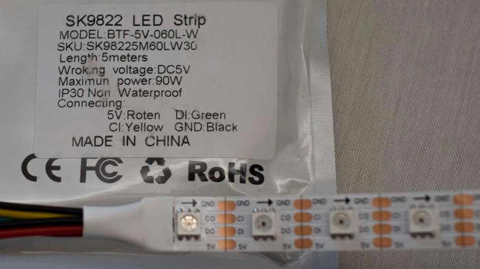
This particular package had a label which described the role of each wire. Not all of them have this information presented, and we have to determine 5V and GND rails using a meter. But even when we have a convenient label this time around, it is still worthwhile to double check. Not every LED strip vendor follows wiring convention: the red wire is not always 5V and the black wire is not always GND. Getting it wrong could destroy both our LED strip and our Pixelblaze. [UPDATE: Good news! Pixelblaze V3 features reverse polarity protection so it would gracefully tolerate reversed +5V / GND without damage, until we realize our mistake and rewire it correctly.]
Thankfully these strips were designed to be cut to length, with solderable pads for each of the four lines. This means we have conveniently accessible pads to check for continuity between a GND pad and (what we believe to be) GND wire, and 5V pad to 5V wire.
![]() Thankfully it is less critical to get data and clock lines right. A mixup would mean nonsensical patterns or no patterns at all, but no permanent damage. For this particular strip, the data and clock lines were inverted from the order on Pixelblaze circuit board hence the yellow/green crossover visible in this picture.
Thankfully it is less critical to get data and clock lines right. A mixup would mean nonsensical patterns or no patterns at all, but no permanent damage. For this particular strip, the data and clock lines were inverted from the order on Pixelblaze circuit board hence the yellow/green crossover visible in this picture.
The row of headers visible on the right is an expansion bus, capable of hosting the optional sensor expansion board which I plan to incorporate into this project down the line.
Because I had configured my strip settings to be at low (10%) brightness, I could power this entire rig with a portable USB power bank advertised to deliver up to 2A. This was enough to verify I could run prebuilt patterns on my newly connected LED strip. But how much more power might this setup draw? Time to do some math and figure it out.
![]()
(*) Disclosure: As an Amazon Associate I earn from qualifying purchases.
