More Non-Photorealistic Rendering

Today’s post is an appreciation for the continued evolution of computer animation using non-photorealistic rendering. The previous post has more details and words, today is more about the embedded YouTube videos.

I first learned about this technique from Disney’s animated short Paperman. (Watch on Disney+.)

Which evolved to Feast, another Disney animated short. (Watch on Disney+)

For behind-the-scenes reasons I don’t know, this technique hasn’t made it to a Disney theatrical release. Concept art were released for Bolt and Tangled showing they had ambitions to adopt this visual style, but both of those final products were rendered in a photorealistic style. We can see bits and pieces of the ambition left in those film, though, in bits of art visible in the background.

Whatever the reason, it left the door open for Sony Pictures to take the lead with Spider-Man: Into the Spider-Verse.

Members of that team followed up with The Mitchells vs. The Machines. (Watch on Netflix.)

Thankfully those were great films in their own right, independent of their novel visual style. I enjoyed them very much and their success opened the door (or more accurately, loosened studio wallets) for more and I am looking forward to them. Not all of them will be great films, nor would they necessarily succeed in pushing the state of the art, but I’m glad to see it happen.

The Bad Guys might be fun. Plot-wise, it doesn’t feel fresh after Wreck-It Ralph. In terms of visual style, it is the least adventurous relative to its contemporaries. Perhaps the technology team at DreamWorks/Universal Studios needed to keep things manageable for their first run.

If so, then I’m thankful that film paved the way. Puss in Boots: The Last Wish has a much more distinct visual style, and this trailer is hilarious. It had its theatrical run recently so I should be able to access a home video digital rental or purchase soon.

And now Paramount Pictures is trying it out as well, as seen in the recently released trailer for Teenage Mutant Ninja Turtles: Mutant Mayhem. I love this art style, especially how it is so distinct from the others on this list. (I don’t know my art terminology… “rougher” or “sketchier” doesn’t seem to quite cut it.) This trailer is a lot of laughs and I hope the visual style pair well with another reboot of the TMNT franchise.


Outside of films, there are shows like Arcane (on Netflix)

This will show up in more places, in more formats, in the years ahead. It looks like there’s already too much for me to see them all myself, which honestly is a fantastic problem to have.

Inspiration From Droids of Star Wars

Today is the fourth day of the month of May, which has grown into “Star Wars day” due to “May the Fourth” sounding like that film’s popular parting line “may the Force be with you.” A quick search confirmed I’ve never explicitly said anything about Star Wars on this blog and that should be corrected.

By the time I saw Star Wars, I had already been exposed to popular science fiction concepts like space travel, interstellar commerce, and gigantic super-weapons. And the idea of a cult that promises to make their followers more special than regular people… we certainly didn’t need science fiction for that. So none of those aspects of Star Wars were especially notable. What left a lasting impression was R2-D2.

R2-D2 had its own expression of duty and loyalty. Companion to humans, and a Swiss Army knife on wheels. A character that managed to convey personality without words or a face. R2-D2 was the most novel and compelling character for me in the film. I wouldn’t go far as to say R2-D2 changed the path of my life, but there has definitely been an influence. More than once I’ve thought of “does this help me get closer to building my own R2” when deciding what to study or where to focus.

I was happy when I discovered there’s an entire community of people who also loved the astromech droid and banded together to build their own. But that turned to disappointment when I realized the dominant approach in that community was focused on the physical form. Almost all of these were remote-controlled robots under strict control of a nearby human puppeteer, and little effort was put into actually building a capable and autonomous loyal teammate.

I can’t criticize overly much, as my own robots have yet to gain any sort of autonomy, but that is still the ultimate long-term goal. I love the characters of R2-D2 and the follow-on BB-8 introduced in the newest trilogy. Not in their literal shape, but in the positive role they imagined for our lives. This distinction is sometimes confusing to others… but it’s crystal clear to me.

Oh, I thought you loved Star Wars.

Star Wars is fine, but what I actually love are the droids.

I still hope the idea becomes reality in my lifetime.

Dell Latitude E6230: Blank ExpressCard Placeholder Is Also A Ruler

I found a fun little design while looking over the refurbished laptop I had bought. It was a Dell Latitude E6230, which had an ExpressCard slot. I’ve never used a laptop in a way that required add-on hardware. No PCMCIA, no ExpressCard, etc. Few of my laptops even had provisions for an expansion slot. But I remembered one of them — an old Dell XPS M1330 — included a little bit of creativity. Rather than the typical blank piece of plastic placeholder, the expansion slot held an infrared remote control with simple media buttons like “Play”, “Pause”, etc. This lets people use the little laptop as a media player where they can sit back away from the keyboard and still be able to control playback.

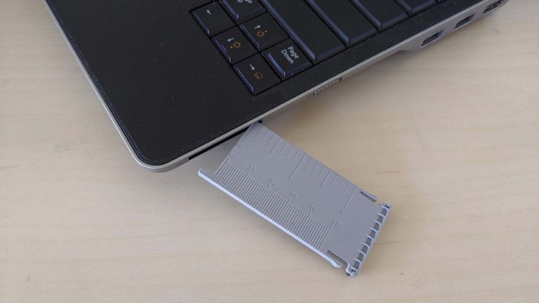
This laptop is from Dell’s business-oriented Latitude line, so it would not be keeping with product position to have such entertainment-oriented accessories. But I was curious if it had more than just a blank piece of plastic placeholder. So even though I had no ExpressCard to install, I popped out the blank to take a look. I was happy to see that someone put some thought into the design: the blank plate is a small ruler with both inch and millimeter measurements.

This feature cost them very little to implement, and it would never be the make-or-break deciding factor when choosing the laptop, but it was a fun touch.

Overlooked Gem: The Princess and the Frog

Ten years ago today, The Princess and the Frog opened to general theatrical release. At first glance, people saw hand-drawn animation in a computer-animated world, retelling an old fairy tale in the 21st century. As a result, people did (and still do) dismiss the film as out of date without taking a second glance. Which is a shame, because it is a wonderful film that can stand tall among all its modern contemporaries.

For photorealistic detail, state of the art computer animation in 2009 had long surpassed what hand drawn animation could deliver. This has happened before: painters used to focus on realism, but once color photography could handle all the realism we would want, good painters switched focus on applying their art in ways a camera could not. Similarly, good hand drawn animation projects would focus on their strengths. My favorite example in this movie were the dramatic changes in tone and style employed during the Almost There and Friends on the Other Side sequences. There are times when hand-drawn animation is the best tool for the storytelling job.

It also helps that beautiful art is backed by fantastic music. Of course, a film set in a fictional historical New Orleans couldn’t go without music, and this film delivered one of the best soundtracks of any film. Animated or otherwise.

This film was lovingly made by people who appreciated the art of hand drawn animation. From the high level executives who approved the project, to the Disney alum directors who returned to tell great stories, to the individual animators drawing the subtle curves found within every frame. The team had high hopes that Princess and the Frog would herald a new age of Disney animation.

Alas, it was not to be. Audiences remembered the lackluster low-budget animation projects that had come before, too much inertia for a single film to overcome. Still others dismissed it as a plot they’ve already seen, missing out on the unique twists offered by this particular version. And worst of all, getting the word out for this film proved to be impossible: promotional efforts were drowned out by advertising for James Cameron’s mega project Avatar, which would open a week later to herald a new age of 3D cinema. (It didn’t do that, either, but that’s a different topic.)

Disney released one more hand drawn animated feature film two years later with Winnie the Pooh. Both of these films were far more successful than Home on the Range that proceeded them, but still farther short of The Little Mermaid and Aladdin who were credited with building the previous peak of Disney animation. With blockbuster success of the computer-animated Frozen, Disney hand-drawn animation retreated from the big screen except for small appearances like “Mini-Maui” in Moana.

But as long as there are bored creative kids and blank corners in paper notebooks, there will be hand drawn animation. And Disney has no monopoly on the art form: smaller projects alive and well, delivered via new channels like YouTube. I’d like to believe hand-drawn animation is only waiting for the right combination of story, artistry, and audience to make its next great return to the big screen.

In the meantime, The Princess and the Frog is available for digital purchase at all the usual outlets (here’s my Amazon affiliate link) and is available for streaming on Disney+.

Very High Capacity Emergency Escape Stairs at IKEA Burbank

A luxury of living in the Los Angeles area is having my choice of IKEA furniture stores. Loved worldwide, many fans have to make a long drive to their nearest IKEA (some of them crossing national borders to do so) but I have several within easy driving distance to choose from.

I typically get my IKEA fix at their Covina location, but recently I had some time to kill near their Burbank location and decided to stop by and check it out. “IKEA Burbank” moved from another building within the past few years to this new building. I’m sure this meant updates conforming to the latest building codes, but nothing stood out in the interior. It felt much like any other IKEA from the inside.

There are a few interesting notes outside, though. The parking lot featured ample wheelchair access and other modern amenities like electric car charging stations. Sadly the latter were occupied by selfish people who parked their non-electric cars in those spots. A roundabout managed traffic at the entrance, hopefully not too confusing to American drivers.

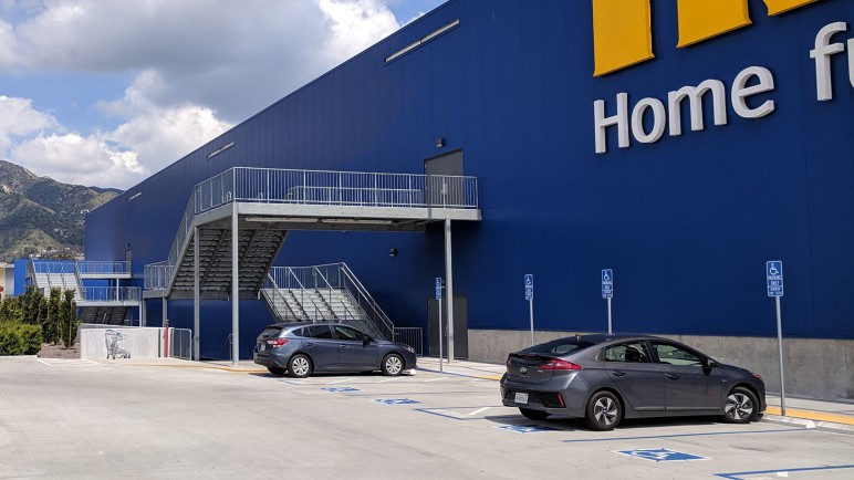
But what really caught my eye were the emergency escape stairways. Most emergency escape stairs are narrow and steep affairs that, in the best of times with no pressure, would be challenging to traverse. I hate to imagine who would get trampled on those stairs when flooded with panicked people in a rush.

These stairs, in contrast, are gigantic. Easily at least triple the width of any other escape stairways I’ve ever noticed outside of buildings. I associate stairs of this size more with prime locations within Disneyland, who are masters at crowd flow management. These stairs are wider than associated doorways, which makes sense as people can go through doorway faster than they can walk down stairs, requiring wider stairways to accommodate the same volume of bodies. Everything looks well set up for a speedy and orderly evacuation from this showroom warehouse.

It looks like a great contingency that most visitors will never notice, and as much as I’m fascinated by this design, I hope we never need to test the emergency evacuation capacity of this IKEA.

Concept to Production: Mazda Vision to 2019 Mazda3

A year and a half ago I went to the LA Auto Show to look at Mazda’s Vision Coupe concept car. It was a design exercise by Mazda to guide their future showroom cars, and more interesting to me, they stated a deliberate intention to explore ideas that do not necessarily photograph well. They believed making these sculpted curves look interesting in motion and in person would be worthwhile even if they don’t look as good in pictures. I thought they did an admirable job, enough that I felt guilty documenting my observations on this blog where I could only post pictures.

So, with the caveat that these pictures don’t look as good as the real thing in person, I examine the first implementation. See how the wild ideas on a concept car survived translation to a production car on the dealership floor: the 2019 Mazda3 Sedan. These started trickling in to dealerships a few months ago, and a search of online inventory indicated a few were in stock at nearby Puente Hills Mazda. I stopped by to find a silver sedan in front for comparison against the concept car.

Front three quarter2019 Mazda3 sedan front-three-quarters

There were a few elements that were never going to make it into production: those gigantic wheels and tiny rearview mirrors being the first to go. However I was a little sad at some of the other changes. A few of Vision’s clean long lines have been broken up in the production car. One significant line traced from leading edge of hood, met base of windshield, and became bottom edge of the windows. On the production car, that hood crease climbed up on pillar, no longer lining up with bottom window edge. A separate line on the concept car started at headlights, curved over front wheels, stayed parallel to bottom edge of windows, and blended into tail lights. On the production car this line started up front but dropped off on driver’s door and faded away into nothing. Another line started from base of rear window and led to top edge of trunk. I would have liked to see those characters survive but the car still looks pretty good in their absence.

As expected, Vision’s dramatic LED headlights and surrounding visuals did not make it to production. Only the vaguest of hints are still present.

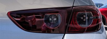
The tail lights fared a little better in translation, but only in comparison to the headlights. It did pick up central LED elements and added a few more, and the rocket nozzle kind of survived in the form of embossed grill shape and not a ring of LEDs. Big dramatic horizontal line mostly disappeared but a few segments of horizontal styling are still there.

As expected, Vision’s multi-layered three dimensional nose was sadly flattened to comply with pedestrian protection and crash safety laws.

Mazda is making an effort to move upstream, elevate themselves above the Toyota / Honda / Nissan product line but maybe not quite up to their Lexus / Acura / Infiniti luxury counterparts. Mazda has yet to earn my money in this effort, but their exterior styling team is certainly doing their part and doing it well.

Padadena Chalk Festival 2019

This past weekend was spent looking over artists working intently at Paseo Colorado for Pasadena Chalk Festival 2019. I feel it is to chalk artists what badge hacking at Supercon are for electronics people. Since I never graduated beyond the kindergarten stage of chalk art, I learned about surprising variety of tools and techniques for applying chalk to concrete. As someone who loves to learn about behind-the-scenes of every creation, it’s fun to revisit certain favorite pieces to see them progress through the weekend.

There were many original works, but most of my attention were focused on recreations of animated characters and scenes I’ve already seen. A notable departure from this pattern was a large mural depicting space exploration including my favorite Mars rover Curiosity:

Monsters, Inc. characters by Jazlyn Jacobo:

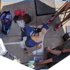
Kiki’s Delivery Service:

Aladdin’s Genie and Carpet play a game of chess. Drawn by Jen:

A scene from Toy Story 4 teaser, drawn in front of the theater which will be playing the movie next weekend. Drawn by Gus Moran:

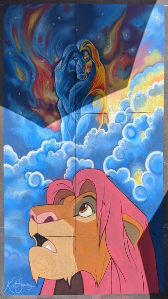
Lion Kings Simba and Mufasa by Kathleen Sanders. This was quite fitting since it was also Father’s day:

Grandfather and grandson from Coco feature in this highly detailed composition by Patty Gonzalez:

Other works I liked:

This artist, who is drawing a chalk portrait of Luke Skywalker as X-Wing pilot, brought along a 3D prop in the form of a full-sized R2-D2.

Chalk festival R2D2

The most novel piece was by C.Nick in the Animation Alley. Here I expected to find artists working with animated characters… I was delighted to find an actual animated chalk drawing.

Chalk festival C Nick tinkerbell

Chalk-Tinkerbell


LEGO 41611: BrickHeadz Marty McFly and Doc Brown

Today will be a little holiday break from the usual fare… it’s time to play with LEGO bricks!

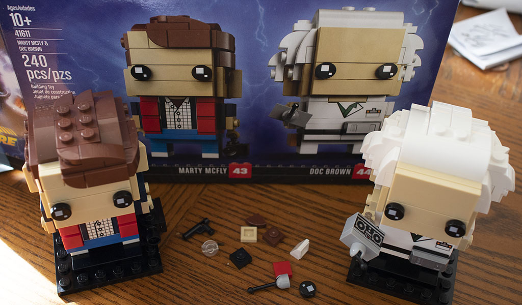
I count Back to the Future as one of my favorite movie series, a fact known to most of my friends. So it’s no surprise that I had been gifted a Back to the Future themed LEGO set. Kit #41611 from their “BrickHeadz” line of caricature figurines represented our stars Doc Brown and Marty McFly. This is my first BrickHeadz set and I was very curious to see how they would come together.

Our heroes are depicted as they were at the beginning of the first movie, when Doc demonstrated time machine operation for the first time in the parking lot of Puente Hills Twin Pines Mall. Marty is in his puffy 1985 jacket holding a VHS camcorder, and Doc is wearing his white lab coat with radiation symbol on the back and holding the car’s remote control.

These kits minimize appearance of LEGO studs, using a lot of smooth pieces to create the desired appearance. This is especially apparent in the face and hair. Marty had many smoothly curved pieces, whereas Doc had a much more random jumble of pieces to represent his wild Einstein-like hair.

When I poured all the pieces out on the table, I wondered about a few pieces that were brightly colored in a way that did not match the color theme of the character. As I followed instructions, I learned these pieces would not be visible when properly assembled. Hence these oddly colored pieces were designed to be a visual indication if assembly should go wrong. Here’s a partially complete Marty, the bright pink and bright green pieces sit inside the body and head, invisible when properly assembled.

LEGO 41611 1 partial Marty

Once Marty was complete, it was time for Doc. Again, the bright pink, yellow, and green pieces would not be visible when properly assembled.

LEGO 41611 2 Marty done time for Doc

And here is Doc and Marty, ready for their adventures through time. It’s very generous of LEGO to give a few extra small pieces that are easy to lose. Assembling both of them consumed approximately 30-45 minutes, and I enjoyed every minute of it.

LEGO 41611 3 Doc and Marty


SGVHAK Rover Interface Avoids Confirmation Dialog

Shutdown Reboot

Our SGVHAK Rover’s brain prefers to be shut down gracefully rather than having its power removed at an arbitrary time. If power cuts out in the middle of a system write operation, it risks corrupting our system storage drive. While our control software is written to be fairly platform-agnostic, we’re primarily running it on Raspberry Pi which lacks a hardware shutdown button. So we need to create an UI to initiate a system shutdown via software.

The easiest thing to do would be to add a “Shutdown” button. And since it is a rather drastic event, have a “Are you sure?” confirmation dialog. This historically common pattern is falling out of favor with user interface designers. Computer users today are constantly inundated with confirmation dialog making them less effective. If our user has built up a habit of dismissing confirmation dialog without thinking, a confirmation dialog is no confirmation at all.

So how do we enforce confirmation of action without resorting to the overplayed confirmation dialog? We have to design our UI to prevent an accidental shutdown from a wayward finger press. To accomplish this goal, our shutdown procedure is designed so user must make a deliberate series of actions, none of which is “Yes/No’ on an ineffectual dialog box.

First – our user must enter a “System Power” menu. If they entered by mistake, any of the three active buttons will take then back to main menu. There’s no way to accidentally shutdown with a single mistaken tap.

Second – they must select “Shutdown” or “Reboot”, forcing a deliberate choice to be made before our UI activates “OK” button. If an incorrect selection is made, it can be corrected without accidentally triggering the action because both options are on the far left of the screen and “OK” is on the far right. Bottom line: Even with two accidental presses, our system will not shut down or reboot.

Third – With the “OK” button now activate after two deliberate actions, the user can tap it to begin the shutdown (or reboot) process.

SGVHAK Rover Steering Trim Adjustment

One of the changes we made to our SGVHAK Rover relative to the baseline design was a decision to omit absolute encoders for our corner steering motors. The baseline design used absolute encoders so it knows every wheel’s steering angle upon system startup, but we decided to sacrifice that ability in exchange for cost savings (~$50/ea * 4 corners = ~$200.) Since there is no free lunch, this decision also means we have additional work to do upon our system startup.

Our control software launches with the assumption that all steerable wheels are pointed straight front-back, which is of course not always true. We could manually push the wheels to straight front-back orientation before turning on power, but that’s not great for the gearbox. Also, the shaft coupler used to connect our motor gearbox to our steering mechanism is liable to slip. (This is considered a bug even though it has a potential feature: in theory sharp jolts to the system would slip the coupler instead of breaking something else in the system. In practice, we found that it didn’t slip enough to avoid breaking a gearbox.)

Given both of these scenarios, we need a software-based solution to adjust steering trim on the fly. Once our RoboClaw motor controller is told where zero degree position is, it is quite capable of holding a commanded angle until the coupler slips or the system reboots, whichever comes first.

Steering Trim

Steering trim adjustment took the form of a multi-stage HTML form designed for our specific workflow. First our user chooses a wheel to work with, and they are directed to do so because every other UI element on the page is inactive until one wheel is chosen.

Once a wheel is chosen, the remaining UI activates and wheel selection UI deactivates to guarantee we’re working on a single wheel at a time. In this stage, steering angle can be adjusted in 1- and 5-degree increments. When we’re satisfied our wheel has been returned to zero degrees deflection, we can select “Accept Current Angle as New Zero” to commit. We also have the option to abort adjustment and retain previous zero position. Either way, wheel selection activates to allow user to select another wheel, and the rest of the page deactivates until a wheel is chosen.

We have no scenarios where multiple steering motors need to be trimmed at the same time, so this user experience specifically focus on one wheel at a time makes the process straightforward. It also becomes impossible to make mistakes caused by user thinking they’re adjusting wheel when they’re actually adjusting another, which is a good thing for positive user experience.

Someone Put a USB Plug Inside a USB Plug

Today we point our spotlight at one method of supporting multiple USB plug form factors in the most compact layout possible: putting a (micro) USB plug inside a USB (type A) plug. It doesn’t look terribly robust or reliable for the long term, but it is indeed extremely compact and clever in its own Rube Goldberg way.

Gigastone 32GB USB Contraption

The mechanical engineer who devised this contraption took advantage of the fact a micro USB plug’s entire outer dimension is physically smaller than the “tongue” part of a USB type A plug. And conveniently, all the pins are electrically identical so they are easy to route. From there it’s a matter of creating the small sheet metal hinge for the exterior surround of type A portion of the plug so the user can swing it out of the way and expose the micro USB plug embedded within.

Usually smaller flash memory brands assemble their product from spot market purchases and other similar existing large volume products. Gigastone is not one of the bigger names.  Given this, the initial assumption (fair or not) was that this plug is a catalog item somewhere. But if so, it’s not obviously available from Digi-Key or Mouser.

Given the lack of immediately obvious source, we’ll tentatively assign credit for this clever design to Gigastone and their team behind this particular flash drive. Good job, guys, this item’s cleverness managed to stand it out amongst the crowd of commodity flash drive offerings.

Remo+ DoorCam Cleverly Solves Installation Challenges

Personally I’m on the skeptical side of the current smart home wave. The cost/benefit ratio still doesn’t work well enough to justify the purchase, with the single exception of a Nest Thermostat which has paid for itself by turning down the heat when I am away. But skepticism doesn’t prevent me from appreciating a clever design when I see it.

There’s been a few products that try to make a smart front door. From a digital keypad lock to a fully internet connected front door monitoring system. The problem is that most products require some sort of hardware (in the Home Depot sense) modification that is not always possible. For example people living in apartments are not allowed to replace locks, drill holes in the door, or run wires in the walls. A nondestructive stick-on solution outside the front door would meet those requirements, but is in turn vulnerable to theft.

As soon as I saw a picture of the Remo+ DoorCam I realized their proposed solution and its simplicity: hook it over the top of the door. This keeps the majority of electronics inside while still presenting the camera outside, and installation is a quick and easy job which does not require anything from a home improvement store. The design has some limitations on the thickness of door, and the camera lens is still vulnerable to vandalism, but thieves can’t just pull the whole unit and walk off with it.

Simple and effective: hallmarks of a cool innovative design.


DoorCam_Side_Image_CES_1024x1024@2x

Mazda Vision Coupe: Design Highlights

Different people go to an auto show to see different things. My personal target for the LA Auto Show was a concept car in the Mazda pavilion: the Vision Coupe. Mazda unveiled it at the Tokyo Auto Show a little over a month ago and it has been pretty well received. When I found out Mazda would bring it to Los Angeles I had to go see it for myself.

Front three quarter

A significant aspect of the design is the evolution away from creases in the sheet metal. About ten years ago the Mazda Nagare concept car illustrated the use of creases, and the idea spread through the Mazda line. I thought the show car was novel but I am not a fan of the translation into production cars. While some of the creases do illustrate a story flowing from one design element to another, too many of the creases feel forced. They form from seemingly nowhere and fade out to nothing, contributing little (or distracting from) the story told by the overall shape of the car.

With the Vision Coupe (and the RX-Vision before it) Mazda design declared sharp creases are played out. Moving on to the smooth sculpted surfaces has a risk – they do not show up on photographs as well as creases. So Mazda risks losing sales with people who car-shop by looking at pictures. Photos miss the full impact of the design that can only be appreciate by seeing how lights reflect and move around the body. I look forward to seeing how these ideas translate to Mazda showrooms.

Headlight

Another idea I want to see translated to production are the lights. We’ve had big round headlights for most of the history of the automobile. With the introduction of compact LEDs bright enough to be headlights, designers now have new flexibility and explored different styles of LED illumination. Some designs weren’t very bold and laid out the LED in a straightforward grid. Some tried to spread them in a creative pattern, but an array of LEDs can easily make people think of arthropod eyes which can be unsettling. Some of those designs have been quite polarizing.

The solution presented on the Vision Coupe concept is to take the LEDs and form them into a circle so our human anthropomorphic brains can see an eye. But not limit it to a circle – the design plays with a line of light that carries through the eye (but doesn’t cut into the ‘eyeball’) and also with the shadows cast by the sculpted surround that evokes eyelids. Futuristic yet familiar. I like this design though I’m not sure it’ll survive translation to production. There are a lot of legal requirements on headlights that are difficult to satisfy and so are usually ignored in show cars.

Taillight

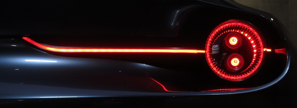
On the opposite end, the taillights use a similar theme of a line of light through a circle. But now, rendered in red, the circles look like rocket engine exhausts instead of eyeballs. There are far fewer legal requirements around taillights so I hope this translates intact to some future showroom Mazda.

Sharp nose

The final detail that really attracted me is the staggered levels of the nose, led by the hood that ends in a sharp beak. Sleek and full of personality, it sadly has no chance of surviving translation to production. Real production cars need front bumpers, license plate holders, and are not allowed to cut pedestrian legs off at the knee.

But it does look awesome.

Waiting For Efficient Voice Control

When I started playing with computers, audio output was primitive and there were no means of audio input at all. Voice controlled computers were pure science fiction. When the Sound Blaster gave my computer a voice, it also enabled primitive voice recognition. The mechanics were primitive and the recognition poor, but the promise was there.

Voice recognition capabilities have improved in the years since. Phone-operated systems have enabled voice controlled menus within in the past decade or so. (“For balance and payment information, press or say 4.”) It is now considered easy to recognize words in a specific domain.

Just within the past few years, advances in neural networks (“deep learning”) have enabled tremendous leaps in recognition accuracy. No longer constrained to differentiating numbers, like navigating a voice menu, the voice commands can be general enough to be interesting. And so now we have digital assistants like Apple’s Siri, Google’s Assistant, Amazon’s Alexa, and Microsoft’s Cortana.

But when I tried to communicate with them, I still feel frustrated by the experience. The problems are rarely technological now – the recognition rate is pretty good. But there was something else. I had been phrasing it as “low-bandwidth communication” but I just read an article from Wired that offers a much better explanation: These voice-controlled robots are designed to be chatty.

Chatty Bots
Link to “Stop the Chitchat” article on Wired

The problem has moved from one of technical implementation (“how do we recognize words”) to one of user experience (“how do we react to words we recognize”) and I do not appreciate the current state of the art at all. The article lays out reasons why designers choose to do this: To make the audio assistants less intimidating to people new to the technology, make them sound like a polite butler instead of an efficient computer. I understand the reason, but I’m eager for the industry to move past this introductory phase. Or at least start offering a “power user” mode.

After all, when I perform a Google search, I don’t type in the query like I would to a person. I don’t type “Hey I’d like to read about neural networks, could you bring up the Wikipedia article, please?” No, I type in “wikipedia neural network

Voice interaction with a computer should be just as terse and efficient, but we’re not there yet. Even worse, we’re intentionally not there due to user experience design intent, and that just makes me grind my teeth.

Today, if I wanted a voice-controlled light, I have to say something like “Alexa, turn on the hallway lights.

I look forward to the day when I can call out:

AZIZ! LIGHT!


Acrylic Lights: Infinity Mirror

I’ve played with putting lights in my 3D-printed creations for glowing illumination effects. There were limits to what I could do with 3D printing, though, because printing with a clear filament does not result in a clear object. In contrast, acrylic is clear and works as a light guide with a lot of possibilities.

I’ve noticed a few attention-getting light effects in my acrylic projects to date, most of them created by happy accident. The acrylic box with external fixture made good use of external light. The Portable External Monitor version 2.0 was built from stacks of acrylic sheets: its fluorescent back light reflected between the layers like an infinity mirror.

PEMv2_InfLights

This effect was on my exploration to-do list for the future, but I moved it to the top of the list after seeing surprisingly good results on the FreeNAS Box v2 enclosure.

I had planned for it to have the standard PC status LEDs: one for power, and one for disk activity. The acrylic plate for motherboard mounting spacer also had two cutouts for 3mm LEDs along the center line. The red hard drive activity light is to be mounted high, and the blue power light mounted down low. The idea was for the blue light to illuminate the top edge of the plate. When there is hard drive activity, red LED will light up the center of that edge, and it should blend to purple with the power light. Both LEDs were blocked from direct view by the motherboard, so all we should see is a nice soft glow emitting from behind the motherboard.

FreeNASv2LightPlan

That was the plan, the reality was different. The red activity light worked as expected: when there is disk activity, the center of the top edge had a little red glow.

The blue LED decided to ignore my “nice soft glow” plan and put on an extravagant light show. It didn’t just light the top edge, it lit every edge of that acrylic sheet and had plenty of extra light energy to throw on the surrounding shelving.

FreeNASv2_LightsAbove

Here’s a close-up of the sideways illumination.

FreeNASv2_LightsSide

The many rays visible in the side illumination, as well as the lines making up the top illumination, indicate infinity mirror action going on inside that sheet. It wasn’t directly visible, and probably very difficult to photograph even if so. Without internal reflections, the blue light would have just gone straight up. But with the smooth surfaces and edges of the acrylic reflecting inside the sheet, the light of a single LED bounced around, found different angles, and was emitted in many more directions.

This LED illumination effect warrants further investigation. It is a happy accident that I fully intend to learn from, and put into future acrylic projects.

I want every acrylic project to look this awesome!


FreeNAS Box v2: Construction Fixture

One of the problems with FreeNAS Box v1 was that I designed it with tabs and slots to fit into each other. While it made the box easy to assemble, the slots severely weakened the structure of the box.

For FreeNAS Box v2 I avoid the tabs and slots. But I need something else in their absence to help me during construction. The answer is a fixture: Something I design along with the box that helps me build it, but not part of the end product.

Building the box will start with bonding all the major vertical pieces together. Once the cement has set hard enough for them to stand alone, the fixture pieces can be removed. The resulting assembly will then be self-supporting as the remaining pieces are attached.

The fixture pieces sit top and bottom. Pretty much where the largest horizontal pieces would eventually go, but are distinctly different from those pieces.

FreeNASv2 Fixtures.JPG
Initial assembly (gray) with assembly fixture (yellow)

The top fixture has two slots for holding two of the vertical sheets of acrylic. We’ve already established such slots are bad for the structural strength of the end product, but it’s perfectly OK (and quite useful) to have them in a fixture.

Both the top and bottom fixture have round cutouts in the corners and in the mid-span T-joint so that they stay clear of any extraneous acrylic cement that might leak out. This way we avoid accidentally cementing the fixture to the product.

Each of the fixture is made of two layers of acrylic, a main layer and a secondary layer whose shapes helps keep the box pieces in place. The small round circles visible in the picture is sized for M4 screws to fasten the fixture layers together. Using screws instead of acrylic cement allows us to later disassemble the fixture and recycle the pieces as scrap acrylic in future projects.

FreeNAS Box v2: Airflow Design

Designing the system airflow for thermal management is a huge consideration for the FreeNAS box design. The two fans in the system have been oriented for easy inspection first and then the airflow was designed second to work with natural convection flow. Lacking skills to use sophisticated thermal modeling and analysis tools, this design is mostly based on intuition.

Working as a network attached storage device is not a very computationally intensive task. Plus the CPU has its own fan, so thermal control of the processor is not a primary concern. The power supply also has its own fan, which I assume can take care of itself.

That leaves the hard drives as the primary thermal concern. Lacking their own cooling fans, the airflow design of the case will put them first in line to receive the coolest air. This meant placing them right at the intake. The v1 intake was on the bottom, so that’s where the drives were. The v2 intake air from the side, and again that’s where the drives were placed.

After the intake air has met the hard drive, the warmer bits should flow up and over the top of the hard drive, carried by convection towards exhaust. The cooler bits should head towards the rest of the case, helping to cool the motherboard and the CPU.

The motherboard and the CPU is in its own chamber. Cold air comes in the bottom and sides of this chamber and the top of this chamber has holes to send its warmest air into the power supply fan for exhaust.

If this proves to be inadequate cooling for the motherboard, we have the option of cutting an air intake hole directly in the front door panel of the case.  The CPU fan can then pull in cool air from the outside. This will reduce the amount of air drawn in past the hard drives, though, so I wanted to see how well it works before I start cutting holes.
 

FreeNASv2 Thermal Flow 2

FreeNAS Box v2: Additional Goals

We’ve just established all the problems exposed by the v1 prototype that we want to address for v2. In addition to those issues, we also want v2 to cover a few things that are no fault of the v1 prototype.

First one is relatively obvious: actually build a complete and usable case. I knew I was trying new ideas in v1 and that something will go wrong, so it wasn’t really complete. Even if everything went right (I knew it wouldn’t) I would have had to build a v2. For one example, I didn’t bother to design an access door.

We then have a few separate items that relate to improving space efficiency.

When I placed v1 on the shelf where I expected to keep my FreeNAS box, it wasted a few inches between the back and the wall due to the angle of the power cable. I want to rearrange things so that the back of the box can sit flat against the wall.

Cooling path in v1 started with air intakes on the bottom of the case. This was part of the tribute to the Apple PowerMac G4 cube, but functionally unnecessary while consuming vertical space.

Also contributing to the vertical space consumption was pointing all the ports downwards, like the PowerMac G4 cube. This made the ports difficult to access. It would be good to align the direction of all the plugs, so power and network cables can be in parallel.

Out of all the requirements listed here and in the previous post, the greatest impact was the “make sure all fans are visible for easy verification they are spinning” goal. It meant rearranging the components so both fans face forward. This made for an interesting design challenge as it is against common convention of computer case design. Once I got that set up, the configuration was then further refined in Fusion 360 to satisfy all the remaining requirements until we have this: my FreeNAS Box v2.

FreeNASv2

FreeNAS Box v1 Problems

FreeNAS Box v1 was a good learning project for acrylic construction. Here are the issues with v1 I want to address for the next version.

  1. Non-orthogonal joints: The laser cutter only cuts right angle edges. v1 had a few joints that were impossible to cement because the edges didn’t align at right angles.
  2. Tab and slot construction: To help align joints, I designed v1 with tabs to fit into slots I had also cut into their mating surfaces. While this made the box easy to build, it destroyed durability of the end product. The sharp corners of the slots are where acrylic starts cracking under stress. I had known about the dangers of sharp internal corners, but I thought acrylic cement would bond everything together eliminating the weak point. This idea has now been proven false.

    FreeNAS1_Cracks
    Stress cracks that started at corners of slots.
  3. Unappealing tangle of wires: The v1 box design placed all of the wires up front, which turned out to look pretty ugly, and all the components (hard drives and the motherboard) were hidden under the mess.

    FreeNASv1
    Yes, there’s a computer under the tangle of wires.
  4. Difficult access to components: Besides looking bad, the mess of wires up front also blocks access to everything else. It would be difficult to perform maintenance such as replacing drives if they fail.
  5. Cooling fans vulnerable to jamming: The wiring paths were such that, if some wires should misbehave and bend slightly out of position, they would impinge upon the blades of cooling fans stopping them from turning.

    FreeNASv1_Flaw
    Several wires in this bundle poked into the fan grill where it does not belong.
  6. Cooling fans are out of sight: Compounding the problem of blocked fans is the fact that despite the clear acrylic exterior, it was not easy to notice the fans were blocked.

I had to physically build FreeNAS Box v1 before I knew known any of the above are problems. Some I had thought about and didn’t think would be a problem, the others I just hadn’t thought about at all.

FreeNAS Box V1 Design

FreeNASv1_CADOnce the components are gathered, we start thinking about designing an enclosure for them. The tool of choice is the Tux-Lab laser cutter. The material of choice is acrylic sheet. The objective of the exercise is to learn how to build with acrylic and ideally create something novel and unique.

Since my mind is already on acrylic, it was a short jump to think about the Apple Power Mac G4 Cube. A landmark of industrial design. Obviously what I make won’t be as pretty, but it’ll be my homage to the cube. Here are the two main design considerations in my FreeNAS experiment #1.

Hard Drive Cooling

Heightwise
Airflow along the sides has small surface area.

Lengthwise
Airflow lengthwise has large surface area, but will be obstructed by data and power cables.


Crosswise
Airflow crosswise has large surface area and will not be obstructed by data and power cables.

Since the goal is for low power, low noise, and small size, I didn’t want to add any fans. The small fan on the processor and the large fan in the power supply will take care of their respective components. That leaves the two hard drives without their own cooling, so the enclosure will have to utilize airflow created by the power supply fan.

We desire the maximum cooling surface area that presents the fewest obstructions to the air stream. And we want to work with (instead of against) natural convection forces. Evaluating the possibilities, the best choice is to align cross-wise airflow to be vertical by sitting the hard drives on their long sides.

Power Supply Spacing

PSU UprightFollowing the lead of the G4 Cube, air intake will be on the bottom and the power supply (with its fan) will sit at the top to work alongside natural convection and exhaust hot air.PSU Tilted

With the power supply sitting at the top, and the hard drives sitting on their sides against the bottom, that leaves a fairly large piece of unused space. The wires protruding from the power supply is also a concern. We either have to force those wires to make sharp downward turns to reach the system components, or we have to increase the depth of the enclosure to give the wires room.

Our experiment #1 tilts the power supply downward 30 degrees to utilize the available space to relieve the wire spacing issue.

Will these ideas work? Let’s build it and find out…