To me, the most interesting peripheral on the Pixelblaze Sensor Expansion Board was its accelerometer module. Its microphone seems to be a decently well-explored space, with multiple examples available on the pattern database, and I haven’t figured out how I would use the light sensor creatively. But there weren’t as many examples of using the accelerometer and I have a few potential ideas there.
The first task of playing with an accelerometer is to determine direction. From Pixelblaze documentation I know it will populate an array accelerometer of three elements for acceleration in X, Y, and Z axis. But which direction do each of these point?
Pixelblaze IDE makes exploration easy. Variables that are export-ed (like the variables to hold sensor values) can be watched live. This simple test program is enough to get started:
export var accelerometer = array(3)
export function render() {
}
Once entered, look for the “Vars Watch” window on the right hand side and a green “Enable” button.
![]()
Once enabled, Pixelblaze will display values of all exported variables and update them as the pattern is running.
![]()
Gravity is a constant acceleration towards the center of the earth, so we could tilt the Pixelblaze around and see which orientation shows the maximum positive number. The downward direction will be aligned with the axis showing the largest number while the other two are nearly zero. Once determined, jot them down in a notebook:
![]()
To double-check this answer, I went to look up the datasheet for the accelerometer chip itself. Looking on my expansion board, I saw the top was labeled with “*2815 C3H BCSHN” and a web search was inconclusive. Looking into Pixelblaze sensor expansion source code, I found comments marking code to talk with a LIS3DH accelerometer whose data sheet had the following diagram:
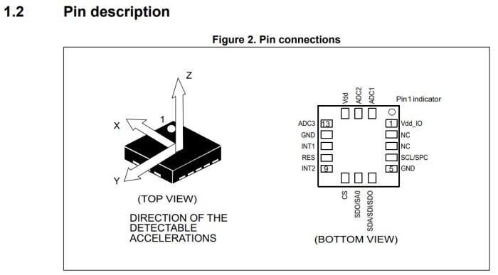
All three axis line up as my notes indicated, but their arrows point in opposite direction from mine. Perhaps there’s a convention I’m violating and the arrow actually points opposite of acceleration? This would allow the convenience of a Z pointing up when sitting flat where gravity is accelerating downwards.
Either way, this is enough information to continue. My earlier RGB-XYZ 3D Octants sample program was rewritten to add an accelerometer component. This way the colored blocks move around in response to physical movements of the LED helix. But the visual motion was not intuitive to a human, because my LED pixel mapper matrix does not align with my accelerometer axis. One way to solve that problem is with a new top end piece for my LED helix.
