Early on in this project I took a brief look at power requirements for a LED strip with 300 modules. I knew my project would not require maximum power but I didn’t know exactly how much until I got further in the project. Now that I’ve measured actual power consumption with it up and running, it’s time to put a new solution together.
The first and most important thing is safety, so I will have a fuse which is commonly neglected in one-off hobbyist projects. I’ll be using batteries which are rated to supply up to 150A. Nothing in Glow Flow can withstand that power in the event of a problem or a mistake. If that should happen, something will blow, might as well be a fuse whose job it is to do so.
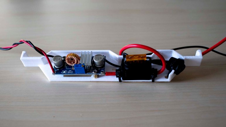
The second thing is the regulator module. I have MP1584 modules (*) that can deliver 2A and peak of 3A, and I have XL4015E1 modules (*) that could deliver peaks of 5A. I know Glow Flow at full brightness will demand at least 5A, with peaks of power draw beyond that when responding to sound stimulus. So the plan is to use two XL4015E1 modules, one for each half of the LED strip.

And finally, the convenience of a power switch so I would not have to disconnect and reconnect the battery all the time. All components were placed on a single tray that clips to the inside of Glow Flow cylinder. Leaving plenty of room for a second identical set of battery + power regulator board.
If I had a dual-pole switch I would use one to control my two parallel power supplies. But in my parts collection of compact power switches, I only had single-pole single-throw switches. So Glow Flow will have a switch for each of its two electrically independent power systems. Flipping two switches every time is not ideal, but not the end of the world. It’s only a slight annoyance for the capacity to finally run Glow Flow at full power.
(*) Disclosure: As an Amazon Associate I earn from qualifying purchases.
