Vertically Mounted Construction Experiment

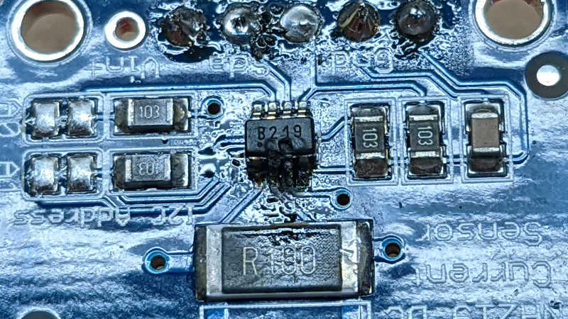
My experiments with IN219 DC voltage/current sensor started by monitoring the DC output of my solar storage battery, where I can count on a constant source of power and didn’t need to worry about going to sleep to conserve power. After I gained some confidence using ESPHome I tackled the challenges of running on solar panel power with an independent battery (salvaged from a broken USB power bank) and now the first version is up and running.

But that meant I was no longer monitoring the DC output and solar battery consumption… and I liked collecting that data. So I created another ESPHome node with its own INA219 sensor to continue monitoring power output, with a few changes this time around.

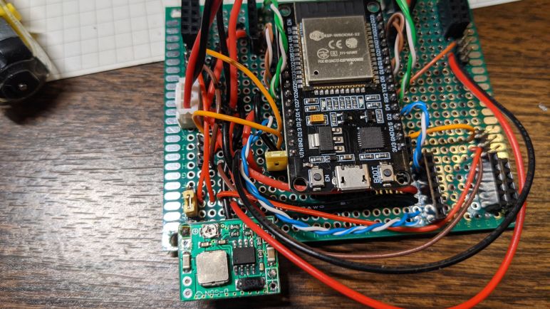
The biggest hardware change is switching from ESP8266 to ESP32. I have ambition for this node to do more than monitor power consumption, I want it to control a few things as well. The ESP8266 has very few available GPIO for these tasks so I wanted the pins and peripherals (like hardware PWM) of an ESP32. Thanks to the abstraction offered by ESPHome, it is a minor switch in terms of software.


Side note: I found that (as of today) https://web.esphome.io fails to flash an ESP32 image correctly, leaving the flash partition table in a state that prevents an ESP32 from booting. Connecting to the USB port with a serial monitor shows an endless stream repeating this error:

rst:0x10 (RTCWDT_RTC_RESET),boot:0x13 (SPI_FAST_FLASH_BOOT)
flash read err, 1000
ets_main.c 371 
ets Jun  8 2016 00:22:57

My workaround was to fire up ESPHome Docker container on an Ubuntu laptop for direct USB port access. This allowed an ESP32 image to be flashed in a way that boots up successfully. After the initial flash, I no longer needed the laptop as I was able to refine my ESPHome configuration via wireless updates.

My ESP8266 flashed correctly with https://web.esphome.io, no problems there.


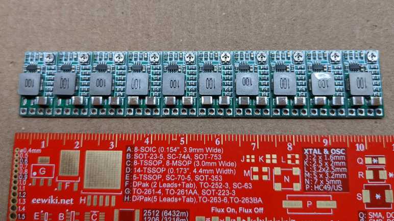
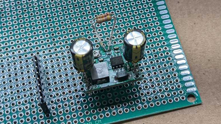
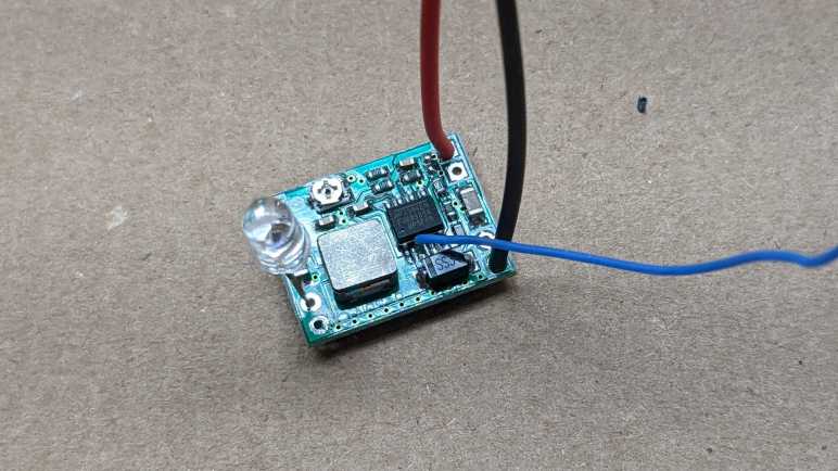
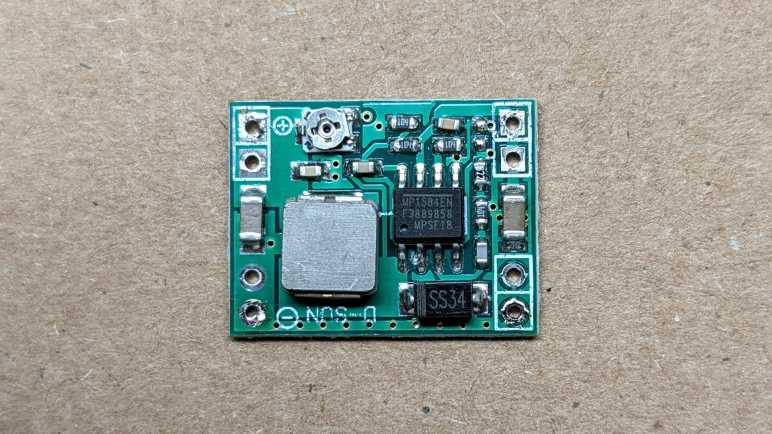
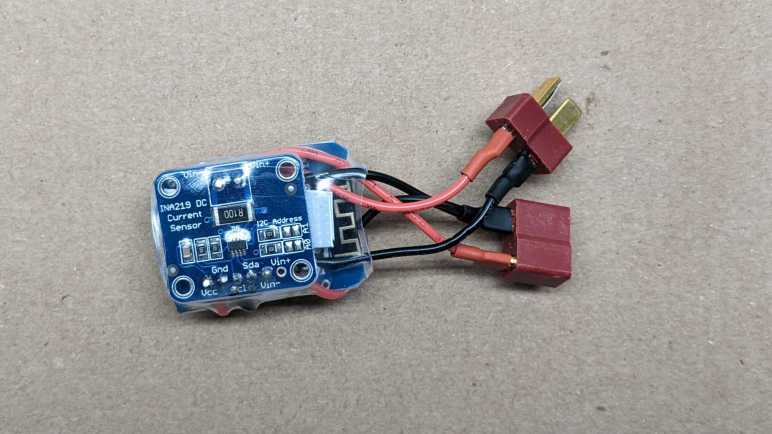
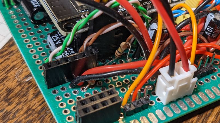
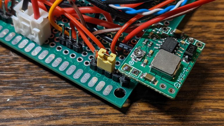
Back to the hardware: another experiment is trying to mount my various electronics modules on their edge to pack items closer together. This is pretty easy for things like my INA219 module and my new experimental buck converter board, which has their connectors all on one side of their circuit board. I did mount an INA219 on its edge as planned, but just before I soldered a buck converter, I changed my mind and went with a known quantity MP1584 module instead. It’s still mounted vertically, though, using legs of 220uF capacitors.

Since I expect to add various experimental peripherals for this ESP32 to control, I also added a fuse in case something goes wrong. (Generally speaking, I really should be incorporating more fuses in my projects anyway.)

The first experimental peripheral output on this board is a USB Type-A port connected to the 5V output of my MP1584. I’m starting out with a direct tap to verify everything worked as expected before I start adding ESP32 control. Thanks to vertical mounting, I have plenty of room left on this prototype board for future experiments like an aborted attempt to hack a USB Type-C cable.

Buck Converter Module with Enable Pin

After implementing over-discharge protection, attention turns to the charging portion of my project. For several of my projects over the past few years, I’ve been using a commodity buck converter module sold by many vendors. Built around a MP1584 chip (or a close-enough clone) they have worked quite well. But there were a few annoyances that made me want to try a different module.

  1. The first annoyance is that the commodity module is designed for variable output voltage adjusted via a tiny potentiometer. This gives great flexibility but it means every time I want to use a module I have to measure its output voltage on my voltmeter and adjust its potentiometer until I reached the voltage I wanted for a particular project. Most of the time I just want one of several common voltage values, usually 5V. It’d be nice to streamline that process.
  2. The next annoyance is that the MP1584 enable pin is not exposed on the module. There is an onboard voltage divider that automatically enables the chip whenever supply voltage rises above 3V. Usually this is what I want, but not always. And when I don’t want it, modifying the module is a hassle and prone to errors.
  3. And finally, the module’s connection pinout does not align with 0.1″ spacing, making its use on a perforated prototype board annoying. Recently I worked around this problem by adding capacitors to the input and output terminals then using those capacitor legs’ flexibility to compensate. But it would be nice if I don’t have to do that.

Looking over Amazon listings for “buck converter” I found an alternative candidate(*) advertised to address these annoyances. I bought a pack of twenty and it arrived in two bars of ten. We are to break off individual units like a candy bar. Some of the Amazon viewers complained, but I actually prefer this packaging over loosely packed individual modules. Here is the front and back of a single module:

The chip that runs the show is labeled AELH. This is different from Amazing listing pictures, which show a chip labeled AGCH. I found no information for either of those designations, so for the moment the exact identity of this buck converter chip is a mystery. For all I know, it might still be a MP1584 (or drop-in replacement) but that doesn’t matter right now. What matters is the rest of this module, which features an impressively compact layout.

Across the bottom we have four pins: VO+ (voltage output positive), GND (ground), IN+ (voltage input positive) and EN (enable). They have 0.1″ spacing, which I wanted for convenient prototype board/breadboard use.

There is a potentiometer in the top front corner, and six resistors below that. Looking on the backside we can see the potentiometer is connected but there are provisions for us to cut that trace and bridge one of the other pairs of pads to select one of the resistors that’ll give us a popular voltage, no fiddling with potentiometer required. I promptly cut the potentiometer trace and bridged the 5V pads with a bit of solder to see what I get.

I measured the output pins with my voltmeter, and it says 4.93V. This might be too low to avoid the dreaded lightning bolt icon used by a Raspberry Pi to signal low voltage, but should be good enough to charge a USB power bank.

Encouraged by this, I integrated this module into my solar monitor project. Where I found that the enable pin is almost — but not quite — what I had hoped for.


(*) Disclosure: As an Amazon Associate I earn from qualifying purchases.

Solar Startup Still Tricky

I have modified a second MP1584 buck converter module so that it would not activate until input voltage surpasses 13V, comfortably above the output voltage of 3.3V. I want to connect input pins to a solar panel so the associated components (ESP8266 WiFi microcontroller and INA219 voltage/current sensor) would be powered exclusively by the sun.

First is a test run with my bench power supply. Gradually increasing supply voltage starting from zero volts. Thanks to the modification, there were no odd behavior or sounds of a MP1584 trying to work with too low of an input voltage, which is great. As I increased voltage past the ~13V threshold, I saw the blue LED of my ESP8266 blink and it booted up as planned. This time, it was able to find INA219 on I2C bus, which is further than I got before.

Feeling optimistic, I connected this circuit to my solar panel at night and hoped I would wake up to find the system running. Sadly I woke up to disappointment, as there were no logged messages from the ESP8266. Probing the circuit with my volt meter, I confirmed a 3.3V supply voltage was present, but for whatever reason the ESP8266 failed to boot that morning. I manually disconnected and reconnected the circuit board, and this time ESP8266 booted up fine (now it has full daylight power) and started reporting values measured by INA219.

I don’t know what happened at sunrise. I hypothesize that when the solar panel output voltage rose past 13V, it has still yet to produce enough power to successfully start an ESP8266. So when MP1584 activated, it could supply 3.3V but not enough amperage to supply an ESP8266 through its boot process, putting it in a glitched state that was neither on nor off and stuck there until I power cycled the system. [UPDATE: Further experimentation found this hypothesis was correct, the panel would reach operating voltage well before generating appreciable power.]

I didn’t have my oscilloscope set up to capture the startup waveform to confirm or disprove this hypothesis. It’s clear there are additional subtleties I don’t know about starting up a circuit on solar power. Do I want to invest the time to learn and experiment with this problem domain? After thinking it over for a bit I decided “nah” and abandoned the idea of running everything exclusively on solar power. I’ll retreat to what I know and incorporate batteries into the system instead. Starting simple with household alkaline AA batteries.

MP1584 Modification Version 2

I’ve learned some lessons from the first round of modifying a MP1584 module for solar power input, and I thought I would try again. This time I started with a new module that hasn’t suffered the abuse of being enabled at too low of a voltage. To keep it that way, I still need to change the resistors on board so it activates at a higher voltage than the default 3V. Last time, I desoldered a surface-mount resistor, and it wasn’t a very neat job possibly damaging the board. This time I will go with a less invasive process and add more resistors in parallel with an existing resistor. This one between EN and GND was already on the edge of the board so it is easier to access.

I chose to add a 47kΩ and a 22kΩ through-hole resistor in parallel to the existing 100kΩ surface mount resistor between EN and GND. This should lower the effective resistance to 13kΩ between EN and GND. Combined with the existing 100kΩ resistor between EN and Vin, this should result in an activate voltage (EN ~=1.5V) somewhere around 13V.

A quick test with the bench power supply confirmed the new activation point. I then mounted it to a perforated prototype board using two 220uF capacitors as input and output pins. I didn’t put any effort into figuring out the perfect capacitance value, 220uF was just what I had available in a big bag of 100. (*)

Conveniently, using the capacitor’s legs to mount this board solves another problem I had with this type of MP1584 module: the input and output holes on the corners does not align with the 0.1″ spacing on a perforated prototype board or breadboard. But now that I have these capacitor legs, I could bend them to fit available spacing. Their length also leaves plenty of space for me to clamp on allegator clips. Useful for providing power from my bench power supply, and for measuring output with oscilloscope.

With a new candidate power supply in place, the next step is to solder the rest of the board to accommodate my ESP8266 and INA219 boards and test it out.


(*) Disclosure: As an Amazon Associate I earn from qualifying purchases.

Potential Explanations for MP1584 Behavior

I thought I could modify a MP1584 buck converter so that it would start up and shut down appropriately depending on whether its input voltage from a solar panel is enough to deliver 3.3V output. It destroyed my circuit instead and I could see what happened under an oscilloscope: when input voltage is close to the on/off transition point, output voltage is a sawtooth pattern with overshoot peak far above 3.3V. Why might this be happening? I can think of a few possible explanations:

  1. When replacing resistors for the voltage divider, I had damaged a part of the circuit critical to proper voltage feedback and regulation. I think this is very likely.
  2. Before I learned MP1584 enable voltage, I was giving it voltage that would trigger the default enable circuit (at 3V) which was lower than the target voltage (3.3V) and this damaged the chip. I think this is also fairly likely. Based on my reading of the MP1584 datasheet, it was not designed for variable-output adjustment with a potentiometer as is done on this board. There is an implicit assumption that the application engineer knows to make sure enable voltage is higher than target voltage and avoid this situation.
  3. On some boost converters, voltage overshoots are expected in low-load conditions. I regard this possibility as unlikely, since MP1584 datasheet was very proud at how it can automatically adjust to handle low loads. I found no mention of a minimum load required for proper operation.
  4. This is normal behavior for MP1584 close to enable on/off threshold. This is wrong for genuine MP1584, but if this chip was a knockoff (always a possibility when buying over internet from lowest bidder) then perhaps the knockoff chip has bad transitory behavior assuming few buyers would notice.

I don’t know which explanation is correct, and right now I’m not terribly interested in risking additional components to test these hypotheses. But I plan to do the following which should mitigate all of the above:

  1. Never use this specific modified module again.
  2. In the future, avoid enabling MP1584 when input voltage is lower than output voltage.
  3. The MP1584 module has a small surface-mount capacitor across both its input and output. For additional buffering, I will add larger capacitors to both sides for additional buffering.

Putting Modified MP1584 Under Oscilloscope

Something didn’t go according to plan with my latest project and destroyed a few components. The prime suspect is my recent modification to a MP1584 buck converter modules I bought on Amazon. By default, it would activate if input voltage is over 3V. This is far too low to deliver 3.3V output, so I modified it to defer activation until input voltage is nearly 12 Volts. A simple test with volt meter and simple LED was successful, but when I connected the ESP8266 microcontroller and INA219 sensor I released the magic smoke.

Before I connected those components I had checked the voltage output and it looked fine on a volt meter so I suspect there’s something with a transition behavior. This calls for an oscilloscope and I have a cheap DSO 138 that is better than nothing. Since the time I bought the kit and put it together, something has gone wrong with its voltage reference and now absolute voltage readings are unreliable. However, I think the relative shape of the waveform still resembled reality.

I first checked typical startup behavior: what does the 3.3V output look like when I connect this modified buck converter to 13V input? I set the oscilloscope to hold data upon rising edge trigger, and captured this:

The shape looks reasonable. It corresponds to graph in the MP1584 datasheet and shows the advertised soft-start capability to avoid a voltage overshoot on startup, which was my first suspect. I then turned the oscilloscope to continuous scan mode and adjusted my power supply voltage up and down. When I stay well above the input enable voltage of ~11.8V everything looks good, the buck converter maintained a steady 3.3V output. (It reads 5.27V on the display due to the voltage reference weirdness I spoke of.)

But things started looking dicey as I dropped close to 12V. I started seeing a sawtooth pattern to the output voltage. Instead of holding at 3.3V, I started seeing the voltage drop then jump upwards, with the magnitude growing wider and wider as I dropped input voltage. The worst was when I dropped into range below the 11.8V activation voltage, but still staying above the shutdown voltage…

Well, there’s your problem.

Without accurate voltage reference I don’t know exactly how many volts it whipped through, but at a guess it looks like it dips just below 2V before overshooting above 4V. This would definitely destroy components designed for 3.3V. It’s great that I see what is happening, now I need to think about why it happens and decide what I will do about it.

MP1584 Modification Did Not Go as Planned

I wanted a DC voltage/current monitor module to be powered by the same solar panel it is monitoring, which meant it shouldn’t start running until the panel started delivering enough power to run the circuit. I modified a MP1584 buck converter module so it would not activate until the voltage rises close to 12V. I wired this MP1584 module back into a monitoring circuit with an INA219 voltage/current sensor and ESP8266 WiFi microcontroller.

Before I powered it up, I used a meter to verify I hadn’t done anything silly like shorting Vcc to GND. This circuit also had a Vin+ and Vin- plus I2C communication lines SDA and SCL. I verified none of these were shorted to any of the others.

I then connected Vin+ and GND input pins to my bench power supply. I started with zero volts and slowly raised it until close to 12 volts, when I saw the blue led on my ESP8266 board blink signifying startup. I opened ESPHome dashboard so I could see the logged output from this ESP8266, and saw that it powered up and connected to WiFi successfully. However, it failed to find the INA219 as an I2C peripheral.

My first hypothesis was that I made a mistake soldering I2C signal wires SDA and SCL. I probed those connections and verified I hadn’t crossed those wires and there is electrical continuity. But ESP8266 still reported no response from an I2C scan.

The next hypothesis was that I used too thick gauge of wire for I2C signal lines and its higher capacitance had degraded I2C signal. I replaced the 22AWG wire with 30AWG wire, verified they had continuity and I hadn’t accidentally swapped SDA and SCL. But still no response on I2C scan.

While looking at the ESPHome YAML file looking for a configuration error, I smelled the distinctive scent of dying electronics. My first act upon turning back to the workbench was to turn off the power supply. Then I saw the INA219 was very obviously quite dead, a hole burned into the top and charred remains surrounding that hole.

I repeated the same basic probe I performed on this circuit before I powered it up, and this time my meter said Vcc is shorted to GND. Not good! I separated the components and measured them separately. The MP1584 power module did not short Vout (a.k.a. Vcc for the other two boards) to GND. The INA219 sensor module did, which is very likely related to why it died. And mysteriously, the ESP8266 microcontroller module reported the same… how the heck did it continue running with its Vcc shorted to GND?

Dumping both the INA219 sensor board and ESP8266 microcontroller board in my box of fried electronics, I took a closer look at my modified MP1584, suspected killer of electronics.

Raising MP1584 Enable Voltage by Replacing Resistor

I examined my MP1584 module and learned it was activating at far too low of a voltage. I want this buck converter to deliver 3.3V, and generally buck converters need input voltage a few volts (~2V) above the specified output. By that rule of thumb, my project shouldn’t activate until somewhere north of 5V, but it was activating at 3V and making a sound I could hear as it tried to perform an impossible task. This can’t be good.

I thought I would try modifying the board with different resistor values to raise its input enable voltage level. I will leave the low side resistor as-is at 100kΩ between EN and GND, and replace the high-side resistor. Looking through my commodity resistor pack, I thought a 220kΩ in series with 470kΩ should do the trick. Having 690kΩ between Vin and EN, and 100kΩ between EN and GND, should result in a voltage divider that activates EN (1.5V) when input voltage rises to approximately 11.85V.

At first, I thought I would have to switch to my small soldering iron tip to remove the existing high side resistor. But before I switched, I noticed my normal soldering tip is almost the same width as the resistor, allowing me to heat up both sides at the same time for removal. It left a big glop of solder doing so, but that wasn’t too hard to clean up. I then soldered the two resistors, in series, between the EN pad and Vin pad. Since these are through-hole resistors and not surface mount, it was not elegant. But it seems to work.

Slowly increasing input voltage with my bench power supply, I didn’t hear unhappy sounds at 3-5V. Nothing happened until I was close to 12V, at which point the MP1584 came alive and started delivering 3.3V. Success! Or so I had thought… and proven wrong by a puff of smoke.

Probing MP1584 Enable Pin

I want to use a MP1584 buck converter module for a solar-powered project, and to explore its behavior I used a bench power supply to vary volage input from zero volts up to expected operating voltage. I heard an audible screech from the circuit within the 3-5 volt range and decided not to go further until I better understood what’s going on.

The first step to problem solving is always to Read The Fine Manual, in this case MP1584 data sheet published by Monolithic Power Systems. The first surprise was the big read “NOT RECOMMENDED FOR NEW DESIGNS REFER TO MP2338” stamped across every page. I guess this chip is getting phased out by Monolithic, and at some point I will have to learn about a different chip. But that doesn’t matter today so I proceeded to read about its startup behavior. Specifically the EN (Enable) pin on this chip. According to this document, MP1584 will start up when EN is above 1.5V.

Great, what does that mean for my little board, purchased from Amazon from the lowest bidder that day? I laid the board flat and started probing. From what I can tell, the EN pin is connected to a straightforward voltage divider ladder, using two resistors of equal value. These little surface mount resistors have “104” printed on them, indicating they are 100kΩ plus or minus some percentage of tolerance.

Here is the same image in light grayscale, and I filled some color into the relevant areas.

EN trace is in blue, and its circuit board trace immediately goes under the chip to emerge to the left moving up. Running between the two poles of a capacitor(?) it reaches the two voltage dividing resistors. The top resistor bridges between EN and ground, which I filled in black. The lower resistor bridges between EN and voltage input, which I filled in red. Vin can be seen connecting to the Vin solder pads to the upper right.

A voltage divider with two equal value resistors means voltage of EN will be half of input voltage. To test this hypothesis, I soldered a wire to this pin so I could measure its voltage as I vary the input voltage. A small 5mm LED module was connected to MP1584 output. This is a self-cycling unit that quickly flashes through different colors from RGB mixes.(*) I used it here because it tolerates a slightly wider range of input voltage and current than just a single diode, plus it is inexpensive and disposable in case something went wrong with this experiment.

Clipping a voltage meter to the blue wire, I quickly confirmed the hypothesis is correct. EN voltage is approximately half of input. Therefore, if a MP1584 activates at 1.5V, this circuit will activate with 3V input. This is a problem when the potentiometer has been adjusted for 3.3V output. This is a buck converter. It lowers voltage and could not raise it! No wonder it was unhappy and screeched its displeasure.

But now that I have a basic understanding of how this module decides to come alive, I could modify it to suit the project at hand.

Investigating MP1584 For Solar Power

I am happy with the performance I’ve seen so far of an INA219 DC voltage/current sensor, and it is one step closer to the goal of a homebuilt power output monitor for my Harbor Freight solar array. All the major pieces are now in place: I have a working INA219, driven by an ESP8266, running code generated by ESPHome, with resulting data collected by Home Assistant.

The next challenge I wanted to tackle was to make this system run exclusively on solar power without a battery. The daytime scenario is easy: solar panel power can feed into MP1584 buck converter to power the circuit. The night scenario is also easy: there’s no power and nothing happens. The hard part comes during the transition between those scenarios: gracefully power up around sunrise, and gracefully shut down around sunset. I don’t expect this exploration to be easy as it will have to deal with all the vague parts of the real analog world. Very different from the digital thinking my brain is familiar with.

But before I go into the real world, I can explore a crude simulation on my workbench. I connected the input wires to my bench power supply to see how the system behaves. From zero to three volts nothing appears to happen, which was expected. From approximately five volts and up, the system is up and running. But between three and five volts, I hear a disconcerting screech from the buck converter module, and the ESP8266 seems to startup erratically. There is a blue LED that is expected to illuminate once, for a fraction of a second, during ESP8266 power-up. But when I hear the screech, I also see the LED blink seemingly randomly. Implying that ESP8266 would try to start up but fail, then try again, and repeat.

It looks like I need to better understand the expected behavior for a MP1584 during this borderline scenario, and see how it aligns with my observations.

Exploring Low Power ESPHome Nodes

When I investigated adding up power over time into a measure of energy, I found that I have the option of doing it either on board my ESPHome microcontroller or on the Home Assistant server. I’m personally in favor of moving as much computation on the server as I can, and another reason is because keeping the sensor node lightweight gives us the option of putting it to sleep in between sensor readings.

Preliminary measurements put this MP1584EN + ESP8266 + INA219 at a combined average power draw of somewhere around a quarter to a third of a Watt. This is pretty trivial in terms of home power consumption, but not if there is ambition to build nodes that run on battery power. For example, let’s do some simple math with a pair of cheap NiMH rechargeable AA batteries. With a nominal capacity of 2000 mAh and nominal voltage of 1.2V each, that multiplies out (1.2 V * 2 Amps 1 hour * 2 batteries) to 4.8 Watts over an hour. Actual behavior will vary a lot due other variables, but that simple math gives an order of magnitude. Something that constantly draws 0.3 Watt would last somewhere on the order of (4.8 / 0.3) 16 hours, or less than a day, on a pair of rechargeable AA NiMH batteries.

ESPHome has options for putting a node into deep sleep, and the simplest options are based on time like running for X seconds and sleep for Y minutes. For more sophisticated logic, a deep_sleep.enter action is exposed to enter sleep mode. There is also a deep_sleep.prevent action to keep a node awake, and the example is to keep a node awake long enough to upload a code update. This is a problem I’ve tripped over during my MicroPython adventure and it’s nice to see someone has provided a solution in this framework.

The example code reads retained value on a MQTT topic to decide whether to go to sleep or not. I think this is useful, but I also want a locally controlled method for times when MQTT broker is unreachable for any reason. I wanted to dedicate a pin on the ESP8266 for this, with an internal pull-up and an external switch to pull to ground. When the pin is low, the node will go to sleep as programmed. If the pin is high, the node stays awake. I will wire this pin to ground via a jumper so that when the jumper is removed, the node stays awake. And if the jumper is reinstalled, the node goes to sleep.

Such GPIO digital activity can be specified via ESPHome Binary Sensor:

deep_sleep:
  run_duration: 30s
  sleep_duration: 2min
  id: deep_sleep_1

binary_sensor:
  - platform: gpio
    name: "Sleep Jumper"
    id: sleep_jumper
    pin:
      number: 13
      mode:
        input: true
        pullup: true
    on_press:
      then:
        - logger.log: "Preventing deep sleep"
        - deep_sleep.prevent: deep_sleep_1
    on_release:
      then:
        - logger.log: "Entering deep sleep"
        - deep_sleep.enter:
            id: deep_sleep_1
            sleep_duration: 1min

But this is not quite good enough, because on_press only happens if the high-to-low transition happens while the node is awake. If I pull the jumper while the node is asleep, upon wake the pin state is low and my code for high-to-low transition does not run. I needed to check the binary sensor state elsewhere before the sleep timer happens. In the case of this particular project, I also used the analog pin to read battery voltage once every few seconds, so I removed the check from on_press to ADC sensor on_value. (I left on_release code in place so it will still go to sleep when jumper is reinstalled.)

sensor:
  - platform: adc
    pin: A0
    name: "Battery"
    update_interval: 5s
    on_value:
      if:
        condition:
          binary_sensor.is_on: sleep_jumper
        then:
          - logger.log: "Preventing deep sleep"
          - deep_sleep.prevent: deep_sleep_1

This performs a jumper check every time the ADC value is read. This is pretty inelegant code, linking two unrelated topics, but it works for now. It also avoids the problem of digital signal debouncing, which would cause on_press and on_release to both be called in rapid succession unless a delayed_on_off filter is specified.


Ideally, this sensor node would go to sleep immediately after successfully performing a sensor read operation. This should take less than 30 seconds, but the time is variable due to external conditions. (Starting up WiFi, connect to router, connect to Home Assistant, etc.) The naive approach is to call deep_sleep.enter in response to on_value for a sensor, but that was too early. on_value happens immediately after the value is read, before it was submitted to Home Assistant. So when I put it to sleep in on_value, Home Assistant would never receive data. I have to find some other event corresponding to “successfully uploaded value” to trigger sleep, and I haven’t found it yet. The closest so far is the Home Assistant client api.connected condition, but that falls short on two fronts. The first is that it does not differentiate between connecting to Home Assistant (useful) versus ESPHome dashboard (not useful). The second is that it doesn’t say anything about success/failure of sensor value upload. Maybe it’s possible to do something using that condition, in the meantime I wait 30 seconds.

A quick search online found this person’s project also working to prolong battery life for an ESP8266 running ESPHome, and their solution is to use MQTT instead of the Home Assistant communication API. I guess they didn’t find an “after successful send” event, either. Oh well, at least I’m getting data from INA219 between sleep periods, and that data looks pretty good.

Using INA219 Was Super Easy with ESPHome

Once I had ESPHome set up and running, the software side of creating a small wireless voltage and current sensor node with was super easy. I needed to copy sample code for I2C bus component, then sample code for INA219 component, and… that’s it. I started getting voltage, current, and power reports into my Home Assistant dashboard. I am impressed.

It was certainly far less work than the hardware side, which took a bit of soldering. I started with the three modules. From left to right: the INA219 DC sensor board, the MP1584EN DC voltage buck converter, and the ESP8266 in a Wemos D1 Mini form factor.

First the D1 Mini received a small jumper wire connecting D0 to RST, this gives me to option to play with deep sleep.

The MP1584EN was adjusted to output 3.3 volts, then its output was wired directly to the D1 Mini’s 3V3 pin. A small piece of plastic cut from an expired credit card separated them.

The INA219 board was then wired in a similar manner on the other side of D1 mini, with another piece of plastic separating them. For I2C wires I used a white wire for SDA and green wire for SCL lines following Adafruit precedence. Vcc connected to the 3.3V output of MP1584EN in parallel with D1 mini, and ground wires across all three boards. The voltage input for MP1584EN was tapped from Vin- pin of the INA219 board. This means the power consumed by ESP8266 would be included in INA219’s measurements.

A small segment of transparent heat shrink tube packed them all together into a very compact package.

I like the concept of packing everything tightly but I’m squeamish about my particular execution. Some of the wires were a tiny bit longer than they needed to be, and the shrink tube compressed and contorted them to fit. If I do this again, I should plan out wire my lengths for a proper fit.


Like I said earlier, the hardware took far more time than the software, which thanks to ESPHome became a trivial bit of work. I was soon staring at a flood of data, but thankfully ESPHome offers sensor filters to deal with that, too.

Second ESP8266 Voltage Monitor is Directly Wired to Buck Converter

Once I got my MicroPython ESP8266 connected to my home network, I expect to continue working with it over the network instead of an USB cable. Which meant it was time for me to take this development board and wire it to a DC voltage buck converter as I did earlier. However, this time I’m going to skip on the perforated prototype circuit board and going for direct wiring. (Sometimes called deadbug style due to folded pins and wires.)

But without the prototype board, I have to handle my own spacing. I cut up an expired credit card and placed the sheet of plastic in between Wemos D1 Mini clone (*) and its MP1584EN DC buck converter (*). Wires looped around the outside of this sheet to carry power lines 3.3V and GND, as well as the pair of 1 Megaohm resistors in series to ADC input pin for measuring voltage.

And relative to the previous iteration, I added one more wire: connecting ESP8266 GPIO16 (labeled D0 on a Wemos D1 Mini board) to the reset (RST) pin. This is required for an ESP8266 to wake from deep sleep, and this requirement is the very first sentence on MicroPython section for ESP8266 deep sleep. I’m going to guess that it is front and center because enough people forgot to do this critical step and their ESP8266 wouldn’t wake from sleep.

Once this package was tested to function over MicroPython WebREPL, I wrapped the whole thing up in clear heat shrink tube(*) (not pictured in title image) for a nice compact package. I could now query ADC value representing input voltage over WebREPL, but that’s not useful until I could report that value via MQTT.


(*) Disclosure: As an Amazon Associate I earn from qualifying purchases.

Switching to ESP32 For Next Exercise

After deciding to move data processing off of the microcontroller, it would make sense to repeat my exercise with an even cheaper microcontroller. But there aren’t a lot of WiFi-capable microcontrollers cheaper than an ESP8266. So I looked at the associated decision to communicate via MQTT instead, because removing requirement for an InfluxDB client library meant opening up potential for other development platforms.

I thought it’d be interesting to step up to ESP8266’s big brother, the ESP32. I could still develop with the Arduino platform with an ESP32 but for the sake of practice I’m switching to Espressif’s ESP-IDF platform. There isn’t an InfluxDB client library for ESP-IDF, but it does have a MQTT library.

ESP32 has more than one ADC channel, and they are more flexible than the single channel on board the ESP8266. However, that is not a motivate at the moment as I don’t have an immediate use for that advantage. I thought it might be interesting to measure current as well as voltage. Unfortunately given how noisy my amateur circuits have proven to be, I doubt I could build a circuit that can pick up the tiny voltage drop across a shunt resistor. Best to delegate that to a dedicated module designed by people who know what they are doing.

One reason I wanted to use an ESP32 is actually the development board. My Wemos D1 Mini clone board used a voltage regulator I could not identify, so I powered it with a separate MP1584EN buck converter module. In contrast, the ESP32 board I have on hand has a regulator clearly marked as an AMS1117. The datasheet for AMS1117 indicated a maximum input voltage of 15V. Since I’m powering my voltage monitor with a lead-acid battery array that has a maximum voltage of 14.4V, in theory I could connect it directly to the voltage input pin on this module.

In practice, connecting ~13V to this dev board gave me an audible pop, a visible spark, and a little cloud of smoke. Uh-oh. I disconnected power and took a closer look. The regulator now has a small crack in its case, surrounded by shiny plastic that had briefly turned liquid and re-solidified. I guess this particular regulator is not genuine AMS1117. It probably works fine converting 5V to 3.3V, but it definitely did not handle a maximum of 15V like real AMS1117 chips are expected to do.

Fortunately, ESP32 development boards are cheap, counterfeit regulators and all. So I chalked this up to lesson learned and pulled another board out of my stockpile. This time voltage regulation is handled by an external MP1584EN buck converter. I still want to play with an ESP32 for its digital output pins.

Setting Up ESP8266 Voltage Monitor

I’ve decided to start playing with an ESP8266 in a wireless data monitoring role. I plan to use it to measure power output of my little Harbor Freight solar array and log data into an InfluxDB database. The first draft will only deal with voltage, since I want to start with minimal hardware and the ESP8266 has only a single ADC channel.

In addition to the restriction of a single channel, the ESP8266 has an additional restriction that the voltage on this pin can only be from zero to one volt, a small sub range of its standard 3.3V signal. Since the analog in pin can’t be used for anything else, I learned many ESP8266 development boards went ahead and put a pair of voltage dividing resistors on board. Using my multi-meter I probed the lowest-bidder Wemos D1 Mini clone I purchased on Amazon (*) and found 220KΩ from the A0 pin on the dev board to ADC0 on the ESP8266 module then another 100KΩ to ground.

In a perfect world we would have 230KΩ and 100KΩ to divide 0-3.3V into 0-1V, but this is as close as we can get with commodity resistor values. Assuming going slightly over 1V would not damage the ESP8266, this just means we lose a little bit range if input voltage goes above 3.2V.

I will add to this, because I want to measure output of my solar panel, which has a much higher open circuit voltage. I’ve measured at a little over 20V. Reading online, the commonly quoted maximum voltage is 22V, which seems like a good target to design for. This means ideal additional resistance of 1880KΩ before connecting to A0 input pin. In the interest of keeping things simple with commodity resistor values, I’ll use two 1MΩ resistors in series and sacrifice a bit of resolution.

I want to power my sensor node from the same solar power it is measuring, which again can go up to >20V. The Wemos D1 Mini board has an onboard voltage regulator to take 5V USB power down to 3.3V required by the ESP8266. I can’t tell exactly what module it is, but I will assume it does not handle input voltage up to 22V. Instead I will pull another MP1584EN buck converter from the last batch I bought on Amazon.(*) I will configure it to output 3.3V and connect that to the 3.3V voltage plane on the Wemos D1 Mini.

Which leaves a problem: If I’m getting 3.3V supplied from the solar panel, it is important we do not connect to 5V USB power at the same time. Perhaps a switch is in order?


(*) Disclosure: As an Amazon Associate I earn from qualifying purchases.

Convert Nexus 5 To Use External DC Power

I just took apart a BL-T9 battery module from my old Nexus 5 cell phone. I had removed it as a precaution since its internal chemical situation had degraded, puffing up and pushing itself out of the phone. Even though the phone still seemed to work (or at least it would boot up) a puffed-up lithium-ion polymer battery is not a good situation.

But now I have an otherwise functional cell phone without a battery. It would be a shame to toss it in the e-waste, but it needs a power source to do more than just gathering dust. The first experiment was to see if the phone would run on USB power with the battery removed, and that was a bust. Trying to turn the phone on would show the low battery icon and then the screen goes dark again.

I then looked online for a replacement battery. (*) They range from a very poorly reviewed $10 unit on Amazon, up through the $35-$50 range. But did I want to spend that money? I don’t really need this device to be portable and battery-powered anyway. It’s more likely to go the way of my HP Stream 7 and become an always-on externally powered display, something I’ve tried earlier and plan to revisit in the future.

With my HP Stream 7 power experiments fresh on my mind, I decided to convert this device to run on external DC power as well. It won’t have a battery to buffer spikes in power draw, but that might be fine. An Android phone has lower power demand than a Windows tablet. For starters, I wouldn’t be plugging in external USB peripherals. Also with the HP experience in mind, I expect there are device drivers in its Android system image that expects to communicate with the chip in the battery module. So I’ll keep that module in the circuit and solder a JST-RCY connector where the battery cell terminals used to be. As a quick test, and one last farewell to the old puffy battery cell, I connected it to the JST-RCY connector. This electrically replicated original arrangement so I could verify everything still worked. I pushed the power button and there was no response. Oh no!

I mentally explored some possibilities: perhaps there is a thermal fuse on board the circuit board that killed the connection when it sensed the heat of my soldering iron. Or perhaps the chip would refuse to power up if the battery voltage ever sank to zero. As an experiment I plugged in USB power again, and I was presented with the battery charging animation. Pushing the power button now booted up the phone. Conclusion: if the battery had been disconnected and reconnected, a Nexus 5 requires USB power to jump start the cold boot process.

With the system verified to function (and learning the cold startup procedure with USB power) I disconnected the puffy battery for disposal. I replaced it with a MP1584EN DC voltage buck converter module (*) I adjusted to output 4.2V simulating a fully charged battery. I also added an electrolytic capacitor in the hope of buffering spikes in power draw. After using USB power for cold start, the Nexus 5 was content to run in this configuration for over a week. Perfectly happy to believe it was running on a huge battery the whole time.


(*) Disclosure: As an Amazon Associate I earn from qualifying purchases.

Wish List For Future Micro Sawppy Control Board

Once I cut an access port for the micro-USB connector on my Micro Sawppy Beta 3 (MSB3) control board, I think I have enough for continue developing my ESP32-based rover software. That’s not to say the control board is in good shape, far from it! It was only the second iteration of my control board design, transition from a breadboard-tested layout to soldered connections. I have many more improvements I want to incorporate for future revisions. All of them are problems on the power delivery side that I want to solve before I work more on the data transmission side.

The biggest and most obvious problem that needs solving is making power distribution less chaotic. I used many thick 22AWG wire for this board wired as closely to the battery plug as I could, in the hopes that I will reduce power losses enough to let me run on four AA batteries. Now that I’ve conceded I have to give up on that desire and move to some other power source, there’s less of a motivation for such large wires performing direct delivery. Future versions won’t be as efficient and direct at power distribution, but they wouldn’t need to! I expect they’ll be carrying higher voltage, lower amperage, and tolerate more losses. In exchange, I can make the layout more sane.

By making the layout more sane, I hope to find room to install a fuse. Right now this control board is running without a fuse, and I think it’s only a matter of time before a wiring accident destroys a component. In fact, I expect that an accidental short will be the reason I retire this board and move on to the next one. With power meter readings indicate steady state of 10W, I have enough data to make a first guess: I think a 2.5A fuse would be appropriate for running batteries anywhere from 7.4V (nominal voltage of two-cell LiPo) to 9V (six AA alkalines.)

Making room for the fuse should also hopefully make room for a voltmeter to the rover. This will let me visually monitor voltage sag as it occurs. Adding another data point to correlate what the ESP32 would sense in software.

And finally, I think an emergency stop button would be a good safety measure. I don’t think I need it to cut power to the whole rover, just disable the motors should be enough. The DRV8833 DC motor control ICs have an “ENABLE” line and the breakout board I have on hand pulls it up to VCC by default. But it also had provision for me to cut a trace to gain control over that line. The MP1584 buck converter for servo power also has an enable line, although the module I’m using doesn’t seem to have exposed that line. A future control board revision could move to a different breakout module, one which exposes a way for me to control its enable state.

All of those things would be nice to have, but I don’t need them right now to start exploring the first of many ways to control a Sawppy rover wirelessly.

Provision for Micro Sawppy Voltage Monitoring

Recent experience iterating through Micro Sawppy prototypes made it clear I underestimated the task of designing a power supply scheme to fit all of my objectives. My blind spot came from the fact Sawppy V1 was up and running with a very simple scheme for power. I had a two-cell lithium-polymer battery pack, and almost all the components on board were happy to take power directly from that battery and perform their own internal voltage regulation. The only exception was the Raspberry Pi 3 on board, to which I attached a MP1584 buck converter to supply a consistent five volts. It was very little effort to get Sawppy V1 working, so I had the misconception power schemes are easy! They are not.

In order to meet my cost objectives for Micro Sawppy, I switched to different components. These simpler components were far more particular about their power supply, so I had to take on more of the power considerations that were previously a feature built in to more expensive parts. We are now at the point where I think I need to pull the rover’s ESP32 brain into the discussion. The motivation here are the six TT gearboxes and their corresponding motors, officially rated for operation up to 6 volts but can tolerate brief periods above that.

In order to stay below that maximum, the ESP32 can limit its maximum motor control PWM duty cycle sent to the DRV8833 motor control ICs. In an ideal world, if I had a 7.4V power supply, I should be OK as long as I limit PWM duty cycle to no more than (6 / 7.4) = 81%. But this voltage value would change as the battery depletes. When the battery is fully charged at 8.4V, 81% would delivery too much power. And as it approaches depletion of 7V, 81% would be too low to obtain 6V output. What I really want is for the PWM duty cycle to be dynamically adjusted based on battery voltage.

Conveniently, the current pin assignment for ESP32 dev kit still has one input pin open and available for use. So I soldered a pair of resistors to that pin. An 1 MOhm resistor to the battery voltage pane, and a 100 KOhm resistor to ground. This gives me an 11:1 voltage divider which I should be able to read with one of ESP32’s ADC (analog-to-digital conversion) peripherals. This provision will still need corresponding software work before it’ll do anything useful. But if it doesn’t work, it should be pretty easy to clip those resistors off.

The primary objective for voltage monitoring is to dynamically adjust PWM duty cycle in order to maintain rover performance as the battery discharges. Secondary objective is to let the ESP32 send out a low battery alert if the battery is low. Sawppy V1 used an external battery voltage alarm (*) but if I can incorporate that feature into ESP32 software it’ll cut down on parts cost. At the very least, I would like to put the rover into limp mode if the battery voltage drops below a threshold, which would be a feature missing from Sawppy V1.

I expect that battery voltage drop would make the motors unreliable well before it makes the ESP32 unreliable, but as my breadboard test showed, that is still possible. So another potential work item on the to-do list is to enable ESP32 brownout detection capability and recognize when battery voltage is dragged down by rover motors.

Configurable Micro Sawppy Servo Power Supply

My first soldered control board for Micro Sawppy was a huge mess of wires, most of which were related to power distribution. I am confident future revisions will improve, partly from experience and partly from features that I won’t need anymore. One of them is visible in the center of the title picture: a jumper by a MP1584 buck converter voltage regulator. It allowed me to switch between powering the servo with that buck converter and powering the servo directly from battery input power.

Earlier I had determined that four AA alkaline batteries had the right voltage for SG90 micro servos, but that voltage would sag significantly under the load of TT gearmotors driving six wheels. Adding another battery would destroy the servo when the system is unloaded. I knew there were a lot of power losses on my earlier breadboard-based prototype. I thought a soldered board would be a more accurate test. But while it may have made some difference, it was not enough to help Micro Sawppy run reliably on four AA batteries.

If Micro Sawppy is to be powered by alkaline batteries and still avoid using a voltage regulator for servos, I would have to move upscale to higher amperage C or D batteries. I also contemplated the idea of trying one of those large rectangular 6V lantern batteries but they all share the problem of availability. Alkaline C, D, and lantern batteries were once commonplace, but they aren’t very common anymore. I had a few NiMH (nickel-metal hydride) rechargeable batteries in AA form factor, who have the ambition to replace C and D batteries with a few adapter sleeves. I tested them and also found they could not sustain the required amperage under heavy draw.

I could also have multiple four-AA banks in parallel, or have separate power sources: one bank of four AA batteries just for steering servos, driving the remainder of the rover on some other power source. This complexity feels extremely inelegant and I can’t yet think of any reason why this path would be better than conceding that I will need a voltage regulator for steering servos.

So I moved the jumper to the other position, and started using a MP1584 buck converter breakout board set to produce 5.4V. This is between the valid range of 4.8V and 6V, and it is two volts under the nominal 7.4V of 2-cell LiPo I’m using to test this circuit. This two volt margin should be enough for MP1584 buck converter to work.

I used a MP1584 breakout board here because I had leftovers from a multipack (*) I bought for earlier projects, but I’m not confident they are the right device for the job. The datasheet claims it can sustain two amps of output with occasional spikes to maximum of 3 amps. Four SG90 micro servos would usually stay well under that limit, but their power consumption can spike occasionally making capacity planning unpredictable. At the very minimum I should put an electrolytic capacitor to buffer its output, and experimentation will tell me if I need more than that. I might also try to monitor the input voltage level.


(*) Disclosure: As an Amazon Associate I earn from qualifying purchases.

Cardboard Box Rover Testbed ESP32 Power Supply

Power distribution is a concern in any electronics project, but a breadboard ESP32 circuit mounted on a cardboard box rover stand-in has an additional twist: USB. When a USB cable is plugged in to my ESP32 dev kit to upload new firmware and serial monitoring, it is also connected to the computer’s +5V power rail. But when my rover is out and about on its own, that USB connection will be absent and ESP32 will have to draw power from the onboard battery.

I initially thought I would have to install a 5-volt regulator on my rover to power the ESP32, much as how I had been using MP1584 buck converters to power Raspberry Pi 3 for earlier projects such as Sawppy V1. Then I remembered the ESP32 is a 3.3V part so there must already be a voltage regulator of some sort on the dev kit. Looking on the board and confirmed on the schematic, there is a AMS1117-3.3 LDO (low drop-out) regulator on duty. These regulators are happy to accept voltage up to 15V and down to as low as 1.3V over the output voltage, which in this case is 3.3 + 1.3 = 4.6V.

Looking over the schematic that HiLetgo bundled with this ESP32 dev kit, I see the onboard USB serial interface chip also runs on the 3.3V regulator output. Another thing this “Vin” pin is connected directly to is the power LED, which has a 1k current-limiting resistor so it can tolerate higher than 5V of input.

So that leaves the USB cable’s +5V line. If I have battery power voltage on that VIN pin, I don’t want that voltage to feed into my computer’s USB port. I need to make sure this ESP32 can connect to USB or battery power but never both at the same time. My solution is to use a length of solid-core wire to bridge battery power input to the Vin pin, and shaping the wire so it blocks the USB port. This way, I can’t connect this wire while the USB plug is in use.

In order to use USB power, I have to disconnect the VIN wire and swing it out of the way like a gate. In order to make sure that battery voltage wire doesn’t touch anything inconvenient while it is out of the way, I stabbed the exposed solid core wire into cardboard to tie up that literal loose end.

None of the remaining components on the rover testbed will need to receive software updates over USB, so this is the only place where I had to worry about switching between two power sources. Everything else will be wired directly to battery power.