Micro Sawppy Beta 1 Wiring

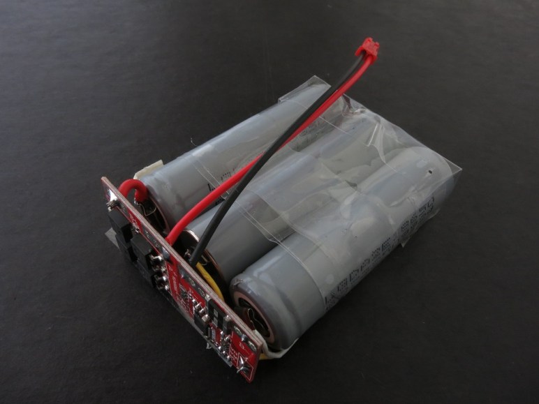
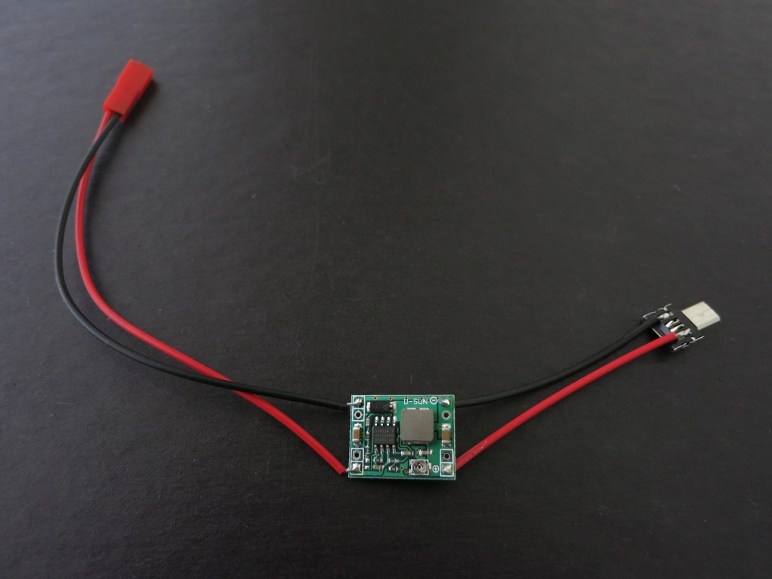
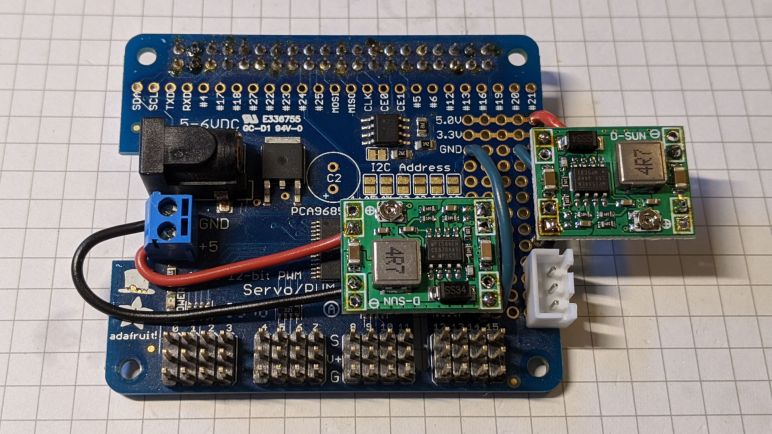
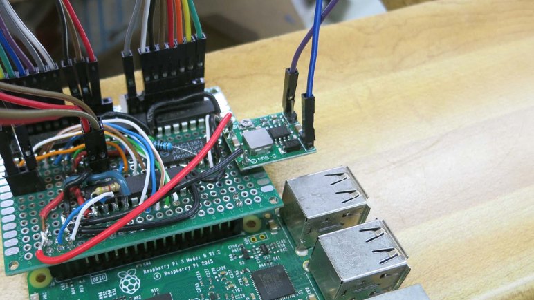
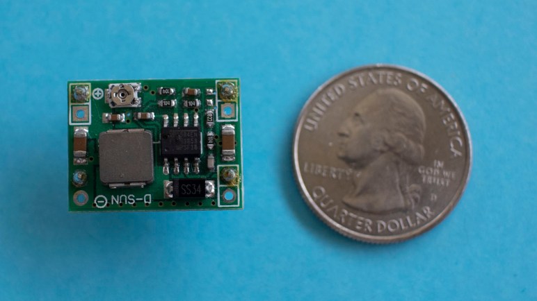
The electronics components I had used to get Micro Sawppy Beta 1 (MSB1) up and running are not representative of my final ambitions. It has a Raspberry Pi 3 with microSD card, the Adafruit PWM/Servo HAT plus two MP1584 buck converters. The upside of this system is simplicity of assembly: thanks to Adafruit, their HAT is close to plug-and-play with a Pi. And if someone uses another power solution, they might not need to solder those MP1584 converters. The servos, for example, could have been powered by a 4- or 5-pack of AA batteries.

The downside is that a remote-control toy rover is really only using a tiny fraction of the capabilities of this system, and these tasks can be done with something simpler and less expensive. For Sawppy V1 I wanted to leave headroom for explorations into autonomy, but it’s been a lot of fun even without that. So I’m OK with downsizing for a micro Sawppy as long as there’s an upgrade path. Whether it be Raspberry Pi, Ardupilot, or some other advanced controller. I still want to make micro Sawppy more affordable, but it’ll be a balance between low cost against ease of assembly.

For wiring, I followed ExoMy’s lead and designed in a lot of wiring channels in the suspension arms, trying to keep wires tidy and out of sight all the way until they pass through narrow channels into the body. Not all of these efforts worked. Some channels were too narrow, making installation impossible. Some channels were too wide, and wires fell out. This was disappointing, but also completely expected. I’m learning how to design wire management channels, I wouldn’t get it all right the first time.

But these intricate pathways had another impact: these micro servos are built with approximately 25cm of wire (plus or minus a few centimeters) which would have been long enough for a little rover whose overall length is about the same. However, now that they have to wind their way back and forth inside suspension components, 25cm is no longer enough.

I had a similar problem with Sawppy V1, where the wires that came with LX-16A serial bus servos were not long enough for a rover. I cut those wires apart and spliced them into a custom wiring harness, but I’d like to avoid that kind of electrical work for building a little Sawppy. Fortunately, unlike LX-16As, micro servos use commodity remote control hobby servo plugs. Which means I could use commodity servo extension cables. (*) And no wire cutting or soldering iron would be required to make MSB1 wires fit inside its suspension geometry.


(*) Disclosure: As an Amazon Associate I earn from qualifying purchases.

Micro Sawppy Beta 1 Electronics

The past several posts have described various aspects of Micro Sawppy Beta 1 (MSB1) that are explorations of new ideas for a little rover. Since there were already many new ideas piled onto the little guy, I decided the control electronics and software should step back and reuse known quantities. Even though I don’t intend this to be the final approach, I wanted to reuse existing components here just to keep things from going too wild and confused if the little rover should encounter problems.

Hence the onboard electronics of MSB1 is very close to those used on Sawppy, which was in turn adapted from code written for SGVHAK Rover. Not from the official JPL Open Source Rover instructions, but the hack I hastily slammed together for its world premier at Southern California Linux Expo. Back then we faced the problem of a broken steering gearbox a week ahead of the event, and it would take over a week for replacements to arrive. So while Emily hacked up a way for a full-sized RC servo to handle steering, I hacked up the rover software to add option to control a servo via what I had on hand: the Adafruit PWM/Servo HAT.

Years later, I still have that same HAT on hand and now I have a rover full of micro servos. Putting them together was an obvious thing to try. My software for that servo steering hack turned out to be very easy to adapt for continuous rotation servos powering the wheels. (Only a single bug had to be fixed.)

There was another happy accident: since the SGVHAK rover software already had software provisions for steering trim, it was easy to use that for throttle trim as well. This was useful to compensate for the fact that the converted continuous rotation servos in the six wheels aren’t necessarily centered like they theoretically were. Resistors with identical markings don’t actually offer perfectly equal resistance, and the control circuit of a cheap micro servo isn’t very good about precise voltage measurements anyway. If I didn’t have this software throttle trim control, it might have been much more difficult to get MSB1 up and running.

For power supply I had a small 2-cell Lithium Polymer battery on hand, previously seen on these pages in exploration of a thrift store Neato. Dropping its voltage (8.4V when fully charged) down to something that wouldn’t fry the micro servos was the job of MP1584 buck converters. I had discovered these worked well for powering a Raspberry Pi and one of them is again enlisted into that role. In order to reduce the chances of a power sag causing the Raspberry Pi to reset, I added a second buck converter to give the micro servos an independent power plane. Both buck converters are soldered onto the little prototyping area Adafruit provided on their HAT. Once I had the electronics circuit stack assembled, I could start wiring up all the components.

Glow Flow Power Regulator

Early on in this project I took a brief look at power requirements for a LED strip with 300 modules. I knew my project would not require maximum power but I didn’t know exactly how much until I got further in the project. Now that I’ve measured actual power consumption with it up and running, it’s time to put a new solution together.

The first and most important thing is safety, so I will have a fuse which is commonly neglected in one-off hobbyist projects. I’ll be using batteries which are rated to supply up to 150A. Nothing in Glow Flow can withstand that power in the event of a problem or a mistake. If that should happen, something will blow, might as well be a fuse whose job it is to do so.

The second thing is the regulator module. I have MP1584 modules (*) that can deliver 2A and peak of 3A, and I have XL4015E1 modules (*) that could deliver peaks of 5A. I know Glow Flow at full brightness will demand at least 5A, with peaks of power draw beyond that when responding to sound stimulus. So the plan is to use two XL4015E1 modules, one for each half of the LED strip.

Glow Flow power module installed

And finally, the convenience of a power switch so I would not have to disconnect and reconnect the battery all the time. All components were placed on a single tray that clips to the inside of Glow Flow cylinder. Leaving plenty of room for a second identical set of battery + power regulator board.

If I had a dual-pole switch I would use one to control my two parallel power supplies. But in my parts collection of compact power switches, I only had single-pole single-throw switches. So Glow Flow will have a switch for each of its two electrically independent power systems. Flipping two switches every time is not ideal, but not the end of the world. It’s only a slight annoyance for the capacity to finally run Glow Flow at full power.


(*) Disclosure: As an Amazon Associate I earn from qualifying purchases.

Power Consideration for Pixelblaze LED Project

I now have a SK9822 300-LED strip up and running under command of a Pixelblaze, and since I configured the Pixelblaze to run the strip at 10% of maximum brightness, I was able to run everything on a USB power bank. This is fine for a quick test, but we should have a better understanding of power requirements for what lies ahead.

The standard rule-of-thumb for LED power budget has been 20mA per LED, and this appears to still hold true for RGB modules like the SK9822. With three LEDs per module, the popular recommendation is to budget a maximum of 3 * 20mA = 60mA per module. I thought the integrated control chip would add to this power requirement but I found no mention of such. With a 5 meter strip of 60 modules per meter, for a total of 5 * 60 = 300 modules, my strip may draw up to a maximum of 300 * 60 mA = 18,000 mA or 18 amps. Running at 5 volts, that is 5 * 18 = 90 Watts of power.

Yikes.

The good news is that, for these types of LED strips, the task of supplying power can be easily parallelized. While they must share a common ground and clock+data lines must run through them all, the voltage supply lines may be separated. So I can, for example, cut the voltage supply line every 50 LED modules and put a power supply on just that segment. 50 * 60 mA = 3,000 mA or 3 amps, which matches the maximum rating for the MP1584 chip I have been using to power my Raspberry Pi projects. I’d just need six of them in parallel to run this strip. I also recently found voltage converters built on the XL4015E1 chip (*), which can deliver up to 5 amps. This would allow driving the strip at max power with fewer modules in parallel.

These are all considerations to keep in mind as the project progresses, but those are not necessarily what will end up in the final product. Mainly because those numbers are worst case scenarios with every module illuminated at maximum brightness, and that’s boring and not flashy at all. In reality I expect to end with only some fraction of LEDs illuminated, and only at a fraction of their maximum power.

So that covers the LEDs, but how much power does a Pixelblaze consume? Since V3 is still under development, precise specifications are not yet available. But it is built around a ESP32 module and I could research from that side. According to this forum thread, ESP32 power consumption is fairly low at roughly 100mA. However, it will occasionally spikes up to as much as 0.6A for brief periods of time. In a LED project with hundreds to thousands of modules, a Pixelblaze’s power consumption is a negligible rounding error.

In the immediate future, I’ll proceed with the project running the strip at 10% brightness and only fraction of 300 modules illuminated. This will allow me to continue using my USB power bank to iterate on ideas and postpone finalizing power supply requirements until there’s a better idea of what the LEDs will do. And an important part of that will be deciding their layout.


(*) Disclosure: As an Amazon Associate I earn from qualifying purchases.

Death Clock Project Priorities

A project that started with exploration of VFD (vacuum fluorescent display) has evolved into a fun little project the Death Clock. Emily has an aesthetic in mind for its external enclosure and I’m fully on board with it. What’s inside the box will be dictated by the priorities we’ve agreed on. The overriding theme is focus: we’ve spent a lot of time and effort getting this far, let’s focus on putting it in use and not get distracted.

For the power system, we will use parts from the original device as we’ve done in our experiments so far. This means the original transformer, rectifier module, and several capacitors. There was the temptation to turn this into a battery-powered contraption for better portability and easier show-and-telling, but that’s a distraction today. We can tackle battery power for a future VFD project.

For the control system, we will use the exploratory control board we’ve rigged up. It is a simple circuit with an 8-bit PIC driving three ULN2003A Darlington arrays. Plus a 3-to-8 bit decoder to help with grid control. We started looking at the Microchip HV5812, a control chip designed specifically for driving VFDs, but that’s a distraction today. We can consider that chip for a future VFD project.

And finally, staying with the theme meant the simple software running on the PIC will remain as-is. I had considered adding the capability to control brightness of individual segments: fade effects are rarely seen in old VFD screens and I thought it would be a fun differentiator between old and new. But again that would be a distraction now and I can pursue it later. Potentially in conjunction with Microchip HV5812 above.

Keeping it simple and avoid feature creep. That’s the key to finishing projects instead of letting them drag on forever.

New MP1584 Regulator Consolidates VFD Project Power Supply

Driving a vacuum fluorescent display (VFD) requires multiple power planes: we needed 2.5V AC for the filament, 30V DC for grids and segments, and 5V DC for a voltage bias between filament and grid/segment as well as driving all electronic logic. In our first test, these three power planes came from three different sources, for an unwieldy mess of three power plugs going to three transformers feeding into our circuit.

While we were working on debugging our control system logic, we also worked on consolidating the power supplies. From the start our 2.5V AC came from a AC transformer that was extracted from the same device we salvaged our VFD from, so we knew it was capable of supplying all the other power planes as well.

Using the same transformer to provide our 30V DC was relatively straightforward, but we had trouble with our 5V DC plane that took some head-scratching. We eventually determined the 5V DC plane couldn’t supply enough power to all the components on the plane because we had our priorities backwards: the highest amperage draw device (the Raspberry Pi 3) was furthest from our 5V voltage regulator when it should have been the closest. Our 5V power sagged to a little over 4V when our Pi was desperately trying to suck enough power through our convoluted nest of wires.

Unfortunately, while trying to move our 5V supply closer to the Pi, we made a wiring error and destroyed the regulator. Oops! Fortunately, these MP1584 modules were very inexpensive and it wasn’t a big deal to bring in a replacement. We just had to wait for a follow-up SGVHAK work session. [Emily] found enough room on our prototype PCB to fasten the regulator with a few soldered header pins so the module doesn’t have to dangle on wires. In hindsight we would have rearranged our layout to make sure there’s room for this regulator, but this is why we build prototypes.

Now our regulated 5V DC supply is first connected to the header pins that supply power to our Raspberry Pi, and from there to the PIC, before finally putting a voltage bias on our filament. This makes far more sense than the other way around, and gave us an electrically reliable system all fed from a single transformer.

Casualty In Debugging 5V Supply for Prototype VFD Driver

Once we had functionality of our prototype VFD driver figured out, we turned our attention to the other problem that cropped up earlier in our initial integration with the original power supply transformer: our 5V rail could support the PIC microcontroller and associated chips, plus putting a voltage bias on the filament. But when put a Raspberry Pi on the circuit, our 5V sagged low enough to put our Pi into a power brown-out reset loop.

Since the MP1584 voltage regulator we used has proven capable of powering a Pi in the past, this was puzzling. So we started quantifying our system starting with measuring the amperage draw of our 5V circuit. It was well within the 3A maximum draw supported by the regulator, so our next thought was a dirty output wave. Putting the output on an oscilloscope, the 5V line looked pretty clean so that was not the explanation.

The next experiment was to isolate the 5V supply chain. Instead of supplying the MP1584 voltage regulator with power from the rectified output of a transformer rail, we’re going to use a two-cell lithium polymer battery. If this worked, we’ll know the problem is upstream in the transformer or rectifier. If it doesn’t, we’ll know the problem is the regulator or further downstream.

Unfortunately the experiment failed due to a wiring error, which destroyed the MP1584 voltage regulator. The title picture shows the entire regulator module with a U.S. quarter dollar coin for scale.

And here’s a close-up of the dead MP1584 chip. The glossy blob in the upper left is plastic that has melted and resolidified. The bump in the middle was a tiny volcano where smoke pushed up through the casing and escaped.

MP1584EN chip with melted hole

Looking on the bright side, we are no longer suspicious of the MP1584 chip’s functionality. We now know for sure it doesn’t work!

Debugging continued with help of a benchtop power supply delivering 5V. Probing with a volt meter through the circuit, and seeing voltage drop along the supply path, we decided our problem wasn’t any single wiring errors in the circuit. We just had too many thin wires and connectors involved in the 5V supply path. We had put our Raspberry Pi at the end of the chain of 5V parts, and it couldn’t draw enough power to run. Not because of any single large obstacle but because of the cumulative effect of lots of little obstacles.

To test this hypothesis, we reversed the chain so our 5V supply entered the system at the Pi then propagated to the rest of the circuit. With this change — and no other change in the circuit — everything started working. This is a valuable lesson to a software person who is used to thinking in terms of digital logic: It’s easy to think 5V rail is 5V as long as there are wires connecting them. This simplification creates a blind spot: the real world is analog and our 5V rail will degrade to a 4V rail when too-thin wires are used!

With that problem solved, we can now start playing with VFD patterns. See what works and see what doesn’t.


Salvaged VFD Power Supply And Debugging

Our first system integration test of a salvaged vacuum fluorescent display (VFD) and our prototype driver PCB was a success. At least going by our initial target of having our VFD segments illuminated and cycling through a test pattern to verify things are not stuck always on or off.

Once we had that basic level of functionality, [Emily] started working on the power supply side of the system. We have an original transformer salvaged from the same device which outputs multiple AC voltages. The first is a 2.5V AC line we could use directly on VFD filament. After that, Emily salvaged a few more components to deliver the ~30V DC we need for control grid and segments, and the ~24V DC we fed into a MP1584 buck converter to get 5V DC for filament bias and micro controller logic power.

VFD on transformer

We’re very close to a complete power solution for a VFD project, but not quite there yet. When we added a Raspberry Pi 3 to the mix, its power demand was too high for this system to handle. Power sagged to 4.2V and the Pi entered a power brown-out reset loop. We’re not sure what’s wrong with this setup yet, but in the meantime we connected an alternate 5V DC power source to look at how the rest of the system behaves.

This allowed us to see a problem in our prototype driver board. I had a new test pattern generated with the help of my tool created in Google Sheets, but the test program did not display as I expected. After some time sending various diagnostic patterns to the VFD, we figured out the key to the situation is segment H.

NEC VSL0010-A VFD Annotated

Whenever segment H is illuminated, everything else functioned as expected. But if segment H is dark, segments A-G are all dark regardless of commanded pattern. Segment I and J are unaffected.

Once this was determined, we ran a test pattern where H is commanded to be dark and everything else should illuminate. The test pattern is the same for every segment, so the circuit would be at a steady state for us to probe with a meter as the PIC cycled through segments.

Using segment A as an example, we probed to verify its output pin from PIC (RC0) is low as expected. We then traced that signal to the ULN2003, whose corresponding input pin is low as expected. With input low, the corresponding ULN2003 output pin should not be tied to ground. Which means we expect VFD pin for segment A to be sitting at near 30V DC due to a pull-up resistor.

This is where we went off script, for VFD pin A has been pulled low. Unplugging the wire between ULN2003 and VFD allowed the segment to illuminate. This narrows down the scope of our problem: it has something to do with that ULN2003 chip, but we ran out of time for tonight’s SGVHAK session before we could narrow it down any further.

To be continued!

Window Shopping BeagleBone Blue

Sawppy was a great ice breaker as I roamed through the expo hall of SCaLE 17x. It was certainly the right audience to appreciate such a project, even though there were few companies with products directly relevant to a hobbyist Mars rover. One notable exception, however is the BeagleBoard Foundation booth. As Sawppy drove by, the reception was: “Is that a Raspberry Pi? Yes it is. That should be a BeagleBone Blue!”

Beaglebone Blue 1600
BeagleBone Blue picture from Make.

With this prompt, I looked into BBBlue in more detail. At $80 it is significantly more expensive than a bare Raspberry Pi, but it incorporates a lot of robotics-related features that a Pi would require several HATs to reach parity.

All BeagleBoards offer a few advantages over a Raspberry Pi, which the BBBlue inherits:

  • Integrated flash storage, Pi requires a separate microSD card.
  • Onboard LEDs for diagnosis information.
  • Onboard buttons for user interaction – including a power button! It’s always personally grated me a Raspberry Pi has no graceful shutdown button.

Above and beyond standard BeagleBoards, the Blue adds:

  • A voltage regulator, which I know well is an extra component on a Pi.
  • On top of that, BBBlue can also handle charging a 2S LiPo battery! Being able to leave the battery inside a robot would be a huge convenience. And people who don’t own smart battery chargers wouldn’t need to buy one if all they do is use their battery with a BBBlue.
  • 8 PWM headers for RC-style servo motors.
  • 4 H-bridge to control 4 DC motors.
  • 4 Quadrature encoder inputs to know what those motors are up to.
  • 9-axis IMU (XYZ accelaration + XYZ rotation)
  • Barometer

Sadly, a BBBlue is not a great fit for Sawppy because it uses serial bus servos making all the hardware control features (8 PWM header, 4 motor control, 4 quadrature input) redundant. But I can definitely think of a few projects that would make good use of a BeagleBone Blue. It is promising enough for me to order one to play with.

Xbox 360 Kinect Needs A Substitute Rover

It was pretty cool to see RTAB-Map build a 3D map of its environment using data generated by my hands waving a Xbox 360 Kinect around. However, that isn’t very representative of rover operation. When I wave it around manually, motions are mostly pan and tilt but not much translation. The optical flow of video feed from a rover traveling along the ground would be mostly dominated by forward travel, occasional panning as the vehicle turns, and limited tilt. So the next experiment is to put the Kinect on a rover to see how it acts.

This is analogous to what we did at SGVTech when I first brought in the LIDAR from a Neato vacuum: we placed on top of SGVHAK Rover and drove it around the shop to see what it sees. Unfortunately, the SGVHAK Rover is currently in the middle of an upgrade and disassembled on a workbench. We’ll need something else to stand in for a rover chassis. Behold, the substitute rover:

kinect with office chair simulating rover

Yes, that is a Xbox 360 Kinect sensor bar taped on top of an office chair. The laptop talking to the Kinect can sit on the chair easily enough, but the separate 12V power supply took a bit more work. I had two identical two-cell lithium battery packs. Wiring those two ~7.4V volt packs in series gave me ~14.8 volts, which fed into a voltage regulator bringing it down to 12V for the Kinect. The whole battery power contraption is visible in this picture taped to the laptop’s wrist rest next to the trackpad.

This gave us a wheeled platform for linear and rotational motion along the ground while keeping the Kinect at a constant height. This is more representative of the type of motion it will see mounted on a rover. Wheeling the chair around the shop, we would see the visual odometer performance is impressive, traveling in a line for about three meters resulted in only a few centimeters of error between its internal representation and reality.

We found this by turning the chair around to let the Kinect see where it came from and compare the newly plotted dots against those it plotted three meters ago. But this raised a new question: was it reasonable to expect that RTAB-Map algorithm match the new dots against the old? Using distance data to correct for odometer drift was one thing Phoebe could do in GMapping. I had hoped RTAB-Map would use new observations to correct for its own visual odometry drift. But instead, it started plotting features a few centimeters off from their original position, creating a “ghost” in point cloud data. Maybe I’m using RTAB-Map wrong somewhere… this is worrisome behavior that needs to be understood.

Simple Base for Neato Vacuum LIDAR

Since it was bought off eBay, there was an obvious question mark associated with the laser scanner salvaged from a Neato robot vacuum. But, following instructions on ROS Wiki for a Neato XV-11 scanner, results of preliminary tests look very promising. Before proceeding to further tests, though, I need to do something about how awkward the whole thing is.

The most obvious problem are the two dangling wires – one to supply motor power and one to power and communicate with the laser assembly. I’ve done the usual diligence to reduce risk of electrical shorts, but leaving these wires waving in the open will inevitably catch on something and break wires. The less obvious problem is the fact this assembly does not have a flat bottom, the rotation motor juts out beyond the remainder of the assembly preventing the assembly from sitting nicely on a flat surface.

So before proceeding further, a simple base is designed and 3D-printed, using the same four mounting holes on the laser platform designed to bolt it into its robot vacuum chassis. The first draft is nothing fancy – a caliper was used to measure relative distance between holes. Each mounting hole will match up to a post, whose height is dictated by thickness of rotation motor. A 5mm tall base connects all four posts. This simple file is a public document on Onshape if anyone else needs it.

Each dangling wire has an associated circuit board – the motor power wire has a voltage regulator module, and the laser wire has a 3.3V capable USB to serial bridge (*). Keeping this first draft simple, circuit boards were just held on by double-sided tape. And it’s a good thing there wasn’t much expectation for the rough draft as even the 3D printer had a few extrusion problems during the print. But it’s OK to be rough for now. Once we verify the laser scanner actually works for robot project purposes, we’ll put time into a nicer mount.

Simple Neato LDS base
Bottom view of everything installed on simple 3D printed base.


(*) Disclosure: As an Amazon Associate I earn from qualifying purchases.

Neato Vacuum Laser Scanner Works in RViz

Scanner Motor Spins
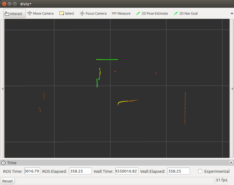
I bought a laser scanner salvaged from a Neato robot vacuum off eBay. The promised delivery date is mid next week but the device showed up far earlier than anticipated. Which motivated me to drop other projects and check out the new toy immediately.

The first test is to verify the rotation motor works. According to instructions, it demands 3.0 volts which I dialed up via my bench power supply. Happily, the scanner turns. After this basic verification, I took one of the adjustable voltage regulators I bought to power a Raspberry Pi and dialed it down to an output of 3.0 volts. Since the connectors have a 2mm pitch, my bag of 4-pin JST-XH connectors could be persuaded to fit. It even looks like the proper connector type, though the motor connector only uses two pins out of four.

The instructions also had data pinout, making it straightforward to solder up an adapter to go between it and a 3.3V capable USB serial adapter. This particular adapter (*) claims to supply 3.3V between 100-200mA. Since the instruction said the peak power draw is around 120mA, it should be OK to power the laser directly off this particular USB serial adapter.

Scanner Power and Data

With physical connection complete, it’s time to move on to the software side. This particular XV-11 ROS node is available in both binary and source code form. I chose to clone the Github source code because I have ambition to go in and read the source code later. The source code compiled cleanly and RViz, the data visualizer for ROS data, was able to parse laser data successfully.

That was an amazingly smooth and trouble-free project. I’m encouraged by the progress so far. I hope we could incorporate this into a robot and, if it proves successful, I anticipate buying more of these laser sensors off eBay in the future.


(*) Disclosure: As an Amazon Associate I earn from qualifying purchases.

Distributing Power Inside Sawppy the Rover

Now that Sawppy has a big battery pack sticking out the back, the next task is to think about how to distribute that power to internal components. This is not yet a big problem in Sawppy’s current configuration because we only have two things right now: the Raspberry Pi and the serial bus servo controller. But since Sawppy has ambition to grow in sophistication, it’s worth thinking about the problem while it’s still easy.

With two components, Sawppy already has two different voltage level requirements. The Raspberry Pi 3 requires regulated 5 volts up to 2.5 amps though fortunately that’s a problem with a known solution. The serial bus servos may draw up to 1 amp each. With ten of them on board, the potential maximum draw would exceed the capability of the voltage regulator used for the Pi. Fortunately the servos are OK with direct 2-cell lithium cell power so there’s no need to find a beefy voltage regulator.

One solution for rover power is to create a master power supply module that can regulate and deliver power required by each component. But at this point in Sawppy’s evolution, it’s too early to know what components never mind what power they want. It’s better to go with a distributed system where raw battery power is sent out and each endpoint is responsible for its own power regulation. This will mean lots of duplication, but it also offers freedom to swap things in and out for experimentation.

For the moment, that means the existing solution for Raspberry Pi will be used. That solves the electrical problem but physical robustness leaves something to be desired. We can’t leave wires dangling by their solder joints!

Flappy Pi Power

A 3D-printed enclosure was designed to hold both the step-down voltage converter and the micro-USB plug used to interface with the Raspberry Pi. They are now connected by a short segment of rigid wire, eliminating movement and a potential point of failure. Power input wires for the voltage converter now have a little bit of help against physical forces from the enclosure. It’s not full and proper strain relief but it’s a start.

Converter Enclosure - open

The two halves of the enclosure are held with zip-ties. Again, not a full and proper solution but much better than dangling wires and bare circuit boards. It’ll be good enough while Sawppy evolves.

Converter Enclosure - closed

A 3D-Printed Enclosure to Take My LED Project On The Go

For the Connect Week event put on by Innovate Pasadena, the Hackaday LA group is hosting the “Bring-A-Hack” event where attendees are encouraged to bring projects (in any stage of completion) for show and discussion. Since I’ve been building my LTC-4627JR driver board as a learning project, I wanted to bring it in for show-and-tell.

Now I could just bring the assembled circuit board and pass it around as an inert object, but what fun would that be? I wanted to bring in something that shows it doing something, and provide some way for people to interact with the whole contraption. Looking at my parts on hand, it seemed easiest to rebuild my thermometer test project. I can have a simple Python program run on the Raspberry Pi, reading temperature from the Tux-Lab Si7021 breakout board, and sending it out to my display. That makes 3 circuit boards, plus they’ll need portable power. I will enlist my Amazon purchases: the 3-cell lithium ion battery pack protected by a S-8254A IC, and the MP1584 buck converter to translate the battery pack’s power into Raspberry Pi friendly voltage.

They present a logistics challenge. There are many parts and while it’s fine to just connect them with wires on my work table, it’s too unwieldy to carry on the Gold Line to Pasadena. I’m going to need some kind of enclosure to carry the whole thing.

To Fusion 360 we go! I just needed a simple enclosure so it was pretty fast to draw up. The bottom tray is for power: it holds the battery cells, their protection board, and the buck converter to 5 volt output. The upper tray holds the Raspberry Pi. The lid of the tray holds my custom LED circuit board, and a few clamps holds it all together. The clamps should be easily removable so I could disassemble the box to show people what’s inside.

ShowandTellBox

I had originally intended to mount the Si7021 breakout board as well, but ended up deciding it would be more fun to have it dangling out for people to play with it. Here are the layers without the clamps, so they can be taken apart and show off the insides.

IMG_5273

And here’s the “travel configuration”, with clamps holding the pieces together.

IMG_5274

This setup worked well. I was able to carry it in my backpack without worrying about tangling up or shorting out wires. Once I arrived, the project was fairly well received and lots of people had fun playing with the thermometer.

Portable External Monitor v3 + Raspberry Pi

The work for portable external monitor (version 3) is winding down and now it’s time for it to get to work. First up: help configure a Raspberry Pi to run the ARM port for ROS Kinetic.

PEMv3vitPi

This is the culmination of several different projects documented on this blog. Most obvious is the portable external monitor project. Which incorporated LED light design from the edge light investigation project. The 12 volt power from the LCD panel driver board is tapped to power the Raspberry Pi, stepped down to 5 volts by the MP1584 voltage step-down converter recently purchased on Amazon. The Raspberry Pi is housed in the 3D-printed enclosure that was one of my first projects in Onshape.

And on the software side, I’m just getting started on learning the Robot Operating System. This specific configuration will help me learn how to set up and run a ROS network across multiple nodes, one being my desktop PC and the other this Raspberry Pi.

Many projects, combined to become whole new projects!

Building a Lithium Ion Battery Pack with S-8254A Protection IC

Encouraged by my earlier success buying somebody’s implementation of an IC reference design off Amazon, I went looking for more. The previous project used a MP1584 chip to regulate the variable voltage of a battery to a constant level for a Raspberry Pi 3. Now I want to improve upon the battery side.

The battery pack had three 18650-sized lithium-ion battery cells in series. These cells were salvaged from an old Dell laptop’s power pack. Since they were ten years old, there’s a bit of a question mark hovering over them. A battery pack that simply wires them in series risks over-charging or over-discharging the weakest cell. This abuse of lithium-ion cells usually ends in a fire.

I searched for a battery management circuit board to help me avoid setting my projects on fire. I settled on this item (*) which is built around the Seiko Instruments’ S-8254A IC. This circuit board will monitor individual cells. If any of the voltage levels exceed safe limits for lithium-ion cells during either charging of discharging, the chip will disconnect the whole pack.

Once everything was connected according to instructions, I have a battery pack that I can use with much higher confidence.


Using my Astro-Flight power meter, I put this battery pack through a full charge and discharge cycle. Something I was squeamish to do before the battery protection board. Upon completion of the cycle, the power meter counted 1.65 amp-hours. The text printed on the cells say LGDA2E18650, which had a nominal 2.25 amp-hour capacity when new. Ten years old and 73% of nominal capacity is not bad, and perfectly usable for a wide range of future projects.


(*) Disclosure: As an Amazon Associate I earn from qualifying purchases.

Powering the Raspberry Pi 3 With MP1584 Voltage Step-Down Converter

The Raspberry Pi 3 is a very impressive piece of hardware for the price, but it has its flaws. One challenge is supplying power to a Pi 3. Like all the Pi boards, power is supplied via a standard micro USB plug. This implies the Pi only needs USB level power with its specified maximum of 0.5 amp @ 5 volts = 2.5 watts. In reality, this USB port is abused beyond the specified range. The Raspberry Pi foundation recommends the power supply for a Pi 3 should supply up to 2.5 amp @ 5 volt = 12.5 watts. Five times the USB specification maximum.

None of the USB power sources I already had could handle this workload. I originally had ideas about running a Pi 3 off of a portable USB charger, but that failed under the vastly greater power draw. I went looking online for solutions.

I needed an efficient DC to DC voltage regulator that can handle the maximum power draw of a Raspberry Pi 3 without consuming a lot of power itself. Since the voltage of a battery changes as it drains, the converter needs to handle a range of input voltages while holding the output voltage steady.

The MP1584 chip from Monolithic Power Systems fit the bill, but I didn’t want to deal with a tiny surface mount IC, nor do I have the skill to design the supporting circuit required. Consulting with a few electronics hardware hobbyists, I got the recommendation to take the reference design out of the datasheet and build that.

And then, an even better recommendation: If it’s a popular chip, and its reference design is good enough, somebody would have mass-produced it and put it on Amazon. And indeed, they have (*). A lot of vendors, in fact, from all around the world.

I scrolled through a few of the listings but didn’t really have a good feel on how to judge one vendor against another. So I took the easy way out: I clicked on the “Amazon’s Choice” link to this offering (*).

Once the module arrived, I soldered battery connectors to the input and a micro USB plug to the output. I adjusted the output voltage to 5 volts, and connected everything to power up my Raspberry Pi 3.

So far it has worked very well. The Raspberry Pi 3 stayed running through tasks that demanded extra power, that would previously trigger a low-power brownout with my existing USB power sources. The output voltage held steady as the battery drained.

Functional, inexpensive, and I didn’t even have to deal with surface mount components! This was a win.

[UPDATE: Need more power? I found another regulator module (*), this one advertises a higher capacity of 5 amps. I successfully used it in my LED project “Glow Flow”]


(*) Disclosure: As an Amazon Associate I earn from qualifying purchases.