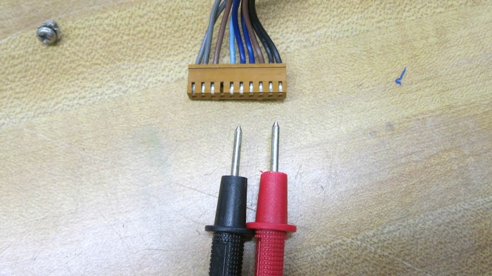
Now that we have a better understanding of how a NEC VSL0010-A vacuum fluorescent display (VFD) works, figuring out its control pinout with the help of an inkjet power supply, we returned to the carcass we salvaged that VFD out of. Now that we knew each pins’ function, we picked those that supplied 2.5V AC for filament power to track. We expect they are least likely to pass through or be shared by other devices. We traced through multiple circuit boards back to the main power transformer output plug. We think it’s the two gray wires on the left side of this picture, but our volt meter probes are too big to reach these visible contact points. And the potential risk of high voltage made us wary of poking bare wires into that connector as we did for the inkjet power supply.
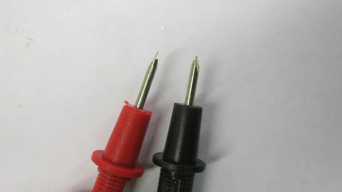
Our solution came as a side benefit of decision made earlier for other reasons. Since we were new to VFD technology, our curiosity-fueled exploratory session was undertaken with an inexpensive Harbor Freight meter instead of the nice Fluke in the shop. Originally the motivation was to reduce risk: we won’t cry if we fry the Harbor Freight meter, but now we see a secondary benefit: With such an expensive device, we also feel free to modify these probes to our project at hand. Off we go to the bench grinder!
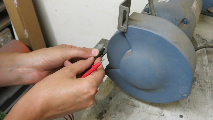
A few taps on the grinding wheel, and we have much slimmer probes that could reach in towards those contacts.
Suitably modified, we could get to work.

We were able to confirm the leftmost pair of wires, with gray insulation, is our 2.5VAC for VFD filament. The full set of output wires from this transformer, listed by color of their insulation, are:
- Gray pair (leftmost in picture): 2.6V AC
- Brown pair (spanning left and right sides): 41V AC
- Dark blue pair: (center in picture) 17.2V AC
- Black pair (rightmost in picture): 26.6V AC
There was also a single light-blue wire adjacent to the pair of dark blue wires. Probing with volt meter indicated it was a center tap between the dark blue pair.

Once determined, we extracted the transformer as a single usable unit: there was a fuse holder and an extra power plug between it and the device’s AC power cord. We’re optimistic this assembly will find a role in whatever project that VFD will eventually end up in. 2.6V AC can warm filament, rectified 26.6V AC should work well for VFD grid and segments. And with proper rectification and filtering, a microcontroller can run off one of these rails. It’ll be more complex than driving a LED display unit, but it’ll be worth it for that distinctive VFD glow.
