Linear CCD Sensor And Other Curiosities In A Fax Machine

For SGVHAK’s regular first Thursday of the month meeting for June, Emily brought in an old fax machine abandoned by the side of the road.

The plastic enclosure yellowing from age is not a surprise, but its heft was: it was far heavier than it looked. Judging by the collection of debris this machine had gathered, it had been left outdoors for some time. It was not a surprise when it failed to power on. Which is fine as we had no use for a fax machine and little interest in fixing it, but we were curious what was inside one of these anachronisms.

Most of this device’s mass came from a single beefy cast aluminum frame inside the machine. Select portions have been machined to precise tolerances. Why was this necessary? Emily hypothesized the robust frame was necessary to hold optical scanning components in precise alignment. The optical path was more complex than we had expected. Illumination came from a wide LED strip sitting under what looks like a glass rod slice lengthwise. It began to emit visible yellow-green light at roughly 15 volts (while drawing less than 200mA) and we cranked it as high as 20 volts (just under 500mA) but no further as we didn’t know the strip’s limits.

That light bounced off a few front surface mirrors before reaching the document, whose reflected light is picked up by yet more mirrors and finally a lens assembly that focused onto a sensor. A web search for TCD102D only found the first page of this device’s data sheet. But it was enough to tell us it was a line of 2048 photodiodes designed specifically for this purpose of scanning a line of a document scrolling past sensor optics.

For the output side of this device, there was a roll of thermal paper and a thermal image print head that worked much like the sensor in reverse: a line that heats a sheet of paper rolling past it to create an image. Digging below them both, we find the mechanical pieces making paper scroll. There was a stepper motor driving rollers for source document, and another stepper motor driving rollers feeding thermal paper for output.

Beyond the two stepper motors, few components had prospect for reuse though some (like the front surface mirrors) were kept for novelty. Unfortunately this disassembly also evicted an insect from its now-demolished home.

The biggest win was a lens assembly that formerly sat in front of the linear CCD. It has the right optical properties to be used as a small macro lens for an equally small cell phone camera. Emily plans to design and 3D print a bracket to hold this lens at the proper location and distance so we should see more close-up shots of small electronics components in the future.

Original NEC VSL0010-A VFD Power Source

Now that we have a better understanding of how a NEC VSL0010-A vacuum fluorescent display (VFD) works, figuring out its control pinout with the help of an inkjet power supply, we returned to the carcass we salvaged that VFD out of. Now that we knew each pins’ function, we picked those that supplied 2.5V AC for filament power to track. We expect they are least likely to pass through or be shared by other devices. We traced through multiple circuit boards back to the main power transformer output plug. We think it’s the two gray wires on the left side of this picture, but our volt meter probes are too big to reach these visible contact points. And the potential risk of high voltage made us wary of poking bare wires into that connector as we did for the inkjet power supply.

NEC VSL0010-A VFD Power Supply - Probes Too Fat

Our solution came as a side benefit of decision made earlier for other reasons. Since we were new to VFD technology, our curiosity-fueled exploratory session was undertaken with an inexpensive Harbor Freight meter instead of the nice Fluke in the shop. Originally the motivation was to reduce risk: we won’t cry if we fry the Harbor Freight meter, but now we see a secondary benefit: With such an expensive device, we also feel free to modify these probes to our project at hand. Off we go to the bench grinder!

NEC VSL0010-A VFD Power Supply - Probes Meet Grinder

A few taps on the grinding wheel, and we have much slimmer probes that could reach in towards those contacts.

NEC VSL0010-A VFD Power Supply - Probes Now Thin

Suitably modified, we could get to work.

NEC VSL0010-A VFD Power Supply - Probes At Work

We were able to confirm the leftmost pair of wires, with gray insulation, is our 2.5VAC for VFD filament. The full set of output wires from this transformer, listed by color of their insulation, are:

  • Gray pair (leftmost in picture): 2.6V AC
  • Brown pair (spanning left and right sides): 41V AC
  • Dark blue pair: (center in picture) 17.2V AC
  • Black pair (rightmost in picture): 26.6V AC

There was also a single light-blue wire adjacent to the pair of dark blue wires. Probing with volt meter indicated it was a center tap between the dark blue pair.

NEC VSL0010-A VFD Power Supply Transformer

Once determined, we extracted the transformer as a single usable unit: there was a fuse holder and an extra power plug between it and the device’s AC power cord. We’re optimistic this assembly will find a role in whatever project that VFD will eventually end up in. 2.6V AC can warm filament, rectified 26.6V AC should work well for VFD grid and segments. And with proper rectification and filtering, a microcontroller can run off one of these rails. It’ll be more complex than driving a LED display unit, but it’ll be worth it for that distinctive VFD glow.

HP Inkjet Printer Power Supply For NEC VSL0010-A VFD

One of the reasons LED has overtaken VFD in electronics is reduced power requirements. Not just in raw wattage of power consumed, but also the varying voltage levels required to drive a VFD. The NEC VSL0010-A VFD whose pinout we just probed ran on 2.5V AC and ~30V DC. In contrast, most LED can run at the same 5V or 3.3V DC power plane as their digital drive logic, vastly simplifying design.

We didn’t have a low voltage AC source handy for probing, so we used 2.5V DC. We expected this to have only cosmetic effects. One side of our VFD will be brighter than the other, since one side will have a filament-to-grid/element voltage difference of 30V but the other will only have 27.5V.

But putting 2.5V DC on the filament occupied our only bench power supply available at the time. What will we use for our 30V DC power source? The answer came from our parts pile of previously disassembled electronics, in this case a retired HP inkjet printer’s power supply module labeled with the number CM751-60190.

HP CM751-60190 AC Power Adapter

According to the label, this module could deliver DC at 32V and 12V. Looking at its three-conductor output plug, it was easy to come to the conclusion we have one wire for ground, one wire for 32V, and one wire for 12V. But that easy conclusion would be wrong. Look closer at the label…

HP CM751-60190 AC Power Adapter pinout

We do indeed have a ground wire in the center, but there is only one power supply wire labelled +32V/+12V. It actually delivers “32 or 12” volts, not “32 and 12” volts. That last pin on the left has an icon. What did that mean? Our hint comes from power output specifications: +32V 1095mA or +12V 170mA. We deduced this meant the icon is a moon, indicating a way to toggle low-power sleep mode where the power supply only delivers 12V * 170mA = 2 watts vs. full 32V * 1095mA = 35 W.

With that hypothesis in hand, it’s time to hook up some wires and test its behavior.

HP CM751-60190 AC Power Adapter test

When “sleep mode” pin is left floating, voltage output is 32VDC. When that pin is grounded, voltage output drops to 12VDC. Since we’re looking for 32VDC to drive our VFD grid and elements, it’s easy enough to leave sleep wire unconnected and solder wires to the remaining two wires to obtain 32V DC for our VFD adventures.

HP CM751-60190 AC Power Adapter new wires

Sleuthing NEC VSL0010-A VFD Control Pinout

Vacuum Fluorescent Display (VFD) technology used to be the dominant form of electronics display. But once LEDs became cheap and bright enough, they’ve displaced VFDs across much of the electronics industry. Now a VFD is associated with vintage technology, and its distinctive glow has become a novelty in and of itself. Our star attraction today served as display for a timer and tuner unit that plugs into the tape handling unit of a Canon VC-10 camera to turn it into a VCR. A VFD is very age-appropriate for a device that tunes into now-obsolete NTSC video broadcast for recording to now-obsolete VHS magnetic tape.

Obviously, in this age of on-demand internet streaming video, there’s little point in bringing the whole system back to life. But the VFD appears to be in good shape, so in pursuit of that VFD glow, salvage operation began at a SGVHAK meetup.

NEC VSL0010-A VFD Before

We have the luxury of probing it while running, aided by the fact we can see much of its implementation inside the vacuum chamber through clear glass. The far right and left pins are visibly connected to filament wires, probing those pins saw approximately 2.5V AC. We can also see eight grids, each with a visible connection to its corresponding pin. That leaves ten pins to control elements within a grid. Probing the grid and element pins indicate they are being driven by roughly 30V DC. (It was hard to be sure because we didn’t have a constant-on element to probe…. like all VCRs, it was blinking 12:00)

This was enough of a preliminary scouting report for us to proceed with desoldering.

NEC VSL0010-A VFD Unsoldering

Predating RoHS solder that can be finicky, it was quickly freed.

NEC VSL0010-A VFD Freed

Now we can see its back side and, more importantly, its part number which immediately went into a web search on how to control it.

NEC VSL0010-A VFD Rear

The top hit on this query is this StackExchange thread, started by someone who has also salvaged one of these displays and wanted to get it up and running with an Arduino. Sadly the answers were unhelpful and not at all supportive, discouraging the effort with “don’t bother with it”.

We shrugged, undeterred, and continued working to figure it out by ourselves.

NEC VSL0010-A VFD Front

If presented with an unknown VFD in isolation, the biggest unknown would have been what voltage levels to use. But since we have that information from probing earlier, we could proceed with confidence we won’t burn up our VFD. We powered up the filament, then powered up one of the pins visibly connected to a grid and touched each of the remaining ten non-grid pins to see what lights up. For this part of the experiment, we got our 32V DC from the power supply unit of a HP inkjet printer.

We then repeated the ten element probe for each grid, writing down what we’ve found along the way.

NEC VSL0010-A VFD Annotated

We hope to make use of this newfound knowledge in a future project, and we hope this blog post will be found by someone in the future and help them return a VFD to its former glowing glory.

Rover Mr. Blue Now Up And Running On SGVHAK Rover Code

Mr. Blue is alive

While I’m making my way learning how to write proper modules for Robot Operating System, the rest of my SGVHAK compatriots have not been twiddling their thumbs waiting. Just like I went and built Sawppy as my idea of a cool rover project, Dave designed and built Mr. Blue as his idea of a cool rover.

All the blue printed plastic parts (which gave this rover its name) was designed in Dave’s preferred CAD software OpenSCAD. These pieces connect thin wall aluminum tubing that is very strong yet quite affordable. Making this rover a great exploration into a construction method quite different from Sawppy, where I designed 3D-printed plastic components in Onshape CAD and they connected Misumi aluminum extrusion beams.

Mr. Blue also expresses Dave’s ability to design and build electronics circuits. Where my Sawppy used serial bus servos, Dave has custom controller boards driving all the motors. There are two types on board: one drives a DC motor with feedback provided by optical quadrature encoders, the other drives a commodity servo motor but with precise position feedback via high-resolution magnetic encoders. In both cases, they feed into a 3D-printed gearbox for additional mechanical reduction.

Originally, the plan was to get Mr. Blue up and running on ROS, but Dave’s progress at construction was faster than my progress at learning ROS. As an interim solution, I added support for Dave’s motor control boards to my SGVHAK Rover software project. Now we have the same basic software running three rovers built with three different motor systems:

We have quite a rover family going!

Trying To Make Two Good Neato XV Battery Packs From Four Bad Packs

Neato XV battery pack untouched

A Neato robot vacuum in their initial XV series product line is powered by a pair of identical 6-cell NiMH battery packs. When I picked up my XV-21 from a local thrift store it did not power up, a fault which I’ve isolated to its failed battery packs which I’ve since replaced to get the whole system back up and running with help of [Emily]’s loan of Neato charging dock. When I evaluated my battery replacement options earlier, one was to buy new cells and rebuild the pair of packs myself. I rejected that option because new cells actually would have cost more than pre-built replacement packs.

But since then Emily found a second thrift store Neato, a XV-12 with its own failing battery pack. This makes a total of four identical 6-cell NiMH battery packs. What are the chances we have sufficient good-enough NiMH cells in this pile for one set of healthy batteries? It costs nothing but a bit of time, well within the spirit of the kind of projects we tackle at SGVHAK meetups, and so it’s worth a shot.

First, the XV-12 battery packs were trickle charged overnight to get a sense of their capabilities, just like I did for XV-21 batteries earlier. Fortunately, the self-discharge profile looked promising.

Pack A: 7.93V self discharged to 7.64V after a few days.

Pack B: 6.59V self discharged to 5.98V after a few days.

Judging on voltage level alone, pack A is in better shape than pack B. The latter shows signs of having one completely dead cell. They’re certainly in far better shape than XV-21 battery pack. Out of 12 cells, only 1 held itself at ~1.3V after a week. The rest all self-discharged to a level ranging from 0.9V to flat zero after a few days.

So we disassembled pack B and deployed a volt meter to verify there is one cell that could only deliver around 0.1V. This cell was marked with an X and removed from the pack. Since we don’t have a battery spot welder available, we took care to make sure we keep the tabs on this pack.

The only not-dead cell from the XV-21 pack was marked with a check and removed from its pack. And again we took care to keep the battery tabs, this time making sure it stays with the ‘good’ cell.

Neato XV battery pack cell replacement

With the battery tabs intact, it was easy to solder a new pack together.

Neato XV battery pack soldering

A dab of hot glue helps the cobbled-together pack stay intact for installation into vacuum

Neato XV battery pack installed

When we turned on the robot vacuum, it no longer displayed a battery issue error screen, which is a great sign. We then left the robot sitting on its charger for about half an hour, then pressed the big red button to start a vacuum cycle. The vacuum suction motor turned on (Yay!) the brush motor turned on (Yay!) the robot started to move (Yay!) and then it went dark. (Noooo!) When we tried turning it back on, the error screen returned.

Neato XV battery pack still unhappy

Our little cell-swapping experiment did not result in a battery pack capable of running a Neato. It might find a future life powering low drain electronics projects, but it wasn’t enough to run a robot vacuum’s high drain motors. Emily ended up buying new battery packs as well to restore her XV-12 back to running condition.

Examining Neato XV-12 Charging Dock

When [Emily] found her Neato vacuum in a thrift store, it had an advantage over mine in that hers still have the company of its charging dock. This is our first look at a Neato robot vacuum charging dock and a chance to determine how one worked. We wanted to have some idea of what to expect when we put it to work charging newly installed replacement batteries.

Neato charging dock front

The charging dock is designed to sit against a wall. The two metal strips are obviously for supplying power, as they line up with the two metal wires at the back of a Neato vacuum. When the dock is plugged in, a volt meter reports 24V DC between those two plates, top plate positive and bottom plate ground. Each of the plate is mounted on a piece of spring-loaded plastic that allows approximately 3-5mm of horizontal movement. A Neato vacuum can press its wires against these plates to draw power.

Above the plates is a black plastic window, we expect something behind that window to communicate with the Neato so a hungry robot vacuum knows where to go to feed itself. How does it work? We hypothesized there are infrared emitters and receivers behind that panel, functioning like a consumer electronics remote control, to talk to a Neato vacuum.

Neato charging dock back.jpg

Neato charging power adapterThe orange tab on top looked very inviting as a way to open the dock. A bit of fiddling later, the dock was open. It was surprisingly simple inside. There was an AC power supply delivering 24V DC. It has a standard power cable on the input side, which can be routed to exit either side of the dock. This way a user can swap as needed to point towards the nearest power outlet, and possibly swap for a longer standard power cable if necessary to reach an outlet. The output wires of the power supply lead to the two metal plates, and that’s it.

Surprisingly, there’s nothing visible behind the black plastic window. The IR emitters and receivers we expected were absent, as were any circuit boards with components to communicate with the vacuum. So this charger dock location beacon must work passively. Now we’re really interested in finding out more. How does it work?

The black plastic window were held in place with a few clips. They stood between us and knowledge and were quickly dispatched. We were afraid the black plastic might be glued in place, but fortunately that was not the case and it popped off for us to see underneath.

Neato charging dock mystery panel demystified

We see a pattern laid out with two types of surfaces. The white segments are highly reflective much like the stripes on high visibility orange safety vests. The black segments are presumed to provide a contrast against the white parts. We found out earlier that a Neato lidar data stream returns both distance and intensity of reflections it saw. The distance is useful for navigation, but using just distance information the charger would be an unremarkable flat surface. This is where intensity comes into the picture: these surfaces behind the black plastic window will create a distinct pattern in reflection intensity, something a Neato robot vacuum can seek to find its charging dock.

Disassembling this passive system tells us two things:

  1. The engineers are Neato are quite clever
  2. We now know enough to try creating our own charging docks. Userful when we have Neato vacuums found at thrift stores without their charger.

Before we tackle new projects, though, let’s see how a full Neato system works in practice.

AltoEdge Infinity USB Foot Pedal Dates Back Before Windows 7

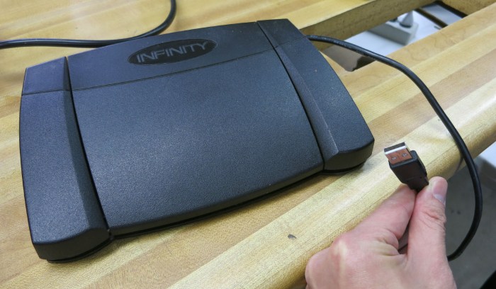
This SGVHAK teardown project came courtesy of an electronics waste bin. A nondescript box with a USB cable, it has three moving parts on top of a heavy base. The center piece takes up majority of width, and two far smaller pieces sitting on either side. Each piece can be pressed down and we can feel a tactile click of a switch. It has a respectable heft and doesn’t look damaged or even worn. It feels rather beefy and unlikely to physically break.

Infinity Foot Pedal IN-USB-2

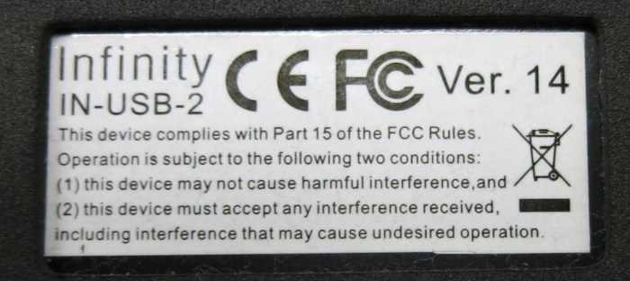
A label on the bottom of the device lets us know it is version 14 of the Infinity IN-USB-2 foot pedal. Which explains its mass and durability: this box was designed to sit under a desk and be stepped on. A box sitting out of sight explained its raised side pedals allowing its user to find them by feel.

Infinity Foot Pedal IN-USB-2 v14 label

A few screws on the bottom held a plate in place, easily removed. We see a few springs for the pedals, and two pieces of metal that gave the device its heft.

Infinity Foot Pedal IN-USB-2 bottom panel removed

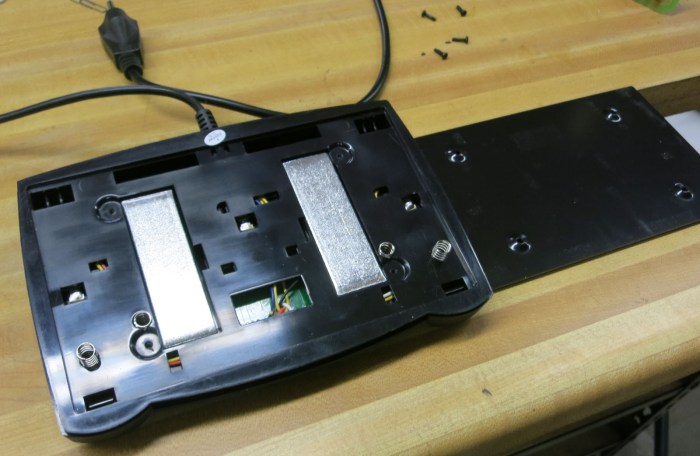
There were a few visible plastic clips holding individual pedals in place, but they were only the first line of defense – unclipping them allowed individual pedal to move a little further but did not release them. There were also a few hinge pins that could be removed, but again it allowed additional movement but did not release.

The two shiny metal weights were held by tenacious stretchy glue. We could pry them up far enough to see they weren’t obviously hiding screws, but we were wary to apply addition force as it threatened to break apart the plastic housing.

Without an obvious way forward for nondestructive disassembly, we decided to pause and reassemble the pedal to see if it can be useful intact before we risk destroying it. My computer was running Ubuntu at the time, which gave us a starting point with the dmesg tool to see what kind of greeting it has to say to my computer.

[ 459.086214] usb 1-4.4.3: new low-speed USB device number 17 using xhci_hcd
[ 459.192673] usb 1-4.4.3: New USB device found, idVendor=05f3, idProduct=00ff
[ 459.192679] usb 1-4.4.3: New USB device strings: Mfr=1, Product=2, SerialNumber=0
[ 459.192683] usb 1-4.4.3: Product: VEC USB Footpedal
[ 459.192687] usb 1-4.4.3: Manufacturer: VEC
[ 459.196360] input: VEC VEC USB Footpedal as /devices/pci0000:00/0000:00:14.0/usb1/1-4/1-4.4/1-4.4.3/1-4.4.3:1.0/0003:05F3:00FF.0012/input/input28
[ 459.196980] hid-generic 0003:05F3:00FF.0012: input,hiddev1,hidraw9: USB HID v1.00 Device [VEC VEC USB Footpedal] on usb-0000:00:14.0-4.4.3/input0

So far everything looks in line with the manufacturer’s name we found earlier. It also tells us the device conforms to USB HID (Universal Serial Bus Human Interface Device) specification. The final line also hinted us to a newly visible device under the path/dev/hidraw9.

$ ls -l /dev/hidraw9
crw------- 1 root root 240, 9 Mar 17 13:32 /dev/hidraw9

This path is owned by root, so further experimentation requires taking ownership of that path to see what we can do with it.

$ sudo chown $USER /dev/hidraw9

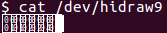
Now we can try treating it as a file with the cat command. Every time we press or release a pedal we get some kind of visual feedback but we don’t understand it.

cat dev hidraw9

We then tried treating it as a serial port using minicom but that didn’t get us much further. It vaguely resembles the garbage that might occur if a baud rate setting is incorrect, but changing baud rate in minicom didn’t do anything. Probably because it’s not a serial port!

Since the device was classified as a USB HID v1.00 Device, the next thought was to try communicating with it via some sort of HID API for developers. But USB HID is not a trivial thing and after a half hour of following and reading links to documentation I was no closer to talking to the pedal in a “proper” way. So I tabled that approach and returned to treating it as a file. It’s pretty trivial using Python’s file APIs to open it up for reading.

>>> hr9 = open('/dev/hidraw9','r')

Reading a few bytes at a time, we figured out the device sends two bytes upon every action. First byte is a bitfield indicating pedal status, and the second is always zero. The leftmost pedal corresponds to the least significant bit 0x1, then center pedal 0x2 and right pedal 0x4. So if both right and center pedals were both pressed, it would give 0x6. Here’s a simple Python loop that reads two bytes at a time and outputs to command line.

>>> while True:
... hr9.read(2)

The output if I press and release the left, then repeat for center and right pedal.

'\x01\x00'
'\x00\x00'
'\x02\x00'
'\x00\x00'
'\x04\x00'
'\x00\x00'

Not every action will trigger data events. There’s a small time window where separate events are collapsed together for a single notification. If I’m quick enough on the press and on release, I can push the right and left pedals simultaneously for a single 0x05 report, then release simultaneously for a 0x00 report, without any intermedia reports of 0x04 or 0x01.

'\x05\x00'
'\x00\x00'

This is a very promising set of experiments indicating that, if it should be necessary, we can write code to make use of this pedal in Linux without digging through all of HID API.

With that knowledge under our belts, experimentation then moved to Windows 10, which immediately recognized it as a USB HID and even shows us the name. However, it doesn’t do much without further help.

VEC USB Footpedal device is ready

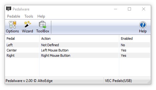
Searching for answers on the web, we learned this device was designed for people transcribing audio recordings into text. The pedals allow them to control sound playback (pause, play, rewind, etc.) without taking their typing hands off the keyboard. I’m sure this is a productivity boon for its target audience, but that wasn’t us. Fortunately, the manufacturer has also released a piece of software call Pedalware which will allow this pedal to be used outside its designed scenario, like emulating keyboard keys or mouse buttons. I thought it sounded interesting enough to try.

And this is where we started getting a hint why this device has been retired… this piece of hardware’s associated software is old. Pedalware’s installer demands Windows 7 or earlier and refused to run under Windows 10.

Pedalware needs Windows 7 or earlier

At this point, Windows 10 backwards compatibility module kicked in and offered the option of running in compatibility mode. I accepted.

Pedalware needs Windows Vista compatibility mode

That was enough to get Pedalware up and running on my Windows 10 computer. Now I can assign an arbitrary keyboard or mouse action to each of three pedals.

Pedalware up and running

This worked fine in everyday web browsing and productivity applications. It is, however, too slow for gaming purposes. The aforementioned time window seen under Linux, which collapsed multiple events into a single event, manifests here as well resulting in foot click actions getting lost in high-speed gaming action.

But that’s fine, the device was never intended to be a gaming peripheral. The real problem comes from its driver software becoming unreliable as a computer goes into low-power standby. When the computer resumes, the pedal doesn’t always come back into action. And once it gets stuck, the only way to get it back is a full reboot.

This was a sign of the times when this device was designed. I remember when many peripherals would not gracefully handle a computer going to sleep, which meant I typically leave my computer running in the Windows XP/Vista/7 days. Computers have gotten more power efficient over these years but it’s still better to put them to sleep. Also, modern USB peripherals are much better about resuming from sleep.

But this pedal does not, and that’s probably why it was retired. Fortunately, my work does not require a predictably functional foot pedal, so I’ll keep it around and try using it on the occasions when it works.
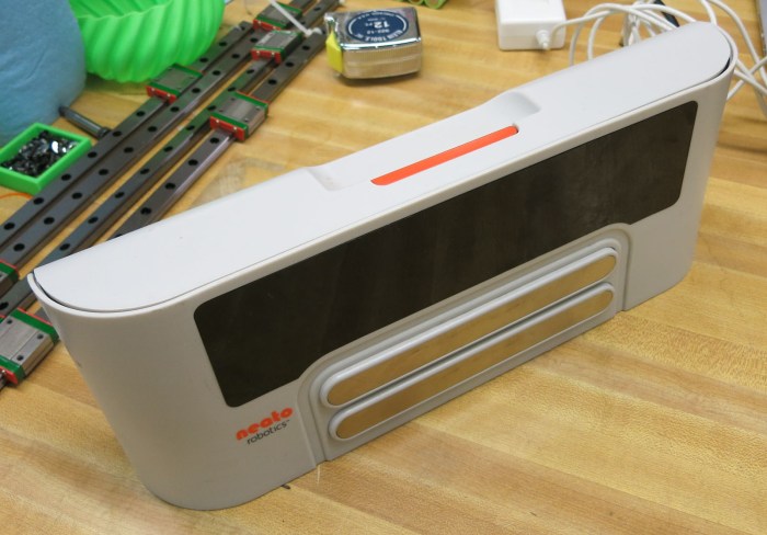
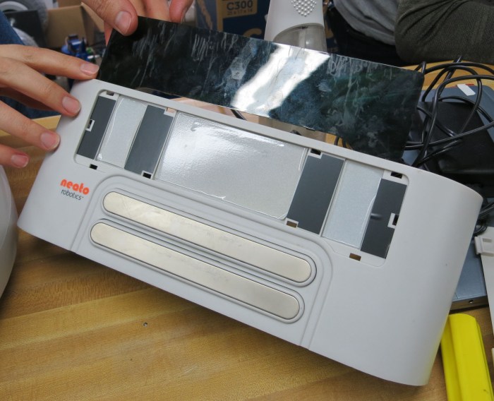
Cree Dimmable LED Bulb Teardown

I brought an old LED light bulb to a SGVHAK meetup for an educational dissection. This bulb has illuminated my front porch for several years, hooked up to a light-sensitive fixture that turns on the bulb when dark, and turn it off when the sun is up. However, when illuminated this bulb has started flickering. At first it was a mild pulse that I didn’t mind very much as I don’t usually need the light myself anyway. But after a while, the blinking started getting annoying and even the bright pulses were too dark for the light to serve its intended purpose. This bulb was retired, and now we take it apart to see what’s inside.

Looking inside the cooling vents, we can see there are two circuit boards mounted at right angles to each other. Obviously there will be LEDs soldered to these boards, with a power supply at its base. Since all the LEDs pulsed together, we expect there to be a power supply failure and hope we might be able to see what component caused the problem.

Here’s the bulb intact, before teardown began.

Cree LED bulb teardown 1 - intact

Here’s the label on the bulb. This was not a bargain basement device, it was a dimmable bulb and it was also designed to be usable in damp environments as the front porch is occasionally exposed to rain. It was also exposed to outdoors wildlife, including some insects who have climbed inside and sadly died there, too.

Cree LED bulb teardown 6 - label

It was nicely sealed with no obvious way to take apart the plastic housing nicely, so out came a beefy cutter and we start cutting from top vents.

Cree LED bulb teardown 2 - first cut

Once the top vents were clipped open, we could perform some literal debugging of our device by pouring the dead carcasses out. They look like honeybees.

Cree LED bulb teardown 3 - pour out the bugs

Aside from debugging, the opened top also lets us see more details inside. Sadly, there were no visible mechanisms for easy release, so cutting continues at waist-level vents.

Cree LED bulb teardown 4 - second tier cut

Once those portions were cut away, we could see more of internals. There were fewer LED surface mount packages than we had expected.

Cree LED bulb teardown 5 - second tier removed

At this point I ran out of convenient places to cut with a hand tool, so cutting moved on to a band saw.

Cree LED bulb teardown 7 - band saw

Once the band saw cut through all around the base of transparent plastic bulb exterior, we were able to free its internals for a closer look. Surprisingly, the circuit boards connect to each other and to the base with tiny spring-loaded connectors rather than a direct soldered joint. One hypothesis is the bulb was not only designed for humid environments, it was designed to sustain vibration as well. Another hypothesis was that humid environments also imply a larger temperature swing, where spring-loaded connectors can accommodate thermal expansion/contraction better than soldered joints.

Cree LED bulb teardown 8 - disassembled

Here is the main board’s topside. Nothing appeared obviously damaged. The big electrolytic capacitor immediately drew our attention, as that is the type of component most likely to fail with age. However, the usual signs were absent. No leaking electrolyte, no bulging of the body, and no breakage in the top. With the help of our multi meter, we could tell the capacitor has neither failed open or failed short. We also measured its capacitance, which won’t be a reliable number as the capacitor is still installed on the board: we’d be measuring capacitance of the capacitor as well as the board it is installed on. But the number was roughly in the ballpark of the rating printed on its side, so it looks clear on all counts.

Cree LED bulb teardown 9 - main board front

Bottom side of the main board showed no such obvious attention-getters. The small light colored surface mount component at the base might be a safety fuse, and it tested OK for continuity.

Cree LED bulb teardown A - main board back

We explore the fewer-than-expected LED modules by trying to power up a single LED using a bench top power supply. At first it stayed dark and we thought maybe the LEDs were at fault instead of the power supply. But then we realised we weren’t giving it enough power: we were surprised it took over 24 volts before a single module would illuminate.

Cree LED bulb teardown B - LED needs 24V

An explanation surfaced once we adjusted camera settings to see individual light sources inside the package: there are actually ten LEDs in each package, in a three + four + three configuration. This explains how it could be so bright with so few surface mounted modules!

Cree LED bulb teardown D - ten LED per package

At this point we’ve verified all the discrete components we understood and could test, we’ve removed dead bug remains that might have caused problems, and we cleaned up all the electrical connectors. Maybe that’s enough to bring this bulb back to life?

Cree LED bulb teardown C - back on 110V AC

Sadly, the answer was no. We hooked it up to AC power and plugged it in: it is still dim and blinky. Obviously we failed to understand how this particular bulb works – the power supply circuitry was far more complex and sophisticated than we had expected. But still, it was fun to look inside a premium (for its day) LED bulb.