
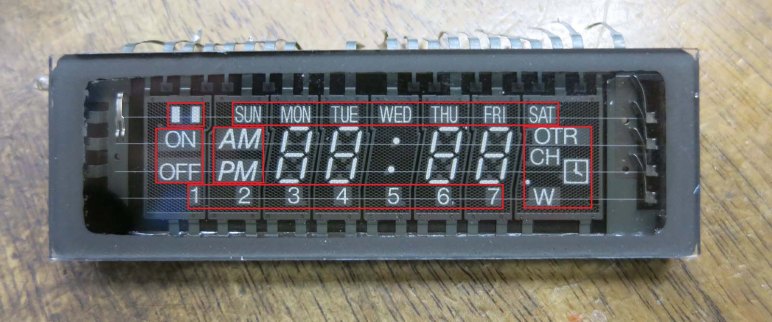
Before I can become a hotshot web developer capable of utilizing any library I come across, I need to build up my skills from small projects. One of the ideas that occurred to me recently was motivated by an appreciation for vacuum fluorescent displays (VFD) as used in a Buick Reatta dashboard.
I’ve played with a small VFD salvaged from an old video cassette machine, but that’s nothing like the panorama we see on a Reatta dashboard. It is not something we’re likely to see ever again. The age of VFDs have long since passed and it’s not practical for an average hobbyist to build their own. The circle of people who consider VFD retro cool is probably not big enough to restart VFD manufacturing. That leaves us with building fakes out of technology we have on hand, and I thought I could quickly prototype my idea using web technologies, and here it is:
There are two parts to this faux VFD.
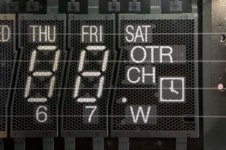
Less obviously visible is the fine hexagonal mesh emulating the control grid I saw when I put my salvaged VFD under a macro lens. I believe it is one of the two electrodes, whether anode or cathode I do not know. But it is a subtle part of a VFD that designers put effort into reducing and masking. Now it is part of the VFD charm and I wanted to replicate it.
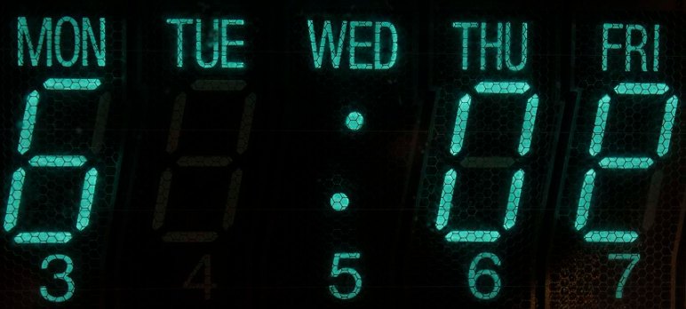
Since it is a pattern built out of many small repeating sections, I thought the best way to recreate this mesh is with a bit of JavaScript code drawing to a <canvas>. Otherwise, I would have to create it in markup and that means a lot of duplication in a massive markup file. The innermost section of the loop draws three lines 60 degrees apart, and the loop iterates across the entire display area. Using code to draw vector graphics (versus tiling a bitmap) make this grid dynamically scalable to different resolutions.

Rendered behind the mesh is the “content” of the VFD, which is just a simple circle in this case. Since this is a large feature likely to be subject to direct editing, I decided to do this in SVG markup. My first attempt didn’t look right: modern screens are far too clear and crisp compared to a VFD. Such clarity is useful to render the fine details of my hexagonal control grid, but not for the VFD phosphors. I looked around online and found a SVG blur filter which was a lot closer to how a VFD would look.
I know the result isn’t perfect and I don’t know if I would end up applying this experiment to a future project, but I really liked the fact I could whip up a quick prototype in less than an hour. And furthermore, be able to share the prototype online via infrastructure like CodePen. Even if I don’t end up using it myself, putting it online makes it available for someone else to take this idea further.

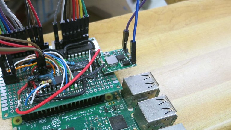


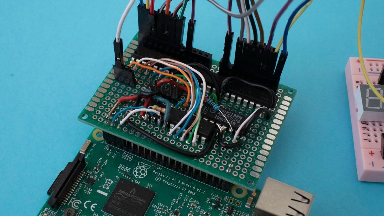
 Since segments A-G were all controlled by a single ULN2003 chip, we started looking closely at every solder joint on that chip. We were looking for an undesirable solder bridge or other electrical connection to any wire relating to segment H, which was managed by another ULN2003 chip.


