
It was a deliberate design choice to build the top and bottom pieces of my LED helix separately, because I wanted to be able to iterate through different end piece designs. The core cylinder hosting most of my LED strip should stay fairly consistent and keeping the same core also meant I wouldn’t have to peel and weaken the adhesive backing for the strip. That said, we need to get this central core set up and running, dangling ends and all, before proceeding further.
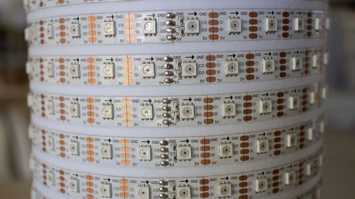
Unwinding the LED strip from its spool onto this cylinder, I found one annoyance: this is not actually a single continuous 5 meter strip, but rather 10 segments, 0.5 meters each, soldered together. The solder joints look pretty good and I have no doubts about their functionality, but this seemed to affect LED spacing. The lengths varied just a tiny bit from segment to segment, enough to make it difficult to keep LEDs precisely aligned vertically.
Once held on to the cylinder with its adhesive backing, I cut the power supply line halfway through the strip by desoldering one of the 5V joints. (Leaving data, ground, and clock connected.) In the near future I will be powering this project with a USB power bank that has two USB output ports, one rated for 1A and other for 2A. Half of the LED strip will run from the 1A port, and the 2A port will run the remaining half plus the Pixelblaze controller.
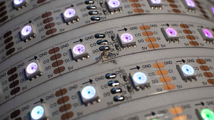
Each end of the LED strip was then plugged into my USB power bank, dangling awkwardly, so I could verify all the LEDs appear to be illuminated and operating from a Pixelblaze test pattern.
Next task: design and print top and bottom end pieces. A bottom end piece to manage the dangling wires and hold that USB power bank inside the cylinder, and a top piece to mount the Pixelblaze.
