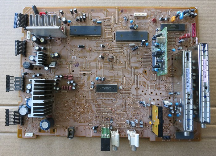
Here are the prizes rewarded for an afternoon spent desoldering parts from a Sony KP-53S35’s signal board “A”.
The most visually striking component were the shiny metal boxes in the corner. This is where signal from the TV antenna enters into the system. RF F-Type connectors on the back panel is connected to these modules via their RCA type connector. Since this TV tuned in to analog TV broadcast signals that have long since been retired, I doubt these parts are good for any functional purpose anymore. But they are still shiny and likely to end up in a nonfunctional sculpture project.


Near these modules on the signal board was this circuit board “P”. It was the only module installed as a plug-in card, which caught our eye. Why would Sony design an easily removable module? There were two candidate explanations: (1) easy replacement because it was expected to fail frequently, or (2) easy replacement because it is something to be swapped out. Since the module worked flawlessly for 21 years, it’s probably the latter. A web search for the two main ICs on board found that the Philips TDA8315T is a NTSC decoder, which confirmed hypothesis #2: this “P” board is designed to be easily swapped for a TV to support other broadcast standards.


The RCA jacks are simple and quite likely to find use in another project.


Miscellaneous ICs and other modules were removed mostly as practice. I may look up their identifiers to see if anything is useful, but some of the parts (like the chips with Sony logo on top) are going to be proprietary and not expected to be worth the effort to figure out what they do.


The largest surface mount chip – which I used as hot air SMD removal practice – was labeled BH3856FS and is an audio processing chip handling volume and tone control. Looking at the flip side of the circuit board, we can see it has a large supporting cast of components clustered near it. It might be fun to see if I can power it up for a simple “Hello World” circuit, but returning it to full operation is dependent on the next item:


What’s far more interesting is nearby: the TDA7262 is a stereo audio amplifier with 20W per channel. This might be powerful enough to drive deflection coils to create Lissajous curves. The possibility was enough to make me spent the time and effort to remove its heat sinks gently and also recover all nearby components that might support it. I think it would be a lot of fun to get this guy back up and running in a CRT Lissajous curve project. Either with or without its former partner, the BH3856FS audio chip above.


