When I began taking apart a refrigerator fan motor, I expected to see simplest and least expensive construction possible. The reality was surprisingly sophisticated, including a hall effect sensor for feedback on fan speed. Seeing it reminded me of another item on my to-do list: I’ve long been curious about how computer cooling fans report their speed through that third wire. The electrical details haven’t been important to build PCs, all I needed to know was to plug it the right way into a motherboard header. But now I want to know more.

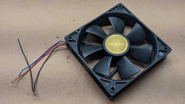
I have a fan I modified for a homemade evaporator cooler project, removing its original motherboard connector so I could power it with a 12V DC power plug. The disassembled connector makes it unlikely to be used in future PC builds and also makes its wires easily accessible for this investigation.

We see an “Antec” sticker on the front, but the actual manufacturer had its own sticker on the back. It is a DF1212025BC-3 motor from the DF1212BC “Top Motor” product line of Dynaeon Industrial Co. Ltd. Nominal operating power draw is 0.38A at 12V DC.

Even though 12V DC was specified, the motor spun up when I connected 5V to the red wire and grounded the black wire. (Drawing only 0.08 A according to my bench power supply.) Probing the blue tachometer wire with a voltmeter didn’t get anything useful. Oscilloscope had nothing interesting to say, either.

To see if it might be an open collector output, I added a 1kΩ pull-up resistor between the blue wire and +5V DC on the red wire.

Aha, there it is. A nice square wave with 50% duty cycle and a period of about 31 milliseconds. If this period corresponds to one revolution of the fan, that works out to 1000/31 ~= 32 revolutions per second or just under 2000 RPM. I had expected only a few hundred RPM, so this is roughly quadruple my expectations. If this signal was generated by a hall sensor, it would be consistent with multiple poles on the permanent magnet rotor.

Increasing the input voltage to 12V sped up the fan as expected, which decreased the period down to about 9ms. (The current consumption went up to 0.22 A, lower than the 0.38 A on the label.) The fan is definitely spinning at some speed far lower than 6667 RPM. I think dividing by four (1666 RPM) is in the right ballpark. I wish I had another way to measure RPM, but regardless of actual speed the key observation today is that the tachometer wire is an open-collector output that generates a 50% duty cycle square wave whose period is a function of the RPM. I don’t know what I will do with this knowledge yet, but at least I now know what happens on that third wire!
[UPDATE: After buying a multichannel oscilloscope, I was able to compare fan tachometer signal versus fan behavior and concluded that a fan tachometer wire signals two cycles for each revolution. Implying this fan was spinning at 3333 RPM which still seems high.]
