
I’ve been pleasantly surprised at how far I was able to revive a Nexus 5X soaked in a public swimming pool for 30 minutes, but I think I’ve reached my limit.
All the phone functions I tested had worked, but using the phone for more than an hour uncovered a serious problem: something related to battery power management is very ill.
The first symptom was heat: the phone got far hotter than it used to, and trying to run the phone while plugged in to the charger resulted in a lot of heat and not a lot of increase in charge level.
I shut the phone down, unplugged it, and set it aside to wait for it to cool. It remained warm for many hours and never cooled. When I turned the phone back on briefly to check, I see the battery charge level has dropped dramatically. Something was draining battery power and turning it into heat even when the phone was turned off.
I knew most phones had two charging programs: One while the phone is on, running under the main operating system. And a second while the phone is off, run by a very minimal piece of code. I’ve already tried the first without success, so I turned off the phone and tried the second. Fortunately this was able to charge the battery though the phone still got pretty toasty.
After the battery was charged again, I disconnected the battery. Only then was the phone able to cool off. When I reconnected the battery, it was quickly obvious the heat source is under one of the pieces of metal shielding, marked in the picture by a red rectangle. I don’t know how to remove that metal shield without destroying the components underneath.
Two hypothesis are open: (1) this circuit was damaged earlier trying to run a ruined battery, or (2) the shield isn’t as watertight as it looks: there’s a lot of pool water chemicals in there corroding parts. Either way, it is beyond my current ability to address, so I have to stop here.
I can’t use this as a phone for more than an hour or two on battery. And I can’t store it with the battery connected because of the drain. So I’m going to disconnect the battery and put it aside in the hope I’ll have better ideas later.


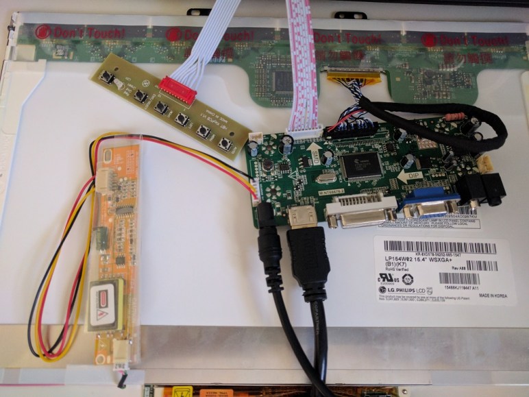
 And it worked! This setup was sufficient to get into the Android OS. Now that the screen is showing more than the “depleted battery” icon, I could see that it was damaged in this adventure. Thankfully it was still legible, and the touchscreen still worked, so I could run the phone for about 40 minutes. Long enough to access the multi-factor authentication app so I could transfer my MFA security to another phone.


 Portable External Monitor version 2.0 (PEM2) explored a different construction technique from PEM1. Instead of building a box by assembling its six side pieces (top, bottom, left, right, front back) the box is built up by stacking sheets of acrylic.

 Once the LCD panel and matching frame had been salvaged from the laptop, it’s time to build an enclosure to hold it and the associated driver board together. Since this was only the first draft, I was not very aggressive about packing the components tightly. It’s merely a simple big box to hold all the bits checking to see if I have all the mounting dimensions for all the circuit boards correct.
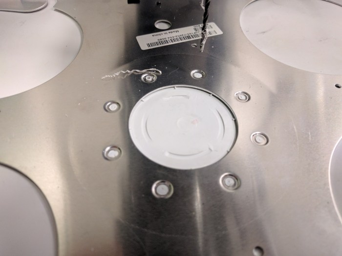 My Luggable PC display was a LCD panel I had salvaged from an old laptop, which I’m doing again for this external monitor project. When I pulled the Luggable PC panel out of the old laptop, I left most of the associated mounting hardware behind. During the Luggable PC project I wished I had also preserved the old mounting hardware.
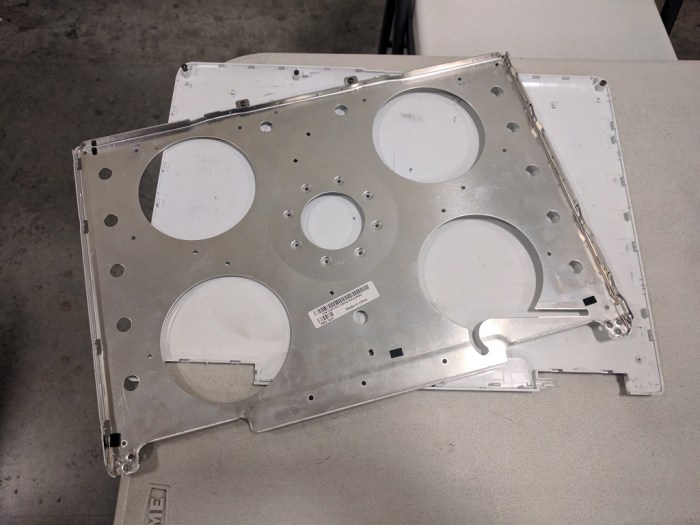


 In the previous post, the laser cutter kerf was successfully compensated, admittedly in a way that left plenty of room for improvement in the future. This post will look at a different challenge of building with acrylic: variation in thickness of acrylic sheets. So far experience showed different sheets of “6 mm” acrylic can actually be anywhere from 5.31 mm to 6.03 mm.
 Since my last fixture project was foiled by laser cutter kerf, I thought I’d try 3D printing the next fixture to avoid laser cutter kerf spoiling my fixture accuracy.
 The end result demonstrated that, even though a 3D printer does not have cutter kerf to compensate for, it introduces other errors in the system. Maybe expensive industrial 3D printers would have enough accuracy to make this fixture work, but my little hobbyist level printer definitely did not. The corners of the box did not mate together as precisely as it did in my mind. The gaps are too wide and uneven for acrylic cement to bridge.
 The current goal is learning how to join pieces of acrylic without introducing tabs that weaken the acrylic pieces. I started simple: a simple corner join between two small pieces, and a fixture to help me do it.
 Before diving into building FreeNAS box #2, I thought I’d take a pause and take a closer look at the acrylic construction results of experiment #1. This is purely about learning to build structures from acrylic – independent from the positive or negative aspects of the project as a computer enclosure.


