See World(s) Online

NASALogoOne of the longest tenure items on my “To-Do” exploration is to get the hang of the Google Earth API and learn how to create a web app around it. This was very exciting web technology when Google seemed to be moving Google Earth from a standalone application to a web-based solution. Unfortunately its web architecture was based around browser plug-ins which eventually lead to its death.

It made sense for Google Earth functionality to be folded into Google Maps, but that seemed to be a slow process of assimilation. It never occurred to me that there are other alternatives out there until I stumbled across a talk about NASA’s World Wind project. (A hands-on activity, too, with a sample project to play with.) The “Web World Wind” component of the project is a WebGL library for geo-spatial applications, which makes me excited about its potential for fun projects.

The Java edition of World Wind has (or at least used to) have functionality beyond our planet Earth. There were ways to have it display data sets from our moon or from Mars. Sadly the web edition has yet to pick up that functionality.

JPL does currently expose a lot of Mars information in a web-browser accessible form on the Mars Trek site. According to the speaker of my talk, it was not built on World Wind. He believes it was built on Cesium, another WebGL library for global data visualization.

I thought there was only Google Earth, and now I know there are at least two other alternatives. Happiness.

The speaker of the talk is currently working in the JPL Ops Lab on the OnSight project, helping planetary scientists collaborate on Mars research using Microsoft’s Hololens for virtual presence on Mars. That sounds like an awesome job.

FreeNAS Box V1 Prototype

FreeNASv1With the concept designed, it’s time to head over to Tux-Lab to build it!

To be honest, it was not fully designed for use as a computer case. Since this was my first effort designing for acrylic construction I expected to run into some amateur mistakes very quickly. As a result I had left some known design issues open to be resolved in future prototypes. One example: I had not designed any kind of door or hinge. The prototype panels are mostly glued together, except for the front panel which is held in place by tape.

Aesthetically, I am pleased with how the clear acrylic looked though I am not pleased at how much of a rat’s nest the power supply cables became. Taming wires is a perpetual challenge. I now understand why Apple enclosed all the ugly guts of the G4 cube in shiny aluminum shell inside the clear acrylic shell.

Other than the messy computer wires, the clear acrylic does hint at the illusion of a computer floating in mid air. I’m pretty happy with that, but it’s not enough to offset the tangle of wires. Next prototype will either have good cable management (takes effort) or have some dark colored acrylic to hide the interior (much easier.)

The cooling functionality worked as designed: the intake air is drawn from the bottom, past the two hard drives keeping them cool, and out the top.

Similarly, the designed goals of tilted-PSU (power supply unit) space optimization was successful, as did the gentler turn demanded of the wires. However, there was an unforeseen deal-breaker of an issue.

Uh-oh!

FreeNASv1_FlawOn the back side of the tilted-PSU, we see that the tilt has pressed the bottom of the PSU up against the wire bundle at the top of the motherboard. The tight quarters mean individual wires of the bundle tried to relieve the crowding by moving into the space for the PSU fan preventing it from turning. Since the PSU fan is the primary air-mover for this enclosure, a stopped fan is obviously not acceptable.

Other notes

Space utilization efficiency has room for improvement. Some of this was caused by the desire to emulate the Apple G4 cube and have a square footprint. (20 cm squared!) The squareness was completely unnecessary and future iteration will likely have a rectangular footprint for space efficiency.

There was uncertainty about how well 3mm acrylic can hold the weight of the power supply unit. It proved to be surprisingly capable once the two top sheets reinforced each other at right angle.

Amateur Hour: A laser cutter only cuts vertically. There was no way to cut a 30 or 60 degree edge for the tilted PSU section! For this learning exercise, the cornered edges are simply left open and unattached.

The angled PSU was a novel idea to solve specific problems, but it caused new ones and also unsuitable for laser cut acrylic construction. That was a fun experiment, but we’ll have to leave the angled PSU concept behind for the next prototype.

FreeNAS Box V1 Design

FreeNASv1_CADOnce the components are gathered, we start thinking about designing an enclosure for them. The tool of choice is the Tux-Lab laser cutter. The material of choice is acrylic sheet. The objective of the exercise is to learn how to build with acrylic and ideally create something novel and unique.

Since my mind is already on acrylic, it was a short jump to think about the Apple Power Mac G4 Cube. A landmark of industrial design. Obviously what I make won’t be as pretty, but it’ll be my homage to the cube. Here are the two main design considerations in my FreeNAS experiment #1.

Hard Drive Cooling

Heightwise
Airflow along the sides has small surface area.
Lengthwise
Airflow lengthwise has large surface area, but will be obstructed by data and power cables.


Crosswise
Airflow crosswise has large surface area and will not be obstructed by data and power cables.

Since the goal is for low power, low noise, and small size, I didn’t want to add any fans. The small fan on the processor and the large fan in the power supply will take care of their respective components. That leaves the two hard drives without their own cooling, so the enclosure will have to utilize airflow created by the power supply fan.

We desire the maximum cooling surface area that presents the fewest obstructions to the air stream. And we want to work with (instead of against) natural convection forces. Evaluating the possibilities, the best choice is to align cross-wise airflow to be vertical by sitting the hard drives on their long sides.

Power Supply Spacing

PSU Upright
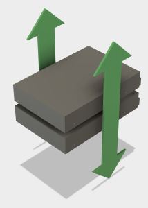
Following the lead of the G4 Cube, air intake will be on the bottom and the power supply (with its fan) will sit at the top to work alongside natural convection and exhaust hot air.PSU Tilted

With the power supply sitting at the top, and the hard drives sitting on their sides against the bottom, that leaves a fairly large piece of unused space. The wires protruding from the power supply is also a concern. We either have to force those wires to make sharp downward turns to reach the system components, or we have to increase the depth of the enclosure to give the wires room.

Our experiment #1 tilts the power supply downward 30 degrees to utilize the available space to relieve the wire spacing issue.

Will these ideas work? Let’s build it and find out…


Components for FreeNAS Project

I wanted to play with FreeNAS without spending a lot of money to build the computer to run it. In fact, I would prefer not spending any money at all. This is a lot like how the Luggable PC project started: figuring out the most interesting thing I can do with computer parts I already had on hand.

AM1I
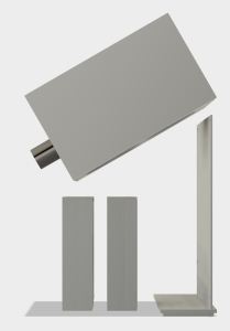
The brains of the system will be a Mini-ITX board, the MSI AM1I. I got this board a few years ago, along with its AMD Athlon 5350 processor while they were on sale at Fry’s Electronics together as a bundle. This pair has participated in many experiments and projects since. It was visible in some early Luggable PC project pictures, mostly of the January 2016 “Easel Frame” phase. And now, it will play host to the FreeNAS project.

The storage will be provided by two Seagate 2TB hard drives. These drives were part of my Windows Home Server and had been gathering dust ever since the server was decommissioned. They will now re-enlist to serve as storage for the home network.

The power will be provided by an ATX power supply that I’ve relegated to standby/ backup status. In its old age it has started to develop some coil whine. While it has not yet become a functional issue, the noise is unpleasant coming from a computer on my desk. Which makes it the ideal candidate for powering a NAS box stored someplace out of the way, probably out of sight, and best of all, out of hearing range.

I could throw all these pieces into a commercially available case, and call the physical setup done and turning this FreeNAS project into a strictly software learning exercise. But where’s the fun in that?

When I said I wanted to build a FreeNAS box I meant that literally: I want to build the physical box to enclose the above components.

My FreeNAS Project Begins

FreeNAS LogoRecently I lost access to my Amazon Drive for approximately 72 hours. There was no data loss, merely interrupted access, but it highlighted the fact that cloud-based storage can disappear on me just like any other kind of storage. This experience moved a back-burner project up to the front burner: adding NAS (Network Attached Storage) to my home network to supplement the (relatively) small SSDs in my computers.

I used to have a Windows Home Server on my home network, which presented network storage as part of its feature set. Sadly for me Microsoft had abandoned that product line, so I decommissioned my machine with no network-based replacement. I moved back to straightforward USB hard drives at home to supplement my cloud-based storage.

Since I’m not entirely sure a 24×7 network-accessible storage would be useful enough for me to justify the electric bill, I didn’t want to go out and spend several hundreds of dollars on a Drobo or similar commercially-available NAS. I also wanted to learn more about this part of the computing world. Drobo (& friends) are designed to be super easy to use, set-and-forget computing appliances. I wanted to see a little bit more under the hood and get a better feel of the nuts-and-bolts.

A desire for lower up-front cost and an interest in seeing the guts… sounds like time for an open source software solution! And like most open source solutions, there are several different projects, some with multiple forks, all proclaiming to be the best solution to the problem.

I decided to try FreeNAS as a starting point. The code base has been around a while (though supposedly extensively rewritten recently) and it is currently funded by iXsystems who makes money by selling storage solution for businesses. (Basically hardware specifically built to run FreeNAS.) So the product has some history, and has a funding source to help make sure it has a future. Both are good things.

Sounds promising, so let’s build a FreeNAS Box!

Luggable Frame Experiment #2

Catleap2The second iteration of the luggable frame experiment addressed the failings of the first version by relying less on acrylic and more on aluminum. The first iteration was a good experiment to see if acrylic was strong enough for the work. Once V1 conclusively proved the weaknesses, it’s time to fall back to the known quantity.

The following changes were made for version 2:

Extrusion upgrade: In the interest of greater rigidity, the extrusions themselves were upgraded from Misumi HFS3 (15mm x 15mm cross section) to HFS5 (20mm x 20mm). The smaller extrusions seemed to be doing the job but they did exhibit some flex. And we had HFS5 conveniently on hand so let’s use it!

Connection upgrade: In V1 the extrusion T-joint at the base of the frame was held together by the side pieces of acrylic. Though it seemed to work, V2 went with a stronger solution by using metal connectors for the joint. (Misumi HBLFSNF5).

Handle upgrade: The V1 handles were part of the acrylic assembly. With the reduction in acrylic usage, there wasn’t enough left to carry the load of the whole frame. So the handle became another aluminum extrusion.

Catleap2-RearPC tray upgrade: This was the first acrylic thing that failed in V1. The PC is now held in place by aluminum structure instead of an acrylic cutout which makes it quite secure. Three of the extrusion right-angle connectors were re-purposed as “claws” to keep the PC case in place.

Catleap2-SideVESA mount upgrade: The worrisome flex in the Catleap monitor enclosure was traced down to the metal threads inside the Catleap enclosure that were longer than the thickness of the enclosure plastic. This meant when the mounting screws fully engaged, there was still a bit of space between the VESA mount plate and the monitor’s rear surface, allowing movement. A spacer plate was added to fill that gap. Now the VESA mounting plate on the frame is fully pressed against the monitor’s rear surface, greatly reducing the flex.

All this additional structure added up to a very secure frame for carrying around the Yamakasi Catleap monitor with the HP Z220 computer. Unfortunately it also added weight which was a concern even before the frame came into the picture. The heft means this is probably the end of the line for the Catleap + Z220 experiments. Frame V2 will serve as a perfectly good workstation albeit not a very portable one.

The idea of building a Luggable PC around a commercially available monitor will continue, with the focus shifting to using smaller and lighter components.

Fusion 360 Foundational Concepts Tutorial

foundational-concepts-iconI went back into Autodesk’s Fusion 360 learning resources for a refresher and to set myself up to learn the Fusion 360 CAM modules. The last time I went through the tutorials, I had skipped the CAM functionality because I had no machine tools and were not likely to get time on anybody else’s machinery. Now that I might be able to access Tux-Lab fabrication machinery, I wanted to make sure I won’t break the machine from doing anything stupid in Fusion 360.

Before I got to CAM, though, the “Foundational Concepts” section caught my attention. I either didn’t see it the last time or it made no impression on me at the time. I went through the set of short videos and they were surprisingly informative. Most tutorials for Fusion 360 (and most other software packages in general) are happy to tell users how to accomplish their tasks. This is a slightly different twist – the foundation concepts talk about why Fusion 360 is the way it is. About how they tried to restructure a CAD package for the cloud-based future, about how they restructured the workflow to take advantage of today’s level of computation power at our fingertips, so on and so forth.

I come from a software engineering background and I’m all too aware of the fact that the end user typically has no idea what the software developer had intended as they built the piece of software. It can be argued that the end user doesn’t need to know anything about the intent if the software is sufficiently well-designed. But for something complex like a CAD package, I believe there is value in learning the motivation behind the design.

And even if the user doesn’t need to know, sometimes the user is curious and wants to know. I appreciate the Fusion 360 user education team for putting this information out there available for those who want to know.