My normal home dental routine includes daily Waterpik cleaning, which has been great for my teeth but there’s a cost. Water and electrical mechanics do not peacefully coexist (just ask anyone who owns a boat) which might be why my Waterpik machines haven’t lasted very long. A few years ago I took apart a battery-powered Waterpik that had died, today I am taking apart another.

This one is powered by household AC and it hasn’t quite died. However, it is noticeably less powerful than it used to be. When it was too weak to dislodge a piece of food wedged between my teeth at maximum strength setting, I replaced it with a new unit to restore full teeth-cleaning power. I want to see if I can find any sign of wear and tear that would explain the reduced strength.

An electrical appliance that has water running through it is definitely presents a risk for electrical shock! I’m going to disregard the warning on this bottom label and open it anyway, as I don’t intend to put it back together or run water through it again.

Adjacent to the label is a socket for the handheld wand. Removing the plug unveiled a rubber O-ring seal, which was expected, and this tan-colored flap of plastic, which was unexpected. I see a mesh texture that made me think it might be some sort of filter, but it is not a mesh and seems fully watertight. My best guess is some sort of backflow prevention.

I didn’t expect to find much inside the handheld wand, but I cut it open anyway to confirm. The on/off water flow valve seems fine and there’s no sign of obstruction.

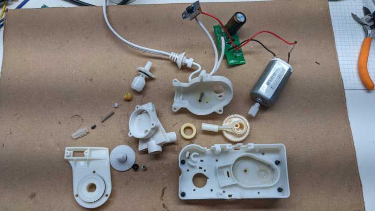
Returning to the base, I removed four Philips-head fasteners between base and enclosure. The strength adjustment knob also had to be pulled out before the enclosure can move.

Inside the enclosure we see a black cylinder where water is fed from a reservoir, and we can see a bit of orange colored sealant to make the joint watertight. The gear-looking thing is for the power switch. It looked and felt like a rocker switch, but it actually has this rack-and-pinion mechanism to translate the rocking motion to a linear sliding switch. If the designers wanted a rocker switch, why didn’t they use an actual rocker switch for household AC? This mechanism feels like unnecessary complexity.
We also see signs of a fine black dust/powder inside, more details on that shortly.

After the sliding switch, AC power is fed through an array of diodes for rectification. A big capacitor smooths output and a resistor drains residual charge from the capacitor after use. [UPDATE: A comment pointed out my mistake, the resistor is not in parallel with the capacitor. It is in series with line input, which is consistent with a resistor for controlling inrush current.] The strength knob has no involvement in the electrical side at all, the motor always runs at full speed and jet strength is a strictly mechanical affair.

I had expected the power to go straight into an AC motor, but that rectifier circuit was necessary as this is actually a 120V DC motor. Something about this DC motor was worth adding the cost of rectification circuit board, I’m curious what tradeoffs are involved.

A disadvantage of DC motors is the need for commutator and brushes, which wears over time. That black dust deposited all around enclosure interior are little bits of vaporized motor brush and commutator flowing out of the motor like smoke, as we can see here. Worn commutator/brushes is the first visible candidate explanation for reduced strength of this device.

Here is the jet strength adjustment mechanism. The spring-loaded gasket at the bottom pushes against the adjustment disc, which has a thin groove through it. It looks like turning the dial adjusts how much of the thin groove is presented to water flow, sapping its strength on longer journeys.

But that is only a guess, because I’m not confident I understand how this system works. Here is the water reservoir intake assembly, which presents two paths for water coming in from the reservoir. One through the holes at the side of a narrow neck, and the other through a spring-loaded contraption for purposes I don’t understand. Once this assembly was removed, I could see the intake tube actually goes all the way through to the exit for the handheld wand.

For the Waterpik to function, all of this must implement a system to ensure one-way flow of water, but I have trouble visualizing how the hydrodynamic forces would interact to make that happen. Disassembling the spring-loaded contraption got me no closer to illumination. Somewhere in here might be the answer to reduced strength as this device aged, but I couldn’t begin to guess how.

The water-pumping piston assembly was relatively straightforward. Motor shaft output is geared down to a crank to move the piston back and forth through its cylinder. No signs of water intrusion and all the lubricants still in place explains why there are no signs of wear or play in the mechanism. Whatever caused this Waterpik to weaken over time, it’s probably not here.

The best hypothesis so far is wear and tear on DC motor brush and commutator. I want to open it up for a look, but the motor is held by these metal tabs bent from the motor can. Roughly one millimeter of steel is too stout for me to bend out of the way with pliers.

Which means it’s time for the Dremel cutting disc!

Once those two tabs were cut out of the way, I could remove the white plastic end cap and see the motor commutator and brushes. They are very definitely worn, but I wouldn’t have expected this level of wear to cause a severe degradation in output power.

This Waterpik base managed to keep a few a secrets even when disassembled. I still don’t understand the complexity of how water flow is restricted to be one-way, and I failed to find an obvious explanation for a weak output jet. At the rate I’m wearing them out, though, I’m sure I’ll have another opportunity in a few years.

On the Waterpik WP-150 teardown, is the resistor connected so as to discharge the capacitor or us is it connected in series with the line cord? The circuit board appears to be the same as that in our WP-310 whose resistor is in series with one leg of the line cord, leading to the D1/D3 junction – in this circuit location it doesn’t discharge the capacitor but does serve to limit the inrush currents to the capacitor and motor to about 3.6A total when the unit is initially turned on, protecting the diodes and motor from excessive peak current. The capacitor serves as a low pass filter to smooth voltage ripple and reduces brush sparking and wear. There’s no need for a discharge resistor in parallel with the capacitor as the motor serves this function.
It would be helpful to list the resistor’s value, from the video the first three bands appear to be yellow/purple/black corresponding to 47ohms, with the gold band indicating 5% tolerance – one also could measure its value. Its physical size suggests 1 Watt. This resistor commonly burns out when 120VAC units are plugged into 220VAC – the overheating destroys the bands’ color and there’s much discussion on the internet about the proper value for a replacement resistor. Diodes, the thermal fuse, and motor also might be damaged (all available and inexpensive), but often replacing the resistor is sufficient.
LikeLike
I thought I determined the resistor was wired in parallel with the capacitor but, after reading your comment, I went back and reviewed the circuit and found I was wrong. It is indeed in series with line in and diodes, consistent with inrush current control. Thanks for the correction!
LikeLike
Thanks for the confirmation. I’ve been pondering what might be causing your drop in output. Have you checked the value of the resistor? If it is aging upward that could be responsible, if so you could try a 2 watt unit of the same value. The motor brushes had plenty of material and the commutator probably was okay though it could be cleaned up with fine emory cloth. New motors are inexpensive, as low as 8 US$.
LikeLike
im just tearing mine apart. my Issue is identical to yours. What I found was that the “tan-colored flap of plastic, ” that you described was missing in mine. I believe it had actually just disintegrated over time. You could see a “shadow” imprint of where it sat. The disc is responsible for preventing the back flow and allows pressure to build up. My guess is your disc was cracked….mine was missing and thus the pressure was weak and un adjustable. I read on a forum that a replacement can be made from the plastic on a soda bottle. Ill give it a shot but its a very small “wafer thin” part.
great tear down. good info!
LikeLike