Extracted Magnets from Broken iPad Case

This was an aftermarket protective cover case designed to fit 6th generation Apple iPad tablets. Purchased from the lowest bidder on Amazon that day (*) it did its job for several years absorbing abuse until a corner broke off and the case could no longer latch in place. It turned out a case that wouldn’t stay attached was worse than no case at all, as the iPad fell out causing a dent on the back.

While remaining three corners of this case were still attached, they all showed cracks in the plastic. Thus it was retired and replaced with a new case. Before this broken case is sent to landfill, though, I wanted to salvage its embedded magnets. This cover has the option to fold into a stand, held in shape by magnets. Closing the cover is also something detectable by the iPad, so there’s a Hall sensor inside the tablet picking up a precisely located magnet.

Using a screwdriver for its steel shaft, I could feel tugs at several locations indicating a magnet. Given how thin they must be, I expected to find a few tiny slivers of rare-earth magnets. And given the thin fabric construction, I decided to start by cutting an edge with scissors.

First magnet was quickly uncovered.

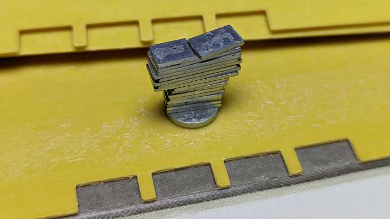
Pulling on the glued-on fabric, I uncovered the remaining magnets embedded within the first panel. Four small rectangular magnets near the middle of the edge. Surrounded by two larger rectangular magnets on either side. There’s a circular magnet as well, away from the rest. I had only expected one or two magnets, so this is an unexpected bounty.

The magnets weren’t attached to the yellow plastic backing at all, merely held in place by adhesive on either side. They could be peeled off with minimal residue. This is working out really well.

Continued peeling discovered another circular magnet in the middle panel, and another set of rectangular magnets on the third panel that matched the arrangement of magnets in the first panel. Those two arrays of rectangular magnets on outermost edges would implement the fold-into-a-stand function. The two circular magnets don’t line up to each other, I guess they are there for iPad “cover is closed” detection.

I cut into this cover expecting just a magnet or two, so I’m very happy I came out with a stack of 18 little magnets. They are very thin so it should be easy to fit them into places in future projects. In fact, they are so thin I need to worry about protecting them. This material is brittle: I broke that topmost magnet in half when peeling it off the adhesive layer, a lesson warning me to be careful with the rest.


(*) Disclosure: As an Amazon Associate I earn from qualifying purchases.

AS7341 Spectral Color Sensor with Mozzi on AVR Arduino

Looks like I will never learn how to build custom configurations for AS7341 SMUX, but at least I have presets I could copy/paste and that’s good enough for my hobbyist level project. The goal is to convert I2C communication from Arduino’s standard Wire library to the twi_nonblock library bundled as part of Mozzi library. Arduino Wire library would block execution while I2C communication is ongoing, which causes audible glitches with Mozzi sketches. Converting to twi_nonblock avoids that issue.

Using Adafruit’s AS7341 Arduino library and sample sketches as my guide, it was relatively straightforward to converting initialization routines. Partly because most of them were single-register writes, but mostly because non-blocking isn’t a big concern for setup. I could get away with some blocking operations which also verified I2C hardware was working before adding the variable of nonblocking behavior into the mix.

To replicate Adafruit’s readAllChannels() behavior in a nonblocking manner, I split the task into three levels of state machines to track asynchronous actions:

  • Lowest level state machine tracks a single I2C read operation. Write the address, start a read, and copy the results.
  • Mid level state machine pulls data from all 6 AS7341 ADC. This means setting up SMUX to one of two presets then waiting for that to complete. Start sensor integration, then wait for that to complete. And finally copy sensor results. Each read operation is delegated to the lower level state machine.
  • High level state machine runs the mid-level state machine twice, once for each SMUX preset configuration.

Once that high level state machine runs through both SMUX preset configurations, we have data from 10 spectral sensors. The flicker detector is the 11th sensor and not used here. This replicates the results of Adafruit’s readAllChannels() without its blocking behavior. Getting there required an implementation which is significantly different. (I don’t think I copied any Adafruit code.)

While putting this project together, my test just printed all ten sensor values out to serial console. In order to make things a little more interesting, I brought this back full circle and emulated the behavior of Emily Velasco’s color organ experiment. Or at least, an earlier version of it that played a single note depending on which sensor had returned highest count. (Emily has since experimented with vibrato and chords.) I added a lot of comments my version of the experiment hopefully making it suitable as a learning example. As a “Thank You” to Emily for introducing me to the AS7341, I packaged this project into a pull request on her color organ repository, which she accepted and merged.

This is not the end of the story. twi_nonblock supports only AVR-based Arduino boards like the ATmega328P-based Arduino Nano I used for this project. What about processors at the heart of other Arduino-compatible boards like the ESP32? They can’t use twi_nonblock and would have to do something else for glitch-free Mozzi audio. That’ll be a separate challenge to tackle.


Code for this project is publicly available on GitHub.

Sample Code Gave Incomplete Picture of AS7341 SMUX Configuration

Reading through Adafruit AS7341 Arduino library implementation of readAllChannels(), I was happy to see it mostly confirmed information I understood from datasheet reading. It also had something else: how to configure AS7341 sensor multiplexor (SMUX). Details of which were critical information completely missing from the datasheet, mere a note that AMS provides sample code. [Update: Details were in an Application Note.] I say sample code is a poor substitute for proper documentation and my position remains unchanged.

I thought I might have a good shot at figuring out SMUX configuration registers, given that I have found three sample points. DFRobot has an Arduino AS7341 library. Adafruit has their own implementation of an Arduino AS7341 library. And hidden in the examples folder of Adafruit’s library is an Arduino sketch that doesn’t use Adafruit’s library at all, written by an AMS application support engineer. Comparing and contrasting between them should tell me a lot!

Unfortunately, as soon as I took a closer look my expectation went down in flames. These three examples are writing the exact same bytes to the exact same registers. There’s nothing to compare and contrast at all. This feels like someone at AMS wrote a SMUX configuration at one point and it’s just been copied and pasted ever since. All we really have to work with are the skimpy comments in these configuration routines.

Based on these comments, each register corresponds to a single sensor, except when it controls two sensors. Bits in the register control which ADC is connected. It was easy to infer that zero representing no connection to any ADC at all, but other than that the bits are inconsistent. Setting register 0x0F to 0x30 supposedly connected to ADC2, but for register 0x0A it was 0x03 that connected to ADC2. Some of the sensors have a “left” and “right” but it’s not clear what that means. My best guess is from the datasheet figure showing sensor array layout:

Maybe “F3 left set to ADC2” means connecting only the left side F3 sensor, leaving the right side F3 sensor unused? That would mean we’re using half the available sensor area to gather light, which seems sub-optimal.

And most critically, the comments weren’t enough for me to figure out how I’d create a different SMUX configuration. There’s nothing about any of these in the datasheet, which remains my biggest complaint to AMS. The only description I found in the datasheet is that flicker detection sensor must be connected to ADC5.

One odd thing I noticed about this copied-and-pasted code snippet is the fact it sends twenty bytes of SMUX configuration as twenty write operations of single bytes to sequential registers 0x00 through 0x13 inclusive. Why do it in such an efficient way? For my project I converted that to a faster and more efficient single write operation of twenty bytes and it seems to work.

The good news is that these sample code snippets help us configure SMUX to do something useful in line with functionality demonstrated by these samples. The bad news is that we don’t have enough information to design and build our own SMUX configurations to suit specific needs. I guess if someone wants to use AS7341 professionally they can ask AMS application support team to build a custom SMUX configuration for them. For an electronics hobbyist like myself, these fixed configurations are sufficient for me to complete my project, but I am still grumpy with AMS about it.


Code for this project is publicly available on GitHub.

Unrolling Adafruit AS7341 readAllChannels()

After successfully reading an AS7341’s product ID via a non-blocking I2C API, I have gained confidence I can replicate any existing AS7341 library’s actions with the non-blocking I2C API. This way it will play nice with Mozzi library. I decided to focus on Adafruit_AS7341::readAllChanels() because it seemed like the most useful one to convert to non-blocking operation. It was used in multiple examples as well as Emily’s color organ project.

bool Adafruit_AS7341::readAllChannels(uint16_t *readings_buffer) {

  setSMUXLowChannels(true);        // Configure SMUX to read low channels
  enableSpectralMeasurement(true); // Start integration
  delayForData(0);                 // I'll wait for you for all time

  Adafruit_BusIO_Register channel_data_reg =
      Adafruit_BusIO_Register(i2c_dev, AS7341_CH0_DATA_L, 2);

  bool low_success = channel_data_reg.read((uint8_t *)readings_buffer, 12);

  setSMUXLowChannels(false);       // Configure SMUX to read high channels
  enableSpectralMeasurement(true); // Start integration
  delayForData(0);                 // I'll wait for you for all time

  return low_success &&
         channel_data_reg.read((uint8_t *)&readings_buffer[6], 12);
}

Examining this code, we can see it does the same thing twice, differing only in a single boolean parameter to setSMUXLowChannels. This reflects AS7341 architecture where we have more sensors than ADCs so we have to configure SMUX to read a subset then reconfigure SMUX to read remaining sensors.

void Adafruit_AS7341::setSMUXLowChannels(bool f1_f4) {
  enableSpectralMeasurement(false);
  setSMUXCommand(AS7341_SMUX_CMD_WRITE);
  if (f1_f4) {
    setup_F1F4_Clear_NIR();
  } else {
    setup_F5F8_Clear_NIR();
  }
  enableSMUX();
}

Digging into setSMUXLowChannels we see the following actions:

  1. enableSpectralMeasurement disables a register bit to turn off spectral measurement, necessary preparation for SMUX reconfiguration.
  2. setSMUXCommand flips a different register bit to notify AS7341 that a new SMUX configuration is about to be uploaded.
  3. Upload one of two SMUX configurations, depending on boolean parameter.
  4. enableSMUX repeatedly reads a register bit until it flips to 0, which is how AS7341 signifies that SMUX reconfiguration is complete.

Steps 1-3 above are I2C writes and can be done quickly. Step 4 will add complication: not only is it an I2C read, but we might also need to read it several times before the bit flips to zero.

Backing out to readAllChannels, we see spectral measurement bit is flipped back on after SMUX reconfiguration. According to the datasheet, flipping this bit back on is a signal to start a new reading. How do we know when sensor integration is complete? That’s indicated by yet another register bit. delayForData repeatedly reads that until it flips to 1, clearing the way for us to read 12 bytes of sensor data. Representing data from all six ADCs channels, each of which gives us 16 bits (2 bytes) of data.

Unrolling all of the above code in terms of I2C operations, readAllChannels breaks down to:

  1. I2C register write to turn OFF spectral measurement.
  2. I2C register write to notify incoming SMUX configuration data.
  3. I2C write to upload SMUX configuration for ADC to read sensors F1 through F4, plus Clear and NIR channels.
  4. Repeated I2C read for “SMUX reconfiguration” flag until that bit flips to 0.
  5. I2C register write to turn ON spectral measurement. (Starts new sensor integration.)
  6. Repeated I2C read for “Sensor integration complete” flag until that bit flips to 1.
  7. I2C read to download sensor data
  8. Repeat 1-7, except step #3 uploads SMUX configuration for sensors F5 through F8 instead of F1 through F4.

I like this plan but before I roll up my sleeves, I wanted to take a closer look at SMUX configuration.


Code for this project is publicly available on GitHub.

Hello AS7341 ID via Non-Blocking I2C

I’ve refreshed my memory of Mozzi and its twi_nonblock API for non-blocking I2C operations, the next step is to write a relatively simple Hello World to verify I can communicate with an AS7341 with that API. While reading AS7341 datasheet I noted a great candidate for this operation: product ID and revision ID registers.

In order to use twi_nonblock we need to break a blocking read() up to at least three non-blocking steps in order to avoid glitching Mozzi sound:

  1. We start with an I2C write to tell the chip which register we want to start from. Once we set parameters, I2C hardware peripheral can do the rest. In the meantime, we return control to the rest of the sketch so Mozzi can do things like updateAudio(). During each execution of updateControl() we check I2C hardware status to see if the write had completed. If it’s still running, we resume doing other work in our sketch and will check again later.
  2. If step 1 is complete and address had been sent, we configure I2C hardware peripheral to receive data from A7341. Once that has been kicked off, we return control to the rest of the sketch for updateAudio() and such. During each execution of updateControl() we check I2C hardware status to see if data transfer had completed. If it’s not done yet, we resume running other code and will check again later.
  3. If data transfer from AS7341 is complete, we copy the transferred data into our sketch and our application logic can take it from there.

My MMA_7660 sketch tracked above states #1-3 within updateControl(), following precedence set by Mozzi’s ADXL354 example. But that was a simple sensor to use, we just had to read three registers in a single operation. AS7341 is a lot more complex with multiple different read operations, so I pulled that state machine out of updateControl() and into its own method async_read(). The caller can keep calling async_read() on every updateControl() until the state reaches ASYNC_COMPLETE, at which point the process stops waiting for data to be copied and processed. Whenever the caller is ready to make another asynchronous read, they can set the state to ASYNC_IDLE and the next async_read() will start the process again.

As a test of this revamped system, I used it to read two bytes from AS7341 starting at register 0x91. 0x91 is for revision ID and the following byte 0x92 is the product ID. I wasn’t sure what to expect for revision ID, I got zero. But according to the datasheet product ID is supposed to be 0x09, and that matches what I retrieved. A great start! Now I can dig deeper and figure out how to read its sensors with nonblocking I2C.


Code for this project is publicly available on GitHub.

Refresher on Mozzi Timing Before Tackling AS7341

I’ve decided to tackle the challenge of writing a Mozzi-friendly way to use an AS7341 sensor, using nonblocking I2C library twi_nonblock. At a high level, this is a follow-up to my MMA7660 accelerometer Mozzi project several years ago. Due to lack of practice in the meantime I have forgotten much about Mozzi and need a quick refresher. Fortunately, Anatomy of a Mozzi sketch brought most of those memories back.

I connected a salvaged audio jack to the breadboard where I already had an Arduino Nano and my Adafruit AS7341 breakout board. (The AS7341 will sit idle while I refamiliarize myself with Mozzi before I try to integrate them.) After I confirmed the simple sine wave sketch generated an audible tone on my test earbuds, I started my first experiment.

I wanted to verify that I understood my timing constraints. I added three counters: the first is incremented whenever loop() is called. The second when Mozzi calls the updateControl() callback, and the third for updateAudio() callback. Inside loop(), I check millis() to see if at least one second has passed. If it had, I print values of all three counters before resetting them back to zero. This test dumps out the number of times each of these callbacks occur every second.

loop 165027 updateControl 64 updateAudio 16401
loop 164860 updateControl 63 updateAudio 16384
loop 165027 updateControl 64 updateAudio 16401
loop 164859 updateControl 64 updateAudio 16384
loop 165027 updateControl 64 updateAudio 16401
loop 164860 updateControl 63 updateAudio 16384
loop 165028 updateControl 64 updateAudio 16400
loop 164859 updateControl 64 updateAudio 16385
loop 165027 updateControl 64 updateAudio 16400
loop 164858 updateControl 64 updateAudio 16384
loop 165029 updateControl 63 updateAudio 16401
loop 164858 updateControl 64 updateAudio 16384
loop 165027 updateControl 64 updateAudio 16401
loop 164858 updateControl 64 updateAudio 16384
loop 165029 updateControl 64 updateAudio 16400
loop 164860 updateControl 63 updateAudio 16384

Arduino framework calls back into loop() as fast as it possibly can. In the case of this Mozzi Hello World, it is called roughly 165,000 times a second. This represents a maximum on loop() frequency: as a sketch grows in complexity, this number can only drop lower.

In a Mozzi sketch, loop() calls into Mozzi’s audioHook(), which will call the remaining two methods. From this experiment I see updateControl() is called 63 or 64 times a second, which lines up with the default value of Mozzi’s CONTROL_RATE parameter. If a sketch needs to react more quickly to input, a Mozzi sketch can #define CONTROL_RATE to a higher number. Mozzi documentation says it is optimal to use powers of two, so if the default 64 is too slow we can up it to 128, 256, 512, etc.

We can’t dial it up too high, though, before we risk interfering with updateAudio(). We need to ensure updateAudio() is called whenever the state of audio output needs to be recalculated. Mozzi’s default STANDARD mode runs at 16384Hz, which lines up with the number seen in this counter output. If we spend too much time in updateControl(), or call it too often with a high CONTROL_RATE, we’d miss regular update of updateAudio() and those misses will cause audible glitches. While 16 times every millisecond is a very high rate of speed by human brain standards, a microcontroller can still do quite a lot of work in between calls as long as we plan our code correctly.

Part of a proper plan is to make sure we don’t block execution waiting on something that takes too long. Unfortunately, Arduino’s Wire library for I2C blocks code execution waiting for read operations to complete. This wait is typically on the order of single-digit number of milliseconds, which is fast enough for most purposes. But even a single millisecond of delay in updateControl() means missing more than 16 calls to updateAudio(). This is why we need to break up operations into a series of nonblocking calls: we need to get back to updateAudio() between those steps during execution. Fortunately, during setup we can get away with blocking calls.

New Project: Mozzi + AS7341

After looking at Adafruit’s AS7341 library and its collection of example sketches, I will now embark on a new project: make Mozzi play nice with AMS AS7341 sensor. If successful, it would solve a problem for my friend Emily Velasco who got me interested in the AS7341 to begin with. Her project uses Mozzi library to generate sounds but calls into AS7341 API would cause audible pops.

The problem is that AS7341 libraries from Adafruit and DFRobot both use Arduino’s Wire library for I2C communication. (Adafruit actually goes to their BusIO library which then calls into Wire.) These are blocking calls meaning the microcontroller can’t do anything else until the operation completes. This is especially problematic for I2C reads: We have to perform a write to send the register address we want to read from, then start a read operation, and wait for the data to come in. This operation is usually faster than an eyeblink, but that’s still long enough to cause a pop in Mozzi audio.

To help solve this problem, Mozzi includes a library called twi_nonblock. It allows us to perform I2C operations in a non-blocking manner so Mozzi audio can continue without interruption. Unfortunately, it is a lot more complicated to write code in this way, and it only supports AVR-based Arduino boards, so people usually don’t bother with it. Mozzi includes an example sketch, altering sounds based on orientation of an ADXL345 accelerometer. A few years ago, I took that example and converted it to run with a MMA7660 accelerometer instead.

If I could interface with an AS7341 using Mozzi’s twi_nonblock, it would allow color-reactive Mozzi sketches like Emily’s to run on AVR-based Arduino boards without audio glitches. But the AS7341 is far more complex than a MMA7660 accelerometer. I’ve got my work cut out for me but if it works, I will gain a great deal of confidence and experience on the AS7341 as well as a refresher on working with Mozzi.


Code for this project is publicly available on GitHub.

Notes on Adafruit AS7341 Arduino Library Example Code

I’ve purchased an AS7341 breakout board from Adafruit (#4698) and read through their guide (single-page view) on the board. It’s nice to see their library takes care of the complexity of this chip’s internals such as SMUX configuration. Examples that come bundled with a library is always a good overview of capabilities, and this is what I see from its examples directory:

  • basic_counts: “Basic Counts” is a concept described in the AS7341 calibration application note. A bit of math that takes raw sensor counts and compensates for gain and integration time. AMS recommends application logic work with “Basic Counts”. This lets us change gain and integration based on environment and still keep the rest of the application logic unchanged.
  • flicker_detection: Prime concern of flicker detection is with household AC power frequencies of 50Hz or 60Hz however this sensor is not limited to those rates. The datasheet says it can detect flicker frequencies up to 2kHz. This capability feels like a potential project all by itself, I’ll have to think more about it.
  • get_channel: Performs a read of all channels then iterates through 10 spectral sensing channels of 8 visible spectrum + clear + infrared to print their raw counts. (Flicker detection channel is ignored.)
  • gpio_example: Using the “GPIO” pin as a digital output. High for 3 seconds and low for half a second and repeat. Important note: according to board schematic published by Adafruit, the GPIO pin is brought out directly to the headers. There is no voltage level shifting or protection on this pin so be sure to consult datasheet and be nice to this 1.8V part.
  • gpio_input_example: Using the “GPIO” pin as digital input. Samples every half second and prints either “high” or “low” to serial console.
  • led_test: The canonical “blink a LED” test implemented with the LED Adafruit installed on the breakout board connected to AS7341’s LDR pin. Lights up at 4mA for 1/10th of a second, dark for half a second, light up to 100mA for 1/10th of a second, dark for another half a second, and repeat. Note while the AS7341 constant current control register goes up to 258mA, we shouldn’t go that far. According to board schematic published by Adafruit, the onboard LED is an EAHC2835WD6 with recommended ceiling of 150mA and absolute maximum of 180mA.
  • plotter_example: A clever variation on get_channel designed to work with Arduino IDE’s Serial Plotter feature. Five comma-separated sensor values are printed on a line so that when we turn on Serial Plotter, the plotter line drawing colors are close to the color wavelength of that sensor.
  • read_all_channels: This is almost identical to get_channel. The only difference is this sketch passes an array into the call to readAllChannels() and prints from sketch’s own array. get_channel does the exact same thing using the array stored in Adafruit library object.
  • reading_while_looping: Most of these examples call readAllChannels(), which is a blocking call that waits for sensor integration to complete before returning with results. Depending on integration time configuration, delay caused by waiting can be problematic. This sketch illustrates a way to initiate AS7341 integration and yield control so other things can happen until integration is complete. Note: the I2C operations involved are still blocking calls via Arduino’s Wire library.
  • smux_test: I didn’t understand this sketch. It has an empty loop() and I don’t see how setup() tests SMUX in any way.
  • spectral_interrupts: By its name I hoped to see a demonstration of using AS7341 INT pin to generate a hardware interrupt signal for Arduino microcontroller, triggering an ISR (interrupt service routine) for sensor read. I was wrong, the “interrupt” for this sketch is merely a register flag that we read from within loop().
  • synd_mode: By its name I hoped to see a demonstration of using GPIO pin to trigger start of AS7341 sensor integration. This time I think I got my wish! Unlike all of the other examples, this sketch doesn’t use Adafruit’s AS7341 library and was not written by anyone at Adafruit. It uses the Wire library directly and was written by an AMS application support engineer.

Despite mysteries like smux_test, I see a good set of examples here to help me become familiar with AS7341 capabilities. A sensible person would start their exploration with simple modifications to one of these sample sketches. I did not go down that path of sensibility.

Adafruit AS7341 Board (4698)

I wanted to play with the AMS AS7341 11-channel spectral color sensor and the easiest way is to buy a breakout board making it easier to work with that tiny little 1.8V surface-mount chip. DFRobot has reasonable looking products but I ended up going with Adafruit’s AS7341 board, item #4698.

Compared with DFRobot’s offering, the Adafruit board has only a single LED instead of two. Neither of them brought out LDR pin for controlling external illumination. They both include all the voltage level handling necessary to allow 3.3V and 5V microcontrollers to talk to this 1.8V chip. DFRobot offered two products: one with their solderless Gravity connector system and a different offering compatible with 0.1″ pitch headers. Physically, Adafruit’s #4698 is slightly larger, but it has both 0.1″ pitch headers and their STEMMA QT connector. These are also known as JST-SH connectors, and I’ve already purchased a set (*) originally intended for use with BeagleBone Blue. Having both options for connectivity down the line is appealing to me, and I’ve been a longtime Adafruit customer. Which meant there were other things I wanted to buy from Adafruit anyway. It was minimal additional effort and cost to add AS7341 to an order and wait for it to show up.

Once the sensor arrived (UPS required a few extra days beyond original estimated delivery) I connected it to an ATmega328P Arduino Nano on a breadboard. As is typical of Adafruit, they have developed an Arduino library to communicate with this sensor, and I could load up the led_test example sketch as a quick test to see if it worked.

Yes, it works! I will now look over Adafruit’s full set of examples.


(*) Disclosure: As an Amazon Associate I earn from qualifying purchases.

Window Shopping DFRobot AS7341 Board

I’m intrigued by the AMS AS7341 11-channel spectral color sensor, and I’ve reached the limits of what I can learn from its (somewhat disappointing) datasheet and application note documentation. It’s time to get some hands-on experience with the device, which hopefully would help me understand more of the documentation in a positive feedback cycle. Plus I just want to start playing with it.

I could buy the sensor chip itself from Digi-Key, which has published a product page highlighting AS7341. Cost is reasonable for single quantities ($11.42 at time of writing) but at 3.1mm x 2mm x 1mm it is far too small for me to handle directly. I need a breakout board. The most obvious choice is AMS’ own evaluation kit, but that is priced far too high ($189.38) for me to stomach. Thankfully there are other companies providing AS7341 breakout boards for electronics hobbyists like myself.

DFRobot is one of these companies, and it has not one but two AS7341 offerings that differ by physical interface. Product SEN0364 has connectivity via DFRobot’s “Gravity” connector. Its sibling product SEN0365 has generic 0.1″ pitch breadboard-compatible headers. They both have mounting holes and voltage level shifters/converters for both signal and power interface with 3.3V and 5V parts. (AS7341 itself is a 1.8V part.) The Gravity port only has I2C communication, but the 0.1″ header version also break out INT (optional signal for “reading complete”) and GPIO (optional signal for “start reading”). Both include a pair of white LEDs for illumination controlled by AS7341 LDR pin, but that also meant LDR was not brought out so we can’t use it to control external lights.

On the software front, DFRobot provides an Arduino library and several example projects. I thought their household lights comparison test was very interesting, using an AS7341 to show difference in emission spectra of various household lights. I understood the spectral plots, but they lost me when the math started going into CIE color spaces like the AMS calibration data sheet did. The biggest problem with this example project is that its online listing is incomplete: the Arduino sketch for interfacing with AS7341 is listed, but the Processing sketch was missing. It plots results on a desktop computer screen and screenshots were included in the project writeup. Without it we’d just have a bunch of numbers in a serial terminal. It shouldn’t be too hard to recreate using Processing’s Serial library if one felt motivated to do so. Still, its absence was annoying.

Interesting but incomplete example projects won’t change the fact DFRobot SEN0364 and SEN0365 seem like reasonable options for AS7341 breakout boards. Another option for AS7341 breakout board is Adafruit product #4698, which is what I eventually bought for myself.

AMS AS7341 Calibration Application Note

I’m learning the ropes of using an AMS AS7341 11-channel spectral color sensor, figuring out what I absolutely need and what I will wait to explore later. So far, I have found AMS product datasheet to be lacking. The topmost irritation was missing information on configuring the sensor multiplexor, a critical component inside the chip. It was also missing information on higher-level concepts for a color sensor and how the AS7341 implements them. I found some of this information in the document titled Spectral Sensor Calibration Methods which is listed as an Application Note Calibration Methods AS7341 EVKs.

This document taught me how an ideal spectral detector would activate on a specific wavelength, but real-world implementation is sensitive to a range of wavelengths near that target. This is why its documented response curve is a series of bell curves and not a set of spikes. Furthermore, there may be responses far from the target wavelength due to a variety of other factors.

This foundation led to an explanation of why, in addition to 8 different wavelengths within the visible spectrum, the sensor also had three additional sensors: A “Clear” sensor with no color filter, a near-infrared sensor, and a flicker detection system. Originally I had thought they were just thrown in for the sake of more features, but this application note explains they support the 8 color sensors by detecting problems that throw off readings.

I have to admit I did not understand much of the discussion about plotting sensor readings into CIE color space. Color science is a field with a long history and reading Wikipedia pages only taught me that there is a lot I don’t know. Clearly this application note is aimed at an audience who is already familiar with the topic.

But even if I was familiar with CIE color spaces, this document left a lot of gaps in information. This application note referenced a piece of software called “AS7341 Software GUI, running on a Windows personal computer” but that software is nowhere to be found on AMS website. It appears to be something I can obtain by contacting my AMS account representative, which I don’t have. There are also snippets of a large Excel spreadsheet, with the disclaimer “Tables were interrupted. See the full tables in the original MS Excel File.” And is this MS Excel file on the website? Apparently not: “Ask the ams support team for the original XLS file” And there was a section that ended with “For more details, please refer to the Sensor ECGs manual.” What is ECG? That was not explained. And so on.

I learned a lot from AMS documentation for AS7341 but I felt there were significant room for improvement. Nevertheless, I am confident enough in my understanding to get hands-on with AS7341 sensor.