![]() When it came to walking through writing actual code to build nodes in a ROS (Robot Operating System) network, the tutorial offered the reader the option to write the nodes in either C++ or in Python. I went through it in Python the first time around, then for curiosity’s sake, I looked over the C++ version for comparison.
When it came to walking through writing actual code to build nodes in a ROS (Robot Operating System) network, the tutorial offered the reader the option to write the nodes in either C++ or in Python. I went through it in Python the first time around, then for curiosity’s sake, I looked over the C++ version for comparison.
The first glance was horrifying: Where the Python ‘talker’ sample was a small code listing with 20 lines of code, the C++ counterpart was sprawled over 100 lines of code. But a second glance quickly dispelled the impression: most of the lines in the C++ sample are comments explaining what’s going on. Comments are good! When counting the actual executable lines of code, the two samples are roughly similar in size, which surprised me as I expected the C++ version to have a lot more overhead as typical of a lower-level language.
A little reading of the comments and the tutorial page found the explanation: a lot of the tedious book-keeping that raw C++ programs have to contend with have been taken care of by Boost code libraries. This is how the C++ version of the demo ended up almost as concise as the Python version.
I still intend to continue my ROS education in Python, because I still think that’s an interesting way for me to train my Python programming muscles. But it’s nice to know that if I should ever need to do ROS coding in C++, I can get help to keep the complexities under control.
Historically I’ve been skeptical of C++ libraries – they are really wonderful when things work as designed, but when things go wrong things the code quickly become very difficult to debug. This may or may not be true for C++ code using Boost libraries, I’ll find out if I go there.
One trivial detail: the Python ‘talker’ sent out the current time but the C++ version just sent out a counted integer. Looking at the documentation of the ROS libraries, it looks like the time utility used by the Python version has a straightforward counterpart in the C++ library. Why wasn’t it used in the C++ tutorial to match the Python tutorial? It may just be simple oversight, but I wonder if there’s a more interesting story behind the scenes.


 And it worked! This setup was sufficient to get into the Android OS. Now that the screen is showing more than the “depleted battery” icon, I could see that it was damaged in this adventure. Thankfully it was still legible, and the touchscreen still worked, so I could run the phone for about 40 minutes. Long enough to access the multi-factor authentication app so I could transfer my MFA security to another phone.


 Portable External Monitor version 2.0 (PEM2) explored a different construction technique from PEM1. Instead of building a box by assembling its six side pieces (top, bottom, left, right, front back) the box is built up by stacking sheets of acrylic.

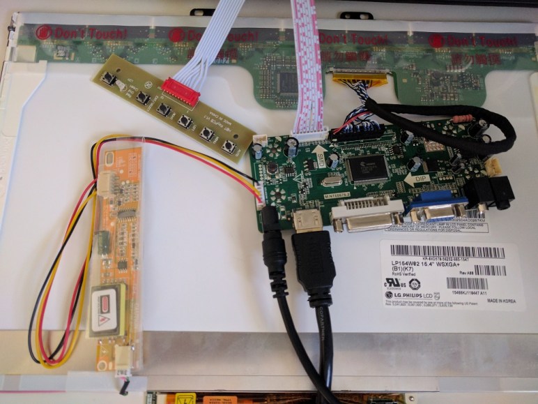
 Once the LCD panel and matching frame had been salvaged from the laptop, it’s time to build an enclosure to hold it and the associated driver board together. Since this was only the first draft, I was not very aggressive about packing the components tightly. It’s merely a simple big box to hold all the bits checking to see if I have all the mounting dimensions for all the circuit boards correct.
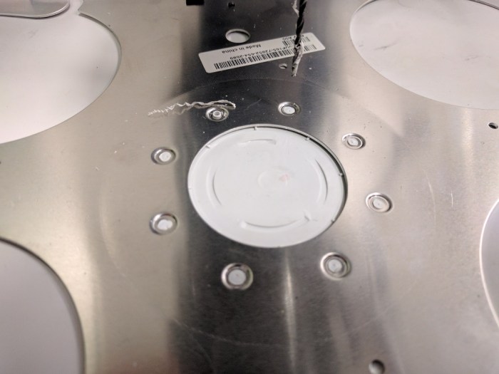 My Luggable PC display was a LCD panel I had salvaged from an old laptop, which I’m doing again for this external monitor project. When I pulled the Luggable PC panel out of the old laptop, I left most of the associated mounting hardware behind. During the Luggable PC project I wished I had also preserved the old mounting hardware.
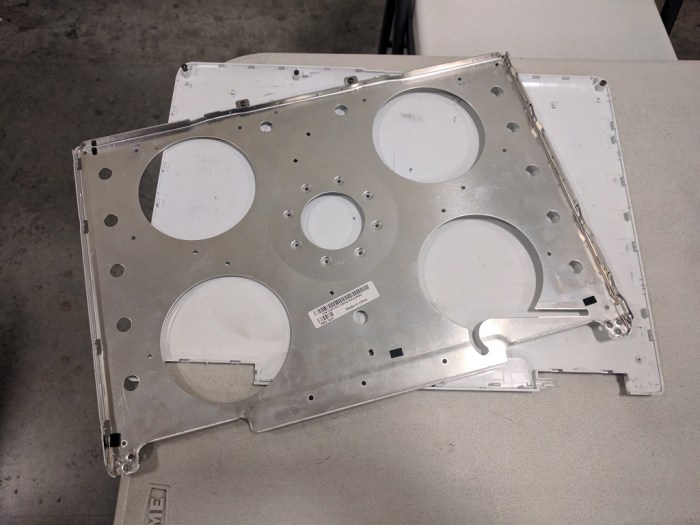


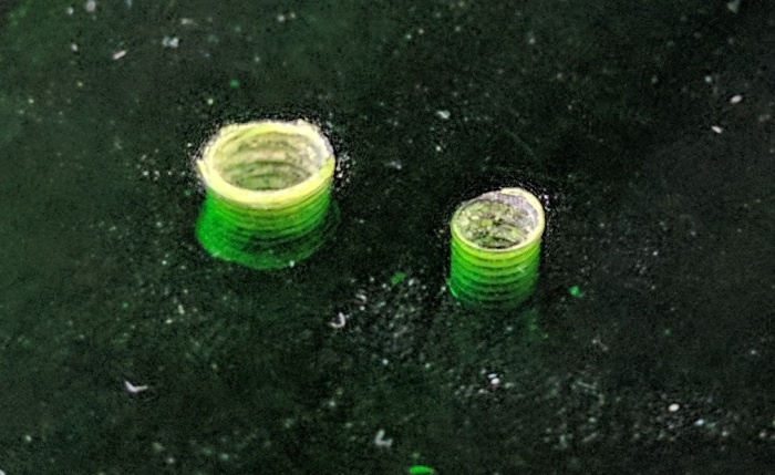
 In the previous post, the laser cutter kerf was successfully compensated, admittedly in a way that left plenty of room for improvement in the future. This post will look at a different challenge of building with acrylic: variation in thickness of acrylic sheets. So far experience showed different sheets of “6 mm” acrylic can actually be anywhere from 5.31 mm to 6.03 mm.