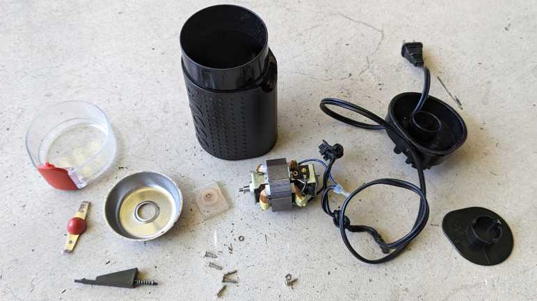
I took apart another low-end coffee maker and it was much like the first one I took apart. This theme continues with the next teardown: Bodum’s coffee grinder model 11160-3.
At its core, it is a blade spun by an electric motor to chop coffee beans into smaller pieces. From that perspective it isn’t terribly different from the Hamilton Beach 80344 I took apart earlier. But there are small differences in execution and the Hamilton Beach seems to be the better thought-out device.
The first of many examples is their power cord management. The bottom of the Hamilton Beach grinder is a knob that we can turn to reel in the power cord into a clever and compact mechanism. This Bodum grinder just has a wind-it-yourself slot for power cable.
The silver product information tag displayed the following information:
designed by bodum in switzerland
Assembled in China
Model no. 11160-3
Voltage 120V~60Hz
Power 150W
CONFORMS TO UL STD. 982
CERTIFIED TO CSA STD. C22.2
No. 1335.1 & 1335.2.14
In addition to power cable management, the controls are different. The Hamilton Beach grinder had a small circuit board for adjusting coarseness of the ground by controlling motor power. This Bodum grinder is an on/off operation.
The Hamilton Beach grinder also had a discreetly hidden safety switch that requires the lid to be installed before the motor could spin up. This Bodum grinder has a single switch pulling double duty. To activate that switch to turn the motor, the lid must be placed on the device (safety measure) and the red button mounted on the lid must be pressed (user intention.) It’s a clever way to reduce parts count without compromising safety, but they got too smart for their own good. Being the lowest recessed point, it is easy for coffee grounds to get stuck in that space. And because the button is mounted on the lid, its position varies somewhat due to manufacturing tolerances. Meaning it is possible to place the lid securely on the device yet have a misaligned switch pin that would not work when pressed. Both scenarios frustrate someone who just got out of bed and is trying to get their morning coffee. This grinder’s previous owner had one such morning too many and banished this grinder to my teardown pile.
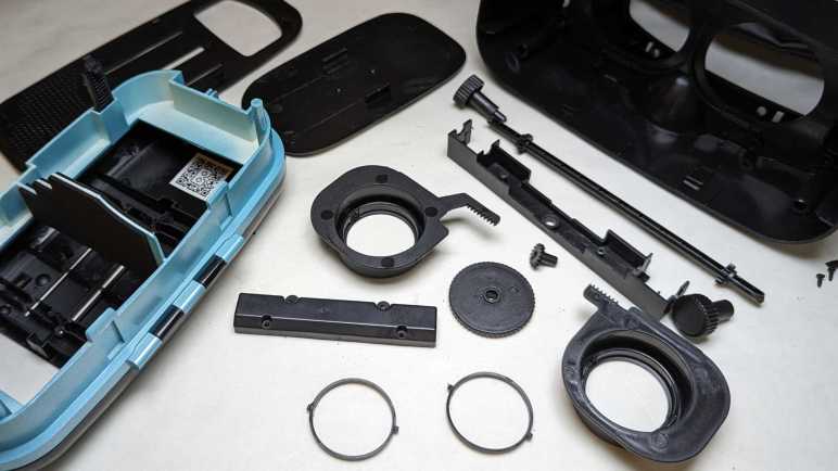
Unspooling the power cable unveiled three easily accessible screws.
Removing that trio loosened the base, but that was only a partial disassembly. The blade is still installed on the shaft. With the grinding bowl still between them, a lot of parts are still stuck. I need to remove the blade, but I don’t see a way to hold the motor shaft still. The Hamilton Beach grinder motor had a simple slot cut in one end so a flat-blade screwdriver could keep the shaft from rotating. But the bottom end of this motor shaft is not yet accessible.
The answer is a pair of screws hidden under the power cable spooling mechanism. Once I removed the bottom panel (one of three clips did not survive the process) I could free the motor.
A-ha, there’s the motor shaft and the slot I needed to release the blade.
It is possible to disassemble the motor further, but I thought I’d keep it intact for now. Here’s a mostly disassembled chopping-type coffee grinder for contrast against a burr-type coffee grinder.
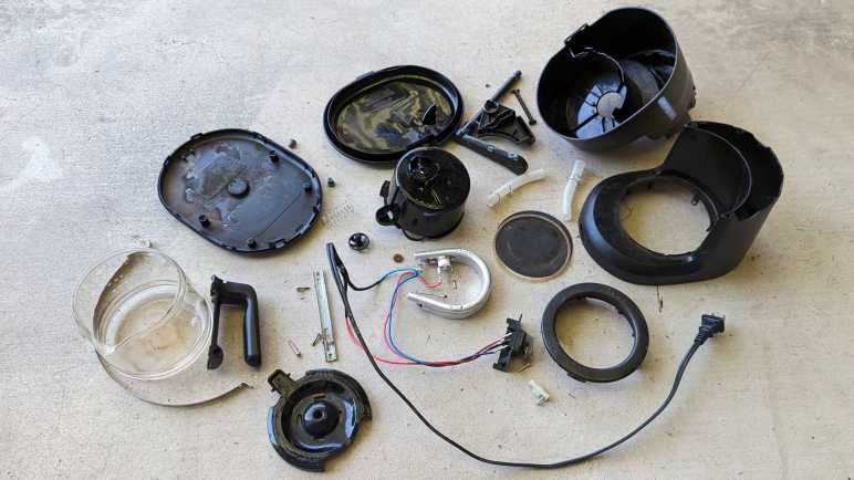
I’ve taken apart my retired phone VR headsets, so I’m moving on to retired appliances. This 5-cup coffee maker model number BVMC-SC05BL2-1 is the smallest and least expensive unit in Mr. Coffee product line. A direct counterpart to the Black & Decker DCM600B coffee maker I took apart earlier. I expect a machine with broadly similar implementation, as they’re both just need to make some coffee while being simple enough to be sold for under $20 USD.
This specific unit could still perform its core duty of making coffee but was retired due to failure of a convenience feature.
Here’s the coffee maker with its top open, showing the filtering tray. It is sitting under the hot water spout which pivots out of the way.
At the bottom of the filtering tray is a spring-loaded mechanism aligned to the top of the carafe.
When the carafe is present, it pushes the mechanism upwards allowing coffee to drip through. If we remove the carafe while coffee was still brewing, this valve is supposed to close. This will temporarily stop the coffee from dripping, allowing a cup to be poured before the brewing is done.
After years of use, the soft (silicone?) seal has degraded and could no longer stop the flow of coffee. This meant coffee kept dripping when that early cup is poured, making a huge mess on the hot plate. The only way to avoid that is to wait for all five cups to finish brewing before pouring some coffee, and that was deemed unacceptable by its owner and thus was retired and given to me for teardown.
Valve mechanism came apart easily. Now on to the rest of the machine.
I was surprised to find a tri-wing security screw here. The previous coffee maker teardown also saw a security fastener of a different type. I don’t know why both these companies felt simple basic bargain-priced machine justified security fastener protection.
Aside from those two screws, the bottom was held by plastic clips that could be undone. With the bottom removed, we can see some of that coffee that flowed past the worn valve and sizzled onto the hot plate has made it to the bottom of the machine. The following information was stamped on the bottom:
Mr. COffee
SUNBEAM PRODUCTS, INC.
BOCA RATON, FL 33431
Coffee Maker / Cafetiere
Model / Modele: BVMC-SC05BL2-1
650W 120VAC 60Hz
HOUSEHOLD USE ONLY
USAGE DOMESTIQUE SEULEMENT
DO NOT IMMERSE IN ANY LIQUID
N'IMMERGER DANS AUCUN LIQUIDE
Made in China / Fabrique en Chine

UL LISTED E236106
The entire electrical circuit of this machine. Power cable leads to a power switch, which leads to a heating element controlled by a thermal switch.
One novelty is the ball check valve. It was a separate component installed in the water tube on the Black & Decker machine. This machine molded the valve into the top half of the machine reducing parts count and assembly steps.
There were other minor differences, but I felt the molded-in check valve was the most novel. For the most part both machines were indeed nearly identical implementations of the same concept. I can say the same for the second coffee grinder I took apart.
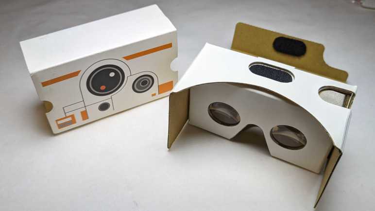
My Mattel View-Master VR headset was the last out of four phone-based VR headsets I retired and intended to take apart. I have one more that I’m going to spare this round of teardown:
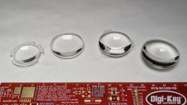
I disassembled those four headsets to see four different variations on the Google Cardboard concept. This BB-8 themed unit is an actual Google Cardboard made of cardboard. Except for the lenses, naturally, which will eventually be harvested as I did the other four.
When researching in preparation for this teardown series, I read up on Google’s specification for Cardboard lenses. I had expected all of those headsets to have identical lenses, but I was wrong. These four headsets had four distinctly different lenses with different diameters and thicknesses. I salvaged them without a clear idea of what I would do with them. I think eight identical lenses would have some interesting possibilities, certainly more than four pairs of distinctly different designs which is what I have on hand now.
I don’t know enough about optics to compare similarities vs. differences of optical characteristics of these four lenses. But I know they do fundamentally similar things. These headsets place a phone screen close to our face, far closer than we can comfortably focus our eyes without presence of these lenses. Putting the phone close also lets the screen fill our field of vision. What can such a lens be repurposed for?
My first tentative idea is to build a small loupe out of one of these lenses, giving me a workbench tool to inspect details in teardowns. A quick test just by holding it up to my eye seems to support this idea. The next idea was to see if I can build it into a magnifying (“macro”) lens for my phone camera. A quick test worked only to a very limited extent. I see a few magnified details within a tiny cone of clarity in the center of the camera’s field of view, leaving the rest of the image unusable. I need to learn more about optics before I can diagnose what went wrong with that idea. In the meantime, I return to tearing down stuff I do understand.
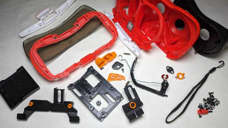
There were many different variations on the Google Cardboard VR viewer concept. The Utopia 360 tried to fill out a long list of features but could not ultimately deliver. On the opposite end of the spectrum was View-Master VR. Functionally this headset is just a basic viewer, but well-implemented in sturdy plastic instead of cardboard. (Mattel has some expertise with making sturdy plastic toys, to put it mildly.) Like the rest of the Google Cardboard ecosystem, this product has been retired but its support page is still online for the moment.
This was my favorite headset for basic Google Cardboard experiences. Its phone holder mechanism worked well, and the screen-tapping mechanism was reliable. But its time has passed so it is teardown time.
There is no head strap with this headset: this was intended only for short handheld experiences just like the original View-Master was. Such intentions also meant there were no provisions for a USB power cable nor for headphone wires. No matter, I had cut my own slots for power and sound.
Removing four screws freed the phone holding mechanism.
A few more screws and it comes completely apart. I didn’t notice anything that made me say “A-ha, that’s why this holder worked so well!” The reasons must be more subtle or in details that I lack the knowledge to recognize.
A few more easily accessed screws freed the front panel.
Going further was a challenge. I removed all the fasteners I could access but nothing budged. I decided three important screws were hiding under plastic caps. Prying at them didn’t accomplish anything, they were either a precise friction fit or glued in place.
Taking the destructive route, I pulled out the drill. It turned out they weren’t just thin caps — they were long plugs that go all the way down to the screw. The tricky part is stopping the drill before it destroyed the Philips head because I need that to loosen the screw.
That process got a little messy, but it accomplished the objective.
After I cleaned up the mess, I could get a good look at the screen tapping mechanism. It translated the trademark up-down View-Master lever arm motion into a front-back screen tap. I was surprised there’s no pivot point for the fake lever arm motion. That path was purely dictated by a curved slot molded into orange plastic. This is a clever bit of mechanical design.
Electrically, there’s a wire connecting the black squishy screen-tapping nub and a small piece of black plastic in the middle of the lever. Both of these black plastic pieces had a small amount of electrical conductivity: my multimeter measured several thousand Ohms of resistance across a distance of 2-3 millimeters. Apparently, this is enough to conduct user finger to trigger capacitive touch screen. The rest of the plastic are electrical insulators or at least show up as open circuit in the multimeter.
Looking at this design, I wonder why the long black L-shaped arm isn’t made of the same marginally conductive plastic. Surely that would be cheaper than adding the parts and cost of that wire? Perhaps it is not conductive enough to trigger capacitive touch, or perhaps that material lacks mechanical strength required.
Removing the final few screws allowed the red main plastic body to separate from black soft plastic of the rear section. Plastic lenses were held between these two parts.
I’m sad I didn’t really learn anything from the phone holder as I have project ideas that would benefit from an effective phone holding mechanism. Seeing another implementation of capacitive touch is also informative, but I don’t know if I can turn any of it into applicable skill. Still, I had fun seeing how this sturdy viewer was put together and (aside from those three caps I drilled out) relatively easy to take apart.
Despite being the largest and sturdiest of my four disassembled phone VR headsets, this Mattel unit actually had the smallest and thinnest lenses of them all. I’m not quite sure what that means yet.
Out of all the phone-based VR headsets I’ve tried, this Utopia 360 has the best spec sheet. It’s got variable focal distance adjustment like Samsung Gear VR. It’s got a Bluetooth remote control like Google Daydream. It even has interpupillary distance (IPD) adjustment, an appreciated but rare feature that I didn’t get again until recently with my Valve Index. But spec sheet bullet points aren’t everything. Lack of software support for many of those features, combined with a weak mechanical design, sabotaged this ReTrak Utopia 360 Virtual Reality Headset with Bluetooth Controller (Model ECVRC)
The generic phone holder mechanism didn’t work for my phone, so I replaced it with a more reliable phone-specific bracket as one of my earliest 3D printing projects.
Now that I am retiring the headset, I’m going to remove my old project on my way to taking everything apart.
With my custom holder removed, I can access the clips holding this front panel together.
Taking the front panel apart, I finally have confirmation that those ventilation holes we can see in the front are just useless, as they were blocked by the next layer.
Implementation of focal distance adjustment is far simpler than Gear VR’s implementation, with a single axle rotating a pair of rack and pinion mechanisms. But this is a finicky thing that didn’t work as smoothly as Gear VR’s implementation.
Removing the center cover did not free the rotating axle: it is still held by either side.
But it did allow the axle to flex enough for me to pull off the front. I still couldn’t get to all of the remaining fasteners, though. The focal distance adjustment axle remained stubbornly in the way. My search for fasteners or retention mechanisms came up empty, I concluded it was glued in place.
Two snips with a diagonal cutter and the axle is no longer in my way. I could access all of the remaining fasteners now.
One set of fasteners held the rear of the headset in place.
The other set of fasteners held down the IPD adjustment mechanism: a single pinion gear moving the two eyepieces in opposite directions.
Both eyepieces were removed so I could salvage the lens, held by a retaining ring with two tabs.
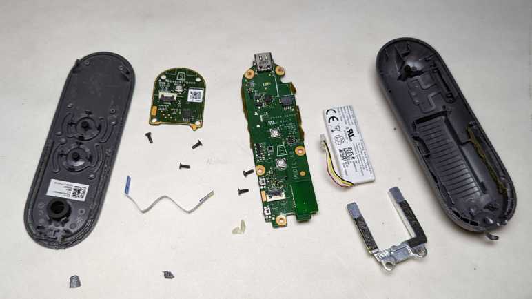
With the headset disassembled, I turn my attention to the controller. Which also looked great on the spec sheet but would frequently lose connection to my phone and felt cheaply made in the hand. (I suppose because it was.)
It runs off a pair of AAA batteries, which I forgot about and left them in this controller and now it is damaged from battery leakage. What matters today for disassembly is the pair of fasteners visible in the battery compartment.
The top piece came free easily, uncovering the button array and a two-axis joystick mounted on the mainboard’s top. A few screws held the mainboard in place.
Removing them freed the mainboard, so we can see the trigger switches board held by another pair of screws.
Removing the trigger button board for a closer look, I see a very straightforward implementation.
Mainboard backside. The biggest chip has the following markings:
This controller was easier to take apart than Google’s Daydream controller, with no glue holding things in. If it had a piece of weight like Daydream did it might feel more substantial in the hand, but that would not have improved the tactile feedback of its buttons.
Mechanically speaking, this headset was more complex than Daydream headset and simpler than Gear VR. Too bad it didn’t work as well as its spec sheet suggested. I think it’s because it tried to do too much. In contrast, Mattel View-Master VR keeps its feature scope constrained and does its job well.
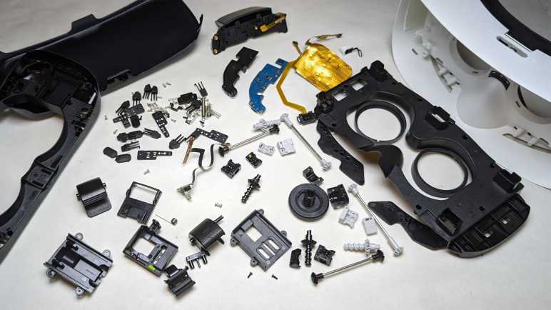
While Google specified a handheld controller to their Daydream VR system, Samsung chose a different solution to Google Cardboard’s limited interactivity: they added controls to the side of their Gear VR headset. Reading that description, I thought they just added a single circuit board with a few buttons. The reality was far more mechanically complex, resulting in a far higher parts count than I had expected.
This is a Samsung Gear VR SM-R322, compatible with a half dozen Samsung devices including the Galaxy S7 phone. I bought this as a present for a friend who had a Galaxy S7. Years later, he retired that phone and donated it to my electronics tinkering. (After resetting and wiping his personal data, of course.) He also returned my present, still unopened.
Since Samsung has already shut down their Gear VR experiment, there wasn’t much I could do with it except to take it apart to see what’s inside. I plan to keep the lenses and nothing else.
Gear VR side controls are dominated by what looks like a four-direction pad but is actually a capacitive touchpad. Off to the side are physical tactile up/down buttons (feels like volume control?) and a back button.
An adjustment wheel at the top changes the distance between its lenses and the device screen. (Focal length.) I estimate its range of motion to be roughly one centimeter. Its implementation turned out to be more complex than I had expected.
The face gasket was held with hook-and-loop fasteners. Peeling it off didn’t reveal any fasteners or likely hiding places for them.
Pop off the front cover for a look the device holding mechanism.
Headset-to-device communication is done via this micro-USB plug, which can slide between two positions indicated by a green dot over either A or B. Most of device holding force is supplied between this clamp and its opposite number, which didn’t have a USB plug. Helping to keep the device in place are small bumpers at each corner.
A thin rubber pad adjacent to those bumpers hid fasteners, one for each corner. That hole next to the Philips-head screw is a part of the focal length adjustment mechanism.
Two additional fasteners were in the middle, hidden under a sticker.
Once undone, the device holder tray can be flipped open though it is still connected to the headset by this cable for USB connection and two of the side buttons. A flexible cable is required to bridge a gap whose size varies based on the focal length adjustment.
Freeing the USB cable required removing a cover to access all electrical connections to the mainboard.
Then the spring-loaded USB connector assembly could be freed and disassembled.
Looking inside the device holding tray, I realized the corner bumpers were more sophisticated than I had expected. I thought each corner was a single piece of squishy rubber, but it’s actually three distinct and individually spring-loaded piece of plastic. Multiply this out to all four corners and we end up with twelve sets of bumpers and springs.
Back to the headset main body, removing its mainboard allowed us to open it up to see the focal length adjustment mechanism.
Rotational motion from the top adjustment knob is transmitted via a series of gears and shafts to all four corners.
A close-up look at a corner mechanism translating rotational motion to linear motion.
Under the mainboard is a piece of black plastic that I had expected to host the capacitive touch pad, but it only had the back button. I can see four wires in this cable, which is double the amount I expected. A simple switch should only need two?
The capacitive touchpad is actually glued to the inside of the enclosure. Its control chip has the following markings:
The glue was tenacious and thus touchpad was damaged during removal. I don’t recall ever seeing this pattern in a capacitive touchpad before.
The final bit of electronics is a sensor that sits looking at the user’s forehead. Its location implies an optical proximity sensor to see if it is being held up to the user’s face.
The lens retention mechanism has three little clips that need a little push to release the lens.
There’s nothing fundamentally complex about adding side controls to a Google Cardboard-style headset. But when we add mechanisms to securely hold phones in a range of sizes plus the ability to adjust distance between lens and screen, we end up with a mechanically complex device with a high parts count. It worked really smoothly, though, perhaps all those parts were necessary for proper operation and going with a low part count design hurts functionality.
User interactivity in Google Cardboard was limited to a single button tapping anywhere on screen. Google decided to address that limitation with their follow up Daydream VR by adding the requirement of a handheld controller to go with the Daydream headset as a complete system.
The small text imprinted on the back of the controller included an FCC ID because this is a Bluetooth device operating over airwaves. Curiously, a search for A4R-D9SCA came up empty on the FCC ID search site. Looking around the internet for other resources, I found a teardown posted by SlashGear. I was disappointed (but not surprised) this device is largely glued together and will be more difficult than the headset to disassemble.
Fortunately, I have the freedom of not caring if I break it, so I started prying. Half of the controller (the palm end) was indeed held by glue. The other half (touchpad end) is designed to flex and so we can click the touchpad, thus it was only held by two clips that allowed a small range of motion.
Focusing on the top panel circuit board, I see a small white tactile button in the middle for clicking, and a chip with the following markings:
Curious what the other side looked like, I used my flush cutters to cut away melted plastic rivets holding the circuit board in place.
We see a grid of diamond-shaped metal pads for the IQS525 to sense our finger position.
The mainboard is held very securely. Not just by several screws, but also by glue. While the glue is brittle and easily cracked, it still put up quite a fight.
By the time I freed the mainboard, it was very bent.
Under that board is the battery and a small piece of metal that couldn’t be a heat sink as it doesn’t touch any of the chips. It’s probably just to add heft to the controller right in the middle of where our palm would be. It is mainly held by some double-sided tape, but it is also in contact with that glue. It takes a bit of effort to pry it free.
The battery is held by a stretch-release adhesive strip, but I have yet to develop the fine touch needed to make those strips work for me. I pulled too hard on this one and it broke. Fortunately, it released enough for the battery to come free. Aided by the fact the enclosure designed a bunch of ribs in the battery tray for a much smaller contact surface than if the enclosure had a smooth flat base. It’s curious we have these ribs and stretch-release adhesive features for easy battery removal, yet it is trapped under a circuit board that was glued in place. Some design criteria must have changed partway through development.
Since this small battery saw barely any actual use or much abuse during removal, I am willing to consider repurposing it in a future project.
Due to the copious amounts of adhesives and glue, this controller was annoying to take apart. In practice it is likely to be impossible to repair as well. The battery was far more difficult to remove than it really needed to be. I expect very few of them have been properly disposed or recycled after retirement.
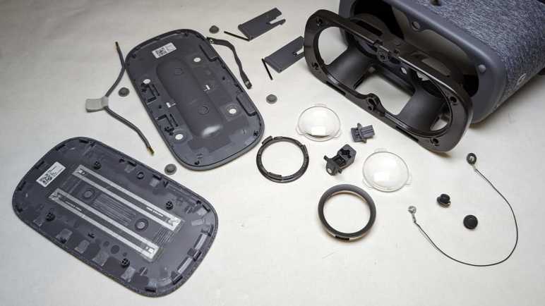
I’ve decided to dispose all of my 3DoF VR headsets, which I haven’t touched since upgrading to 6DoF VR equipment. They will be taken apart to see how each manufacturer approaches building such a headset and extract their lenses for potential future projects. First up: a Google Daydream VR headset.
Daydream was Google’s effort to evolve from Cardboard. One major difference is the addition of a handheld controller. It has an accelerometer within for 3DoF tracking, a small round touchpad, and four buttons: two on the face and two on the side. Making it a required component means Daydream apps can take advantage of far more interactivity than Cardboard’s single tap.
Another evolution for user-friendliness were the two black nubs towards the center. They make contact with phone screen and register as two touch points. The Daydream app will read their position and adjust display image for proper alignment with the headset, using software smarts to eliminate one user headache. Pretty clever!
The easiest item to remove was the face gasket, held with hook-and-loop fasteners for cleaning or replacement.
Once removed, seven small Torx (T5) fasteners are accessible for removal.
The retaining mechanism for the front panel is also now accessible. To release them, disconnect the spring and press retaining hooks inward.
Front panel hinges can then be slid free.
I thought there might be fasteners underneath rubber nubs in the front panel. I was wrong.
Brute force prying released the extensive set of plastic clips holding two halves together. Not all of the clips survived this process.
Once those two halves were separated, everything else inside the panel came away freely. Hinge pins, elastic holding straps, etc.
As soon as the phone was inserted into this Daydream headset, it knew to go to Google Play store and download the appropriate Google app. (Another user-friendliness advancement.) I wondered how that was accomplished and the answer are these RFID strips made by Identiv.
Back to the headset, there was one more Torx fastener hiding in a different place and orientation from all the others, up near the top of our nose.
Its removal frees the hook at the top of the headset.
Which then frees up the optical frame. I was surprised to see a length of wire for electrically connecting the two screen alignment nubs.
I’ll keep the wire — and the two nubs — in case I want to play with capacitive touchscreens.
The lenses are clipped in at three points with a simple mechanism.
Tearing down a relatively simple AR beacon was the final step (after the headset and the lightsaber) of dismantling Lenovo’s disappointingStar Wars: Jedi Challenges game for disposal. Since I was still in a teardown mood, I decided to continue dismantling my collection of phone-based headsets. I have quite a collection and, in hindsight, they’ve all been money wasted. Those devices could only react to motion in three degrees of freedom and never approached the immersion of real VR headsets that can track six degrees of freedom. I packed them away after getting my first 6DoF headset, thinking I might find a way to do something creative with the phone-based headsets.
I never got around to devising interesting projects with Google Cardboard (and derivatives) and it’s not going to get any easier in the future. Google officially killed Cardboard in 2021, but by then it was merely a formality. Derivatives (and wannabe successors) like Samsung Gear VR and Google Daydream were abandoned even earlier. With official support discontinued, software support for any potential project ideas also faded away. The first-party SDKs have either gone stale or have disappeared. Third-party support is no better, being removed from tools like Unity and Unreal. And finally, infrastructure support like Samsung Gear VR Store and Google Daydream app have been taken offline. If I want to write code for Google Cardboard/Daydream/Gear VR I would almost have to work on my own scratch, like another long-past-its-prime hardware platform Windows Phone. But this would actually be even more difficult, because I don’t know how to work with these lenses in software in terms of 3D rendering projection math.
Therefore, using them as VR headsets would require more effort than I’m likely to spend. Keeping them intact as VR headsets consume a lot of space with no good payoff I can foresee. Looking at this very simple design, the only reuse possibility I can imagine are those lenses in a non-VR application. At the very least, a bag of salvaged lenses would occupy less space than a bag of obsolete and abandoned VR headsets. With this line of thinking, my phone-based VR headset purge begins. First on the workbench: Google Daydream VR Headset.
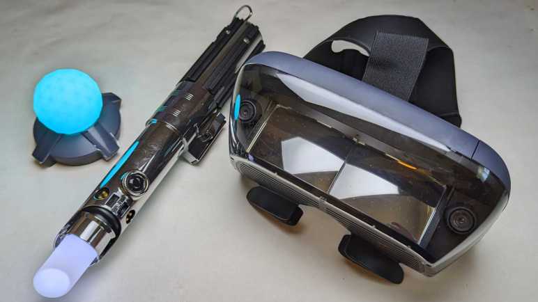
A shiny plastic “lightsaber” is the main peripheral of Star Wars: Jedi Challenges and it was fun to take apart. There was another peripheral in the box, a glowing ball beacon to support certain scenarios.
In this beacon’s base is a three-position switch. Center position is off, and moving to either side would illuminate the soft white translucent sphere. One position gives us cyan, the other position magenta. Given this behavior, I guessed the lowest-cost implementation would be a strictly analog system with LEDs connected to a resistor network. Time to open it up and see if my guess is correct.
This beacon uses AA batteries instead of lithium-ion rechargeable.
Product labels live in the AA battery tray.
Unlike the lightsaber, there is no FCC ID here meaning it doesn’t communicate with the phone or the lightsaber over radio waves. There is no USB port or any other hardwired communication. There might possibly be some kind of communication via lights or sound.
Two Philips-head fasteners live under those stickers. Remove those stickers, then two screws, followed by a few plastic clips to separate top and bottom halves.
Wow, my guess of “a few LEDs and a few resistors” was very wrong. This is a surprisingly complex mainboard. I’ve already ruled out radio wave or hardwired data communication. Looking on the board, I couldn’t find anything I recognized as a light sensor for optical communication or a microphone/speaker for audio communication. If this is completely passive, why all this hardware?
Instead of a cyan LED and a magenta LED, in the middle was a full RGB LED capable of arbitrary colors. The surface mount component itself appears identical to the unit illuminating the tip of the lightsaber. Full color capability is not a huge surprise in itself. But in the absence of external communication, how would it know to display another color?
I can see the following markings on the chip in the corner:
S033
PHVG
725Y
Searching on these designations, my first hit was a question about an electronic cigarette. I know nothing about vaping hardware, but I had not expected them to require microcontroller smarts, either. (I’m surprised twice within a short span.) The chip was identified as the STM8S003F3 and a look in its datasheet confirmed the device marking for UFQFPN20 packaging has a first line of S033 matching what I see here.
The STM8S003F3 is a relatively simple 8-bit microcontroller with eight kilobytes of flash program storage and a single kilobyte of working memory. These are modest specs, a fraction of the ATmega328P at the heart of an Arduino Uno, but it is still overkill for a device that just shines a LED in one of two colors.
This beacon must be capable of far more than what I’ve seen it do. Which is highly likely, given my short time spent actually playing Star Wars: Jedi Challenges. But looking at the hardware in front of me here, I don’t see how it could interact with the rest of the system to unleash said capability. Still, it was an interesting look inside. I’m enjoying this particular streak of teardowns so I will continue with the rest of my phone-based headsets.
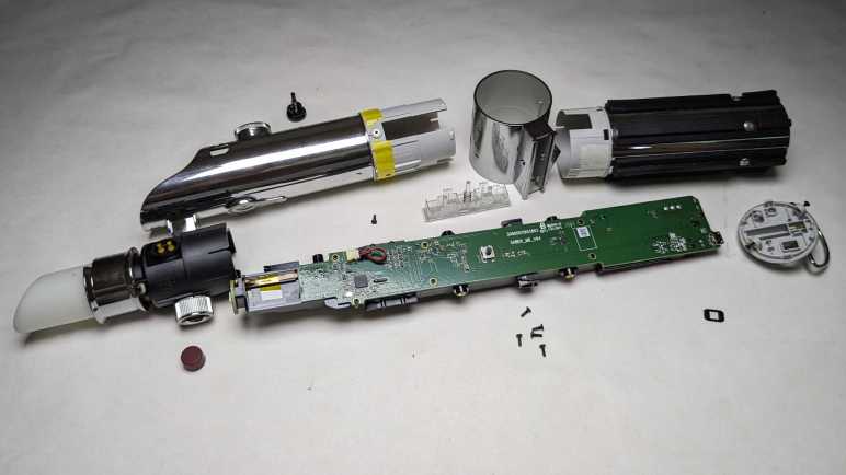
I was disappointed by Star Wars: Jedi Challenges as a product, thankful I only paid clearance price for it but that also meant I couldn’t demand a refund for a lackluster experience. No matter, I still got enjoyment by taking apart its Lenovo Mirage AR headset to learn how it worked. And now I will take apart the main peripheral: Rey’s Lightsaber.
Production promotion proclaimed this to be a “collectible-grade” lightsaber. I have no idea what that is supposed to mean. Perhaps Disney licensing department has defined categories for their merchandise, but as far as I’m concerned, it’s just marketing fluff.
Fluff aside, I will give it credit for being far more detailed than I had expected. A high-quality shiny chrome finish throughout the device gave it a much more premium look than cheap Halloween costume lightsabers made out of dull gray plastic pretending to be metal. Chrome finish aside, though, this is sadly still just plastic pretending to be metal.
This saber talks to the phone inside the Mirage AR headset via Bluetooth. (When powered on, my phone can see it as a Bluetooth device named “Rey’s Saber”.) FCC paperwork is required for all consumer products sold in the United States that transmit and receive data over any kind of radio frequency including Bluetooth. Such data is public record so armed with an FCC ID (O57AR7651N in this case: O57 is Lenovo, and AR7651N is the Jedi Challenges product) we can go to FCC’s ID search page and see what has been filed for a product. This frequently includes photos of the product in disassembled form, a very useful guide for teardowns. Nothing like a detailed iFixit teardown guide, but we can see the major pieces and look for fastener locations. It cuts down on the fruitless hunting, especially when the fasteners are well hidden, which they were for this saber.
Thanks to the filing document “TempConfidential_Internal Photos_Rev1” PDF, I could see a fastener lined up exactly at the location of a nonfunctional button. It was held with double-sided tape and could be removed to access the Philips-head screw underneath.
Freeing that single screwed allowed the tip to slide out.
If somebody wanted to repurpose this lightsaber as a costume prop, it should be easy to replace the soft translucent white tip with something more appropriately mechanical in appearance.
That translucent white tip is illuminated by this surface mount component.
Backside of this small circuit board indicates it is a trio of LEDs in a single surface mount package, controlled by four wires: one each for green, red, and blue and a common ground.
Returning to the FCC filing PDF, I saw the base had two heat-set inserts to accommodate machine screws and the picture quickly guided me to where they were hidden underneath glued-on rubber pads.
Remove those two to release the base.
Rubber pads hid two more screws.
Removing them allowed the grip to slide off.
Things got trickier from here. Looking at filing pictures I could see a screw is hidden underneath this button, but I couldn’t see a graceful way to access it.
I ended up prying against the four little claws inside the saber in order to release the button, then I could access that screw.
Then I could slide off the center ring section, exposing three final screws holding the exterior in place. Once removed the exterior could slide a fraction of a millimeter but it is not yet completely freed.
A bit of wiggling pointed to this button as the culprit. This is a functional button and that knurled surround hints at a ring I could remove, but that was an illusion. I saw little plastic pieces inside and thought I should pry them free just like I did the previous button.
That was a mistake. Prying the button free damaged both it and the socket it resided in. Now that I could look at its distorted shape, it appears to be designed to be uninstalled with a quarter-turn counterclockwise. I have no idea how I would grip this button (while installed) solidly enough to perform that quarter turn overcoming the little nub designed to resist accidental turning. Maybe a suction cup? I don’t know. What I do know is that it’s now too damaged to be reinstalled with a quarter turn clockwise. I had hoped to tear down this saber nondestructively in case I have an idea for repurposing it, but I have passed that point of no return. Ah well.
Setting that disappointment aside, I can look at saber internals. It is a very thinly populated board with few components.
The black plastic backbone securely holds an electric motor with an eccentric weight on its shaft. This would be good for shaking the saber in our hands to signify battle action.
The black plastic frame also holds this piece of metal that does nothing except add heft to the saber so it feels appropriately substantial when picked up.
Given its weight, I had expected a chunky array of NiMH or even NiCad rechargeable batteries inside, but it’s actually a slab of metal and this thin little lithium-polymer pouch. I would have said it was undersized to drive the tactile feedback motor but I’m no battery engineer.
Several test points are visible adjacent to the battery directly behind the microcontroller. I assume Lenovo/Disney locked down the nRF52832 so we can’t flash our own firmware. Maybe a skilled ARM security researcher could find a way in via glitching the power supply for fault injection, but I don’t know how to do that. The locked-down nRF52832 can be unsoldered and replaced with an unlocked chip, but such tiny BGA chips are also beyond my current skill level.
I didn’t expect to find much in the way of reusable components, and I didn’t. I was surprised at the robustness of the mechanical construction. I had expected to find a single screw and have it fall apart in two halves. I’m glad I found the FCC filing PDF, which made this teardown go smoother and almost nondestructively. Now for a change of pace, I’ll take apart the final hardware component of Star Wars: Jedi Challenges, a simple illuminated AR beacon.
The Lenovo Mirage AR Headset (bundled with Star Wars: Jedi Challenges) was a huge disappointment, now I’m going to extract what entertainment I can from tearing it down. From a mechanical engineering perspective, I was very impressed by what I saw. Unfortunately, robust mechanical design could not overcome fundamental product weaknesses.
Before I started the teardown, though, I was curious how it would enumerate as a USB device. I plugged it into a computer running Ubuntu and here’s what got dumped out via dmesg:
usb 3-1: new full-speed USB device number 3 using xhci_hcd
usb 3-1: New USB device found, idVendor=1f3b, idProduct=1000, bcdDevice= 2.00
usb 3-1: New USB device strings: Mfr=1, Product=2, SerialNumber=3
usb 3-1: Product: AR Head Mounted Device
usb 3-1: Manufacturer: Lenovo
usb 3-1: SerialNumber: 101215-0073
hid: raw HID events driver (C) Jiri Kosina
usbcore: registered new interface driver usbhid
usbhid: USB HID core driver
hid-generic 0003:1F3B:1000.0001: hiddev1,hidraw0: USB HID v1.11 Device [Lenovo AR Head Mounted Device] on usb-0000:00:14.0-1/input0
Looks like it conforms to USB HID standards, but as a “raw” device not obligated to conform to any common peripheral. Since it doesn’t try to pretend to be something common (say, a mouse) we have to know its raw USB communication format in order to communicate with this device. If I still had the app installed on my phone, I could peek at its control schema using a USB reverse engineering tool like Cynthion (formerly LUNA). But I had neither. With my skill level and what I have on hand, I can’t do much except take it apart.
I started with the easiest removal: the head strap which was held by hook-and-loop fasteners.
Next was the phone caddy, the only other user-removable part in this system. Visible in this picture is the short USB cable for the headset electronics to communicate with the phone. I used this headset with a Google Pixel so this is the USB-C cable. The headset came with two other cables: micro-B for other Android phones, and a Lightning for Apple iPhones.
The caddy had to accommodate over a dozen different phones and thus had mechanisms to adjust for different width, height, and thickness.
Working to meet those requirements were a lot of intricate details in the design of these injection-molded parts. (Aided by a few inserts made of stamped sheet metal.)
Next to the caddy slot (and USB port) is a product information sticker.
Reaching the end of user-serviceable parts, I pulled out my iFixit Mako screwdriver kit and started removing fasteners visible on the bottom. (Center fastener was hidden under a sticker.) There were multiple different lengths of fasteners. Some were machine screws and some self-tap into plastic. But with one minor exception, I only needed a single screwdriver bit to drive them all. That must have been a conscientious decision by the mechanical engineering team and I appreciate their effort.
First plastic piece to be removed was the clear front piece, whose removal exposed several more fasteners.
Fasteners were also hidden under dark plastics on the sides, though these wouldn’t be important until a little later.
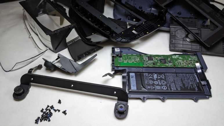
After removing every fastener I could find, the headset remains stubbornly sturdy. Flexing it in my hands failed to highlight any promising seams to pry against, so I started prying at every seam between different materials. The first clips to release were next to the side buttons.
Following those clips around the perimeter allowed the top to be released and unveil a circuit board and a battery. The circuit board is labeled with Legend_HMD_MB_PCB_V05 2017.08.10. I interpret this to mean: Legend = project code name, HMD = head-mounted display,. MB = motherboard, PCB = printed circuit board, V05 = fifth revision. Followed by date of August 10th, 2017.
Biggest chip on the circuit board is an STM32F205RE microcontroller, built around an ARM Cortex-M3. The next biggest chip is a LFE5U-45F 6MG285C Lattice Semiconductor FPGA. I assume the camera-based object tracking algorithm is implemented in this FPGA. I couldn’t find that specific part number on Lattice web site, perhaps it is an obsolete part? I was redirected to the page for Lattice ECP5 family so I guess it’s one of those. Most of the left third of this board is unpopulated, with footprint for at least one nontrivial BGA part. I wonder what they had planned for that area? That is near the trio of side buttons, perhaps they had plans for other headset designs with different side controls? One possibility is a touchpad and if so that BGA footprint might be a capacitive touch processor.
The bottom of the phone tray caddy area turned out to be a sticker I needed to peel off in order to expose more fasteners.
Once released, we could remove the louvered bottom as well as dark smoke colored side pieces.
Optical reflector assembly fasteners are now accessible.
The optical reflector assembly (laying upside-down in this picture) consisted of three pieces of clear plastic with semi-reflective coatings. One flat sheet spans the entire width, and two curved half-width pieces one for each eye. Looking at the geometry, I now understand how this works and I’m not impressed. I don’t know how much light the coating reflects and how much is transmitted, but using 50% as an example, this is what we would end up with:
Image from phone screen shines down to the flat sheet. 50% of the light is transmitted straight through and lost out the louvers in the bottom of the headset.
The remaining 50% is reflected to the two curved pieces. Of that original 50%, 25% is transmitted through and forwards, lost to the environment. The remaining 25% of that original light is reflected back towards the flat sheet.
The flat sheet reflects 12.5% of original light right back into the phone, where we can’t see it.
That leaves 12.5% of original phone screen light transmitted through the flat sheet into our eyes.
Only a small fraction of light makes it all the way to our eyes, no wonder everything was so dim! This reflector assembly is part of a recurring theme: it is mechanically sound with sturdy mounting, but robust mechanical engineering could not overcome a fundamentally inefficient optical path design.
Now that I understand how it works, I’m not terribly interested in keeping this optical assembly for homebrew AR headset adventures. Also, for accurate projection I need to know the curvature of those two half-width pieces and I don’t have that data. Reverse engineering that information takes knowledge of optics that I currently lack. Can I do something with this (or pieces of it) with the skills I have now? I’ll set this reflector assembly aside for a little bit longer while I think.
Resuming the teardown, I couldn’t find any fasteners holding down plastic pieces surrounding the camera. A little exploratory prying popped them loose: they were held with double-side tape.
Now I could remove the camera assembly. Two cameras are held at a precise distance apart by a metal frame, the only metal structure in the entire headset. Metal rigidity would be useful to maintain distance, but it also serves as heat sink for the pair of cameras.
A trio of Philips-head fasteners hold the camera to the frame. I had hoped for some identifying marks on the back of these cameras, but no luck. The only markers were on the thin ribbon cable. A QR code that scanned out to 8SSC28C19780AXYY7A55567 (no clue) and human readable text as follows:
MDG001-200
SUNNY
B1734
94V-0
2PE
E310562
Searching the web for that information, I learned 94V-0 is an UL standard for flame resistance and probably refers to the FPC (flexible printed circuit) substrate. “Sunny” probably refers to Sunny Optical, a Chinese company for camera modules. Lots of camera modules are listed on their website but I didn’t find a match for any of these numbers. The site had a section for VR/AR products, but the only listing is for an eyepiece lens. Sunny E310562 got a few hits on eBay for camera modules corresponding to other Lenovo products, which makes me feel like I’m on the right track, but they look very different. Not sure what’s going on there. I think I struck out.
The lens is removable. I don’t know enough about small cameras to recognize if it this was a standardized lens mount form factor or something proprietary. I removed the lens hoping to see some identifying markers inside. I saw the imaging sensor array, but no identifiers. This camera was significantly larger than OV2640 popular with electronics hobbyist kits and much larger than what I’ve pulled from phones and tablets. I expect this to be a very capable camera and it’s a shame I can’t repurpose it for robot vision or something.
That was a fun teardown and I learned more than I had expected, including an understanding of this optical reflector’s fundamentally flawed design. But I’m not done yet: this is part of Star Wars: Jedi Challenges and a Jedi needs a lightsaber.
I’m fascinated by the significant promise and potential of Apple Vision Pro, but I’m waiting to see real-world feedback. They would have to be very positive for multiple product generations (at the very least, a more affordable non-Pro edition) before I would consider pulling out my own credit card. The last time I paid money for an AR experience, it was on the opposite end of the spectrum that was barely more than an old school Pepper’s Ghost illusion.
This was the Star Wars: Jedi Challenges product, with a Lenovo Mirage AR headset as the main hardware component. With all hype and no substance, there was no follow-up to this now-retired product. The promised third-party software development kit never materialized. The lone app has been removed from app stores. Its main URL now redirects to Lenovo’s general website, though its product support page still exists for the moment.
My first experience with an AR headset were automaker promotions with Microsoft’s Hololens and I was impressed. Sometime after that, Star Wars: Jedi Challenges promotion hype machine started spinning. I was intrigued but skeptical. It cost a tiny fraction of a Microsoft Hololens so I knew there were compromises involved. It is built around a cell phone like all lackluster 3DOF VR headsets, but this headset adds a pair of onboard cameras with onboard processing hardware that sends data to the phone via a USB cable. Based on that description, it was possible there is enough hardware for a rudimentary AR experience.
The reality was disappointing. While we did have 6DoF tracking, it was restricted to the lightsaber peripheral, just barely good enough to draw a virtual lightsaber blade on the AR headset at a rate of (unscientific guess) 30fps. There was a clearly perceptible lag between our lightsaber movement and the glowing line onscreen. In addition to the lightsaber, the cameras could also track an external beacon. A squishy rubber ball with a colorful LED inside. Since it is a sphere, there was no meaningful orientation tracking as with the lightsaber, just position relative to the headset.
There was no further understanding of our environment and no tracking of the AR headset itself. Not even 3DoF tracking like in Google Cardboard. Kylo Ren is directly in front of us regardless of which way we are looking. If we are looking down, Kylo Ren is in the floor. If we look up, Kylo Ren is in the ceiling. As far as I can tell, the only reality this headset augmented was the lightsaber, drawing a lightsaber blade over a fixed and scripted experience projected Pepper’s Ghost-style in front of my face. As far as an immersive experience goes, this rated even lower than what we can get from Google ARCore.
The good news was that I didn’t waste too much money on this disappointment, as I had waited until these things were heavily discounted just so stores could clear them out of inventory. If I had paid full MSRP I would have definitely demanded a refund! The bad news is that, since I got them on clearance, there was no refund and no return. They sat gathering dust until recently as I decided to write up my VR/AR/XR experiences here. There’s no reason to keeping taking up space with this garbage, meaning now is a good time to take it apart before disposing of it.
I’ve had a lot of fun the past few years exploring virtual realities and I have my favorites. While researching buying a new headset I came across rumors that Apple might be entering this space. Those rumors have recently proven to be true and announced as Vision Pro. As is typical of Apple, they are focused on doing their own thing. In this initial set of announcements and carefully chaperoned press experiences, there has been no overlap between Vision Pro capabilities and any of the VR experiences I’ve enjoyed so far. In fact, out of all the press about this new thing, the one I found most informative is a CNet piece about what Apple has not expressed interest in doing with the Vision Pro.
What has been disclosed about Vision Pro hardware is extremely impressive, following many examples of Apple’s past hardware innovations. It was not a surprise the company that touted “Retina Display” would give us high resolution displays covering a wide field of view. Apple silicon’s power/performance leadership should easily outpace Oculus Quest while still maintaining power efficiency superior to PC hardware. And their Airpod experience should help engineer high quality integrated audio.
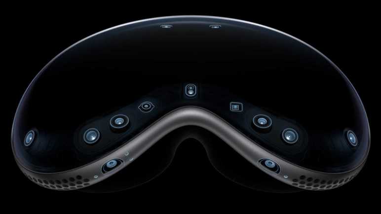
What I did not expect was the extensive sensor array built into the device highlighted in this image from Apple. The advertisement pitch is “precise head and hand tracking and real-time 3D mapping“. I expected some variation of the iPad Pro LIDAR scanner for Apple’s ARKit type capability, but Vision Pro goes far beyond baseline ARKit type functionality. I suspect there’s some headroom built-in for developers to explore usage scenarios Apple hasn’t even thought of yet. If some of these capabilities don’t pan out, they can be trimmed back in a hypothetical future affordable Vision non-Pro model.
Apple has clearly thought of a lot, though. One peripheral not mentioned is any type of handheld controller. All the hype is about how that sensor array can precisely track the user’s hands. Our eyes come into this as well, with gaze tracking inside the headset. Combining these capabilities, Apple has designed their own of interaction semantics free of handheld controllers. I’d be curious how well this works outside of Apple’s carefully curated introductory experience.
One design detail I appreciated was Vision Pro doesn’t try to accommodate eyeglasses. Every other VR/AR headset had to be larger and bulkier than they strictly needed to be, just so they can enclose a large space around potential eyeglasses worn by the user. For people without perfect vision (or unwilling to wear contact lenses) using Vision Pro means an additional financial commitment of buying lenses matching their prescription for installation inside the Vision Pro. Unfortunately, this also means I’m unlikely to get a quick trial experience of somebody else’s headset like I got with the Oculus DK2. I would have to find someone (1) willing to let me try their expensive Vision Pro, (2) have vision prescription close to mine, and (3) have similar spacing between their eyes. Not impossible, but I’m not counting on it.
Seeing how Apple’s Vision Pro doesn’t even try to compete directly against existing products, I’m happy to see Apple continuing to do their “Think Different” thing trying out new ideas. I eagerly await more information once Vision Pro gets in the hands of actual users and away from scripted Apple chaperones. That’ll give us a much better idea whether it is the initial groundbreaking product of a new category or a noble but ultimately doomed experiment. It wouldn’t be the first time an AR product ended in disappointment.
I’ve just upgraded my VR system to a Valve Index headset backed by a Dell XPS 8950, displaying graphics generated by a RTX 3080 and a Core i7-12700 feeding it data. I thought this was a good checkpoint to pause and write down a few of my personal VR highlights in the years since I entered the world of 6DoF PC VR with a HP Windows Mixed Reality headset.
A simple concept executed brilliantly, Beat Saber is an easily understood pick-up-and-play VR experience that showcases 6DoF headset tracking integrating video with audio. There may have been predecessors I don’t know about, but the success of Beat Saber made way for an entire genre of VR rhythm games that followed.
Gameplay perspective only moves as the player moves, minimizing chances of motion sickness. Graphically simple blocks meant this title was a great fit for computationally limited hardware like the Oculus Quest. If Beat Saber was the only thing I played in VR, I wouldn’t need to upgrade my PC: it was fine running Beat Saber at 120Hz with a Valve Index.
Valve Index controllers felt much more secure in my hand than the old controllers, letting me focus more on swinging my arms and less worry on gripping tightly to ensure my controllers don’t go flying.
I loved this experience of stepping into a fairytale storybook. Our gameplay perspective is of a human sized entity looking around the mouse-sized world of our protagonist. Like Beat Saber, our perspective only moves as we move. Though not much movement were required, as these games were designed to be compatible with a seated experience.
This game would stutter on my previous PC even with graphic level set to low. While Moss is more graphically demanding than Beat Saber, it was far short of the level of Half-Life: Alyx yet felt similarly demanding of hardware. I suspect they have not been fully optimized for PC as they were built first for PlayStation VR and ported to PC afterwards. I read these titles are also available on Oculus Quest. If true, those ports must have required some pretty significant performance optimization work.
The original Half-Life was a groundbreaking title that raised the bar on what a PC FPS shooter could be. Now Half-Life: Alyx has done the same for VR. It is an incredibly immersive experience to feel like I’m standing in the middle of City 17, what’s left of a human city on a planet Earth under brutal alien occupation.
Unlike the previous two titles, the gameplay perspective needs to move for us to adventure through City 17. The game designers have done an admirable job implementing traversal while minimizing risks of motion sickness, but it still isn’t as comfortable for me as the fixed positions of Beat Saber or Moss. Despite the occasional discomfort I would frequently revisit Half-Life: Alyx and have played through the campaign multiple times. Frequently pausing to just drink in the atmosphere.
My previous PC could almost run Alyx at 120Hz with graphics set on low fidelity, but a stutter once every 10-15 seconds was nauseating. My new PC runs stutter-free on high fidelity settings.
My big “a-ha” moment in VR came while I was sitting in a virtual cockpit of Elite: Dangerous feeling like I’m actually at the controls of a spaceship. Now I have a much better choice: Star Wars: Squadrons optional VR mode. The game can be played without VR on a monitor, but that doesn’t make me feel like I’m at the controls of a starfighter. My big VR moment in this game was sitting in an X-Wing looking over my shoulder to see my R2 unit chirping away. Hell yeah.
The game designers must have known people would love to just cruise through a fleet looking at all the ships we recognize from the movies. Before the action starts on our first New Republic mission, we can fly our X-Wing around a Mon Calamari cruiser task group. Extra bonus: this game lets us fly for both sides, so there’s a counterpart Imperial mission where we launch a TIE Fighter right out of the belly of an Imperial Star Destroyer and can circle around to admire its assault force through our viewports.
That alone was worth the price of admission, which is good because the actual gameplay is disorienting on two levels. First is the expected motion sickness issue: maneuvering a starfighter while I’m actually seated at my computer quickly made me uncomfortable. But I also struggled to maintain situational awareness during missions. Where is my objective? Where are other members of my squadron? Where are my threats in surrounding space? It takes me a few seconds to get oriented and, in that time, an enemy gets on my tail and starts shooting. I go into evasive maneuvers to fight for my life. If I survive, I have to get reoriented, and the cycle starts again.
I only got a handful of missions into the single-player campaign before my skill fell short of the required skill level, and I never bothered to try online multiplayer squadron assaults. But I have launched the game many times just to replay those first missions. $40 is a lot for Star Wars: Fly Around the Fleet but I paid it willingly.
Honorable Mention: the opening menu for Star Trek: Bridge Crew is shown as pretense of a Starfleet shuttlecraft control panel. We’re seated in the shuttlecraft as it flies around Stardock waiting for us to choose what to do. I would load up the game just to admire USS Enterprise docked outside.
Looking over Memorial Day Sale discounted computers, I decided a Dell XPS 8950 configured with a RTX 3080 GPU and i7-12700 CPU had the grunt to drive my new Valve Index VR headset at a price I’m willing to pay. My next stop was the XPS 8950 service manual. Flipping through component replacement procedures let me get a look at the design for this system. I liked seeing its clever layout and tool-less operation. I especially liked the brace that help support video card weight. GPUs been growing bigger and heavier and I’ve been grumpy the industry has not yet coalesced on a de-facto standard to support all that mass. For the most part they’re still just mounted on the backplate and cantilevered way out past the PCI Express slot, placing a great deal of strain. Motherboard manufacturers have started putting metal reinforcements on their PCI Express slot, which I consider a hack and not a solution, but that’s an entirely separate rant so I’ll stop here.
The downside of novel capabilities is a nonstandard form factor. Historically, by the time I want to upgrade a CPU/motherboard combo I’m ready for a new system anyway. (Like right now.) Therefore, I’m not terribly bothered by the fact neither the mainboard nor case are standard ATX: they’re tailored specifically to each other. There’s an upside, though. Front panel ports here are actually mounted directly on the mainboard and not connected via cables as is typical of a standard ATX case. I’ve had intermittent connection issues with such front panel ports, so I see this design as a positive.
The only part that made me pause was the proprietary power supply. Unlike CPU/mainboard combos, I have had to replace power supplies on my own PCs. Mitigating this worry is (1) XPS power supply should last longer than lowest-bidder ATX PSU, and (2) power plug could (might?) be compatible with the new ATX12VO standard. So I could rig up something to keep the machine running, even if it wouldn’t fit in the case properly.
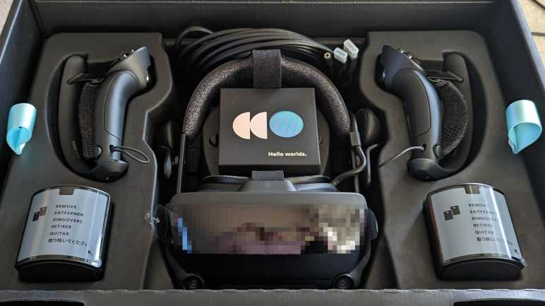
That was enough information for me to decide on buying one. One thing the manual couldn’t definitively show are the cables, so I had to wait until my system showed up to see them. They are laid out very tidily as expected of a customized power supply with all wires trimmed to necessary length. It is also free of all legacy power plugs. No floppy connector, no CD-ROM connector. Lack of clutter ensures great airflow through the airy middle section of the case.
I was happy to see robust provision for GPU power. There are a pair of 8-pin PCIe power plugs to feed the existing RTX 3080 card. Waiting in the wings just below them, tucked into a plastic bracket, are a duplicate set of extra PCIe power plugs. Together they are enough to feed a RTX 4090 card and I feel comfortable they are ready for whatever video card I might want to upgrade to in the future.
Only a single PCIe x1 slot is still open for future expansion, but historically that has been sufficient. This system came with 32GB of DDR5 RAM in two 16GB modules, leaving two additional memory slots open. There are two M.2 slots, one of which is occupied by a terabyte Samsung NVMe SSD and the other open. If I want to add some bulk HDD storage, there are two unoccupied 3.5″ drive bays. Both of which have SATA power plugs ready to go. However, only one of the two bays have a SATA data cable and the proprietary tool-less drive caddy installed. (Look for blue plastic in upper-right corner of picture.) SATA cables are easy to get and there are open SATA ports on the mainboard. It might not be as tidy since the length isn’t customized for the case, but I’m not worried about that. I’m considering buying one caddy now. It’s pretty cheap, and ensures the bay is usable even if Dell stops carrying this part. Or I could measure the dimensions of my existing caddy and 3D print a clone.
I saw no open 2.5″ drive bays, but that is a solvable problem. This system came with a laptop-sized DVD-R/W optical drive that I do not expect to ever use. However, that gives me the option to swap it out with a 2.5″ drive adapter. I’ll just have to remember to get the correct height adapter this time.
With the exception of power supply, I see standardized form factors for everything else I anticipate installing as either replacements or upgrades. The non-standardized elements have offset benefits like GPU support, tidy cabling, good airflow, etc. This compact integrated package seems well worth a ~15% premium over a DIY build. Now I have to see if it stands up to the test of time. I hope this machine will support many adventures (VR and otherwise) for years to come. Starting with revisiting my favorites to feel its upgraded power.
When I upgraded my VR headset to a Valve Index, I knew there’s a chance I’d want a new video card to go with it. The increased display resolution and refresh rate of the Index is significantly more demanding, possibly outpacing my existing RTX 2070 video card. Well, that expectation proved to be true. And to my small surprise, the challenge of running an Index has outpaced not only my video card but my processor as well! Faced with a major upgrade, I decided to get an entire system built around a RTX 3080. I combed through all of the Memorial Day 2023 sales I could find, and the winner of this competition was a Dell XPS 8950.
Most PCs built with a RTX 3080 video card cater to a market infatuated with multicolor LEDs. I don’t care to have them on my own computer, but I know how they work electronically and confident I can turn down the garish lights if they bother me. The bigger problem are functional tradeoffs made by cases optimized around those lights and related aesthetics accessories. For example, many of these PCs have clear sides to show off the hardware and lights inside. Glass and acrylic are poor thermal conductors and obviously obstructs airflow, not great for a power-hungry machine that needs to dissipate a lot of heat. Such are the silliness in HP Omen, Lenovo Legion, Dell Alienware, and other PCs competing in this market.
Dell’s Inspiron product line is their economy class for competing on price. If price was the biggest concern, I would buy parts and build a PC myself. I’m willing to pay a small premium to have a well-engineered system that I can expect to work well for several years. After that point I will contemplate piecemeal upgrades like a new video card. Between Dell’s low-priced Inspiron and their high-end Alienware is their XPS product line. Returning to the airline analogy: if Inspiron is economy class and Alienware is first class, XPS is their business class. I think I can find my Goldilocks “just right” point here. These products aren’t penny-pinched to last barely as long as the warranty. They should give all the performance I want with none of the gratuitous LEDs.
Dell’s list prices for XPS systems are roughly double what I would pay to buy similar components and assemble a system by myself, but I have never paid Dell MSRP and I don’t intend to start. The current Dell XPS desktop is the 8960 with 4000-series NVIDIA GPUs and 13-th generation Intel CPUs. This meant existing stock for older XPS 8950 with previous generation RTX 3080 video card and older generation CPU can sometimes be found with clearance pricing. Combined with Memorial Day and additional discounts, these not-bottom-basement machines can be had for less than 15% premium over self-assembly with bottom-basement components. This was good enough for a closer look.
I recently bought a Valve Index VR headset and it made great first impressions. A significant improvement over my older HP Windows Mixed Reality headset. Even though display resolution was only slightly higher than my old headset, it is now refreshing at 120Hz for smoother movement and a much more enjoyable experience. On the downside, my existing computer couldn’t keep up and I learned stutters at 120Hz are far more annoying (in the “discomfort leading to motion sickness” sense) than stutters at 90Hz or 60Hz.
When I bought my HP Windows Mixed Reality headset, it was paired with a laptop equipped with NVIDIA GTX 1060 mobile edition GPU. This barely met minimum system requirements for VR and I was no stranger to stutters even at 60Hz. A few years later, shortly after NVIDIA launched the RTX 2070 Super, there was a brief window of time when RTX 2070 (non-super) were discounted to a level I felt tolerable so I got one for VR duty. This was a big step above my laptop, but it could not keep up with a Valve Index.
Looking around the GPU market, NVIDIA recently launched their RTX 4070 which is reportedly on par with the RTX 3080. (Quick model number decoder: 3xxx vs 4xxx means earlier generation. xx8x vs. xx7x means higher tier product in that earlier generation.) Combined with easing of electronics component shortage and the cryptocurrency crash (about damned time), vendors clearing out older inventory dropped RTX 3080 market price drastically relative to insane heights of just a few months ago.
But if the new RTX 4070 is a newer GPU that is about as good for roughly the same money, why am I looking at the older RTX 3080? Because when I dug into RTX 4070 reviews and their associated comparison tests, I found that the RTX 3080 gets its benchmark scores from brute force pixel-pushing power while RTX 4070 gets them with help of features like DLSS. This is fine for most games, but such features add a bit of latency which is very bad for VR. As I’m looking at a GPU specifically for VR, the raw power of RTX 3080 is preferable to fancy smarts of RTX 4070.
I started looking around for a standalone RTX 3080 video card upgrade, then it occurred to me to look at Windows Task Manager to verify my GPU is indeed a bottleneck. The good news is that Task Manager confirmed my GPU utilization occasionally maxes out. The bad news is that I also noticed my 7th-gen Core i5 processor has its hands full. I was under the impression that games only care about single-core performance, but this information tells me newer VR titles are multicore aware and four cores won’t cut it anymore. I need to upgrade my CPU as well, which meant a new motherboard, which wants new DDR5 memory… at this point I might as well look at an entire new computer system.
Fortunately, the same pricing pressures on RTX 3080 video cards also lowered prices for complete systems prebuilt with a RTX 3080. Stacked with Memorial Day Sale discounts, I found several complete systems available at a reasonably small premium over what it would cost for me to buy parts from lowest-bidder retailers and build my own. Some of these are name brands who probably aren’t buying bargain-basement components from questionable Amazon/eBay/Newegg vendors as I would. Over Memorial Day weekend I evaluated all the deals I could find, and a Dell XPS 8950 looks very promising.
After five years with an HP Windows Mixed Reality VR headset, I looked over VR hardware choices in 2023 and decided to get a Valve Index. It has worked well through my first few sessions, and I wanted to write down my first impressions to see how they hold up after a few years. (In hindsight I wish I did this for my HP WMR headset when I got it in 2018.)
Reading various Valve Index reviews, the biggest recurring complaints focused on the display. The resolution is only incrementally higher than my five-year-old HP WMR headset. Compared against modern competition, it is lower than even the affordable Quest 2. Furthermore, it lacks the color and contrast of OLED panels used by some headsets in a similar price range. The redeeming feature of Index display is a high refresh rate of 120Hz with an experimental 144Hz mode available. While I know I would prefer OLED color and contrast, I don’t think it would be a huge immersion breaker in VR. The same with resolution: I’m sure I would appreciate a higher resolution display, but it hasn’t been a significant hinderance to my VR experience. What has been an actual problem were jerky movement. I decided I like Valve Index engineering team’s decision to prioritize high screen refresh rate, and indeed motion has been noticeably smoother. (For low complexity content, at least. More on that later.)
But 120Hz refresh rate might not have been the sole contribution. Some of that might be due to the tracking mechanism of a Valve Index. Rather than using visual tracking with a pair of cameras, the Valve Index required external base stations to serve as lighthouses helping my headset (and controllers) figure out where they are in space. This was a minor extra hassle during setup, but not so much to justify the complaints I’ve read about their setup. Theoretically this type of tracking would be a more responsive system because it requires less computation than camera-based visual positioning. I know VR motion is smoother, I just don’t know how much of that is 120Hz refresh rate, how much of that is beacon tracking, and how much is psychology.
A less-important but nevertheless appreciated bonus of beacon-based tracking is that my controller is no longer restricted to moving within a few camera cones of view. This came in useful for Half Life: Alyx which had two aspects problematic with the old headset. First is a motion where we put the controller over our shoulder to put stuff in our backpack, and the second is operating a mounted weapon late in the game. We have to aim with one hand on the rear of the large weapon, and fire with another hand on the handle midway up the left side of the weapon. In the real world this meant my left hand reached in front and the right hand near my chest. Problem: when looking up at the target, my HP WMR tracking camera couldn’t see my right hand near my chest! That made it very difficult to aim and a frustrating encounter on the old headset. With the Index controllers, it was a nonissue.
On that front, controller position tracking is improved but still not perfect. On the old headset, if I held my hand in front of my face and kept it steady, its position would jump around by roughly 5mm. I had hoped the new headset’s tracking system would fix this and keep it rock steady, but it did not. It still jumps around, though by a smaller amount. Maybe 2-3mm.
I really, really love Valve Index controllers, which were designed to allow me to open my hands without dropping them. Not merely for the VR immersion aspect, it also means less strain on my wrists because I don’t need to keep a death grip to keep them from flying across the room. Another improvement is moving the tracking detectors from a front ring to an outside arc. This reduced the frequency of (but did not eliminate) times I whack controllers against each other in enthusiastic play. Hopefully they’ll prove to be durable despite such abuse. I am worried about their shape, though. An advantage of rings is that, if I hit controllers against each other, the two rings would just bounce off each other.
In contrast, Index controller arcs have protrusions that can potentially snag on each other. It has yet to happen, so we’ll see if my worries are unfounded. And finally, these controllers have built-in batteries rechargeable via USB type-C. More convenient than constantly removing, recharging, and reinstalling NiMH AA batteries.
Back to the headset, I like having built-in speakers that hover a few centimeters away from my ears. I no longer have to either route audio to external speakers, which loses positional audio effects, or use earbuds I find uncomfortable. Even better are eye adjustments: both front-back (focal distance) and narrow-wide (IPD, interpupillary distance) are adjustable with the Index, I no longer have to put up with not-quite-right fixed positions. These features add weight relative to the HP WMR, but the Index also has an additional third top strap to better distribute that weight. Altogether these features (especially the eye adjustments) result in a more comfortable headset.
A damaged cable and lack of support motivated me to retire my previous VR headset. Valve enlisted iFixit for repair support and has provided repair parts. If I damage my Index cable, I could buy a replacement for $129 unless I want to use that excuse to buy a new headset again. I also damaged the face surround foam on my previous headset and bought aftermarket replacements. Official Index face gasket replacements are available at $40 for a two-pack, which I consider reasonable. They are magnetically attached which allows easy removal for cleaning. And when I removed my existing unit for a closer look, I found this cool little design detail:
There’s a tiny little ventilation slot molded into the top of this assembly. Airflow would be limited because of that lower tab blocking external light, but having this slot will help reduce the amount of humidity that gets built up inside a VR headset while in use. Small details like this show a great deal of thought went into design of this headset. I liked this headset enough to get a new PC worthy of it, and I hope they both hold up well to years of use in the future.
I broke my HP Windows Mixed Reality headset I bought five years ago in 2018. I made a repair effort, but the results are questionable with risk of electrical faults. I’m not comfortable risking damage to an expensive video card but I also appreciated having an excuse to upgrade.
A lot has changed in those five years. Most 3DOF VR garbage have faded away as the market realized that they sucked. Facebook poured a lot of money into virtual/augmented reality, including buying Oculus, spurring investment from others as well. Oculus launched the 3DOF Go headset (not interesting) followed by the 6DOF Quest headset (worth considering). Now we have the relatively affordable Quest 2 and the high-end Quest Pro. Both of which has onboard computing power to run standalone: no tether to break! But there are limitations to standalone operation: software-wise, we are limited to Oculus walled garden of applications, and graphics are limited by onboard hardware that are closer to phones than PCs. Fortunately Steam VR compatibility and better graphics fidelity can be had by using them as tethered PC VR headsets.
HTC, the other half of old PC VR duopoly, still exists and continues to evolve their line, releasing products across a price range that doesn’t dip as low as Quest 2 at the low end but definitely gets to Quest Pro on the high end. As far as I can tell, evolution has been incremental improvements without any significant innovation like Quest and their standalone operating ability.
Microsoft’s Windows Mixed Reality initiative seems to have lost momentum. After a flurry of headsets from multiple manufacturers five years ago, only Acer and HP released follow-up products. And it’s not just hardware releases that have dried up: I haven’t seen anything notable on the software front, either. Certainly nothing as notable as Oculus’ exclusives. I had really hoped Microsoft would port some variation of their Mars rover software from high-end Hololens to more affordable WMR headsets, but that never happened. It’s a good thing WMR headsets are compatible with Steam VR, because that’s where I’ve been spending my VR time.
I don’t think I’ve spent 1582 hours, though. That multiplies out to over two months. Searching online, I found many people complain Steam overcounts VR usage time. I’m going to blame that, because I really doubt I’ve spent two out of past sixty months of my life in VR. (Or if it is true, I don’t want to believe it.)
If I’m spending all my time in Steam VR anyway, then the obvious candidate is Valve Index who counts Steam VR as its home turf. It is a very well-reviewed headset with a notable innovation in handheld controller design. After evaluating the tradeoffs against other options on the market, I bought a Valve Index.