Luggable PC Motherboard Layout

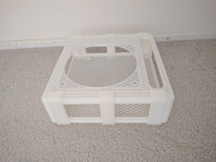
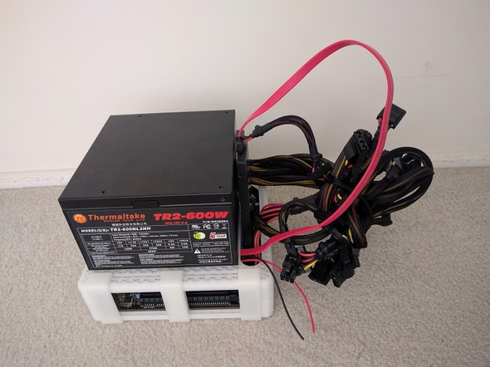
The previous post described how I decided to position the PSU (Power Supply Unit). Once the position was decided, the next task is to determine the motherboard position.

The first challenge is my desire to accept a full-sized ATX motherboard. Full-sized boards are the easiest to work on and has the best feature set. They also have highest sales volume, which usually mean less expensive. I knew my project would be easier with a smaller microATX or Mini-ITX motherboard, but I wanted to accept full-size.

However, accepting the full size board doesn’t necessarily mean I intend to use all the expansion slots. In fact, I am happy to block the majority of them, leaving just the primary PCI-Express slot available to the GPU.

selectcardsThe GPU itself is the next challenge. The primary slot is close to the CPU, which means it is going to stick up in the middle of the board, making the whole assembly awkward to fit. Again, I have an escape if I want it: there are PCIe extension ribbons available for purchase that allows more positioning flexibility for the GPU. They range from $89 well-regarded units from Digi-Key to $7 roll-of-the-dice units via mystery retailers on Amazon (*). I want to make this idea work without use of an extension, and avoid the variable that introduces to the system.

While researching the layout, I learned the primary slot is not in the same position across all motherboards, adding to the challenge. While most boards position them in the slot closest to the CPU (all of the Mini-ITX boards have to by necessity) some of the boards place it in the second position. And since high-powered GPUs are two slots wide, that means I need to allow for three expansion slots worth of space.

selectcomponentsThe GPU in the middle of the board leaves two rectangular volumes on either side: Both volume are candidates for use. One volume sits over the remaining expansion slots, and the other volume sits over the CPU.

The volume over the expansion slots are predictable. ATX spec restricts height of motherboard components in order to maintain clearance for expansion cards. If I’m OK with the absence of cards, that entire volume can be reclaimed.

In contrast, the volume over the CPU is less predictable. While the ATX spec allocated volume to CPU and accessories (most significantly, the CPU cooler) that volume is highly variable. Stock CPU coolers typically take much less volume than allocated, and many fancy CPU coolers exceed the volume.

Given those two choices, it was an easy choice to snug the PSU up against the motherboard in the volume allocated to expansion cards that won’t be there.

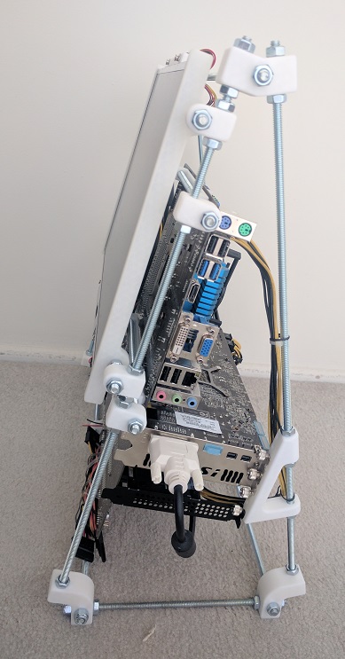
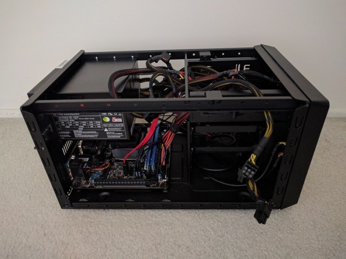
The last factor in positioning the motherboard is which direction I wanted the ports to be accessed. Pointing down is inconvenient to access. Pointing up makes ports vulnerable to damage from dropped items. So that leaves pointing left or right. Since the PSU power cable port is already on the right, I decided to face all the ports that way as well so everything the user needs to plug in is facing the same way.

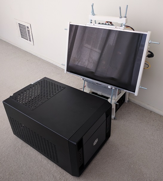
All of the above considerations resulted in the PSU+motherboard layout I used.

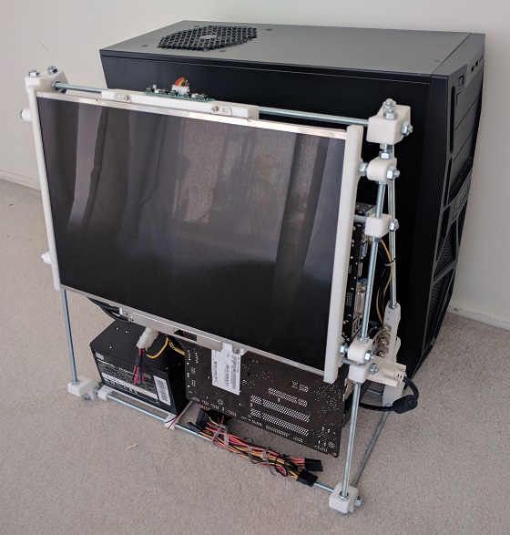
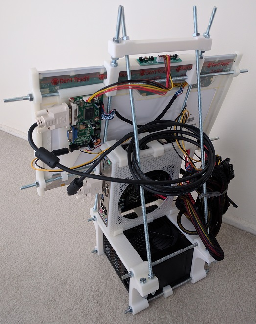
Next post: Positioning the screen.


(*) Disclosure: As an Amazon Associate I earn from qualifying purchases.

Luggable PC PSU Layout

To help optimize arrangement of Luggable PC components, I sketched them out in Fusion 360 so I can experiment with layout in CAD space. I was able to find the specification for the ATX motherboard and power supply, which allowed me to use official dimensions. Unfortunately I wasn’t able to do the same for the PCI-Express cards, because I needed to be a member of the PCI SIG to access the official specs. So I measured and guessed dimensions from the specific implementation I have on hand.

Power Supply Unit (PSU)

As the heaviest single component, I wanted the PSU at the bottom so the overall system is not top-heavy. The question is then: which way to orient the PSU? There were two considerations:

  1. PSU cooling intake: The standard ATX case layout places the PSU at the top of the case, drawing air from beneath. I can’t do that with the PSU at the bottom since a downward-facing intake would be blocked by the table surface. I tried the upward-facing intake once, in the Mini-ITX “Easel Frame 2.0” design. That turned out to be a bad idea because every time I dropped something (usually a screw) it would fall inside the PSU and I have to retrieve it to avoid short-circuiting the internals.
  2. PSU wiring: One side of the PSU takes the standard IEC AC cable. The opposite side is where all the DC wires go to the rest of the components. The decision is then whether to point them front-back or left-right. I didn’t want either of them to point towards the user, so I went with a left-right orientation for the wiring.

Taking care of those two considerations leave two good orientation for the PSU. One with the cooling intake facing front towards the user, or facing away from the user. In the current design, facing backwards allows an unobstructed air path so that’s the preferred position today.

Next post: Positioning the motherboard.

back


Luggable PC Gets Fancy Screen

closelidThe latest iteration of the home built luggable computer gets a fancy rotating screen to protect the screen while in transit and hold the screen up while in use.

The time pressure of making it ready for show-and-tell at the February Hackaday LA meet meant I hadn’t been documenting my lessons learned here.

Which is a shame, because there were quite a few 3D printing lessons learned while building this thing. I briefly mentioned a few of them on the project log update up on Hackaday.io but I intend to find the time to expand on those ideas as future posts on this blog. I just hope I can get them all written down before I forget.

Homebuilt Computer now “Luggable PC” on Hackaday.io

hackadayioprojectI’ve known about Hackaday for a while, both the professionally curated site hackaday.com and the public participation site hackaday.io. Some of the people behind the site are nearby which allowed me to easily attend some of their local events.

Most of the project pages I browsed through dealt with Arduino boards, Raspberry Pi boards, or even lower-level hardware. I wasn’t sure if a home built PC is the right kind of topic for the site until I brought my current prototype to one of these local meets. The staffers present assured me that it’d be a great project to document on hackaday.io.

All right then! I’ve created a project page to document my work so far, and I’ll continue documenting future iterations over there instead of here.

One of the Hackaday staffers took an interest in the project, wrote up a short blurb and posted it on the curated hackaday.com. I am very flattered by the attention and it was a great opportunity to see how other Hackaday users viewed the project.

The best comments are from people who appreciate the project and had constructive ideas and suggestions – this is what the site promised for project builders and I’m happy to see it working as intended.

There were a few variants of “This isn’t what I want. I want to see…” and while they are good project ideas, they’re not what I’m trying to accomplish here. Maybe they’ll feel inspired by my project to bring their own ideas to life!

And finally, the comments that dismissed the project. Pointing out shortcomings (some fair, some not) as criticisms without offering anything constructive to address the alleged issues. I just shrug off such criticism and focus on my work.

Positive or negative, the overall quality of the comments are far more articulate and intelligent than your average comment on YouTube.

I call that a win for Hackaday.

Homebuilt ATX All-In-One Computer

Scaling upwards from the previous project, I’m moved up from the Mini-ITX board to a (nearly) full sized ATX motherboard. The larger motherboard required a few more fastener locations but was not a significant challenge. The new challenge in this version was the addition of the GPU and properly securing it to the case.

back

Given the triangular profile of the frame, it took a little effort to design the triangular frame to fasten the GPU metal bracket against. At least, as compared to the normal rectangular computer cases. Thankfully CAD software like Onshape have no fear of trigonometry calculations.

side

It all works together but I’ve lost most of the size advantage over the standard mid-tower case. Here it is standing in front of the case that used to contain these components.

sizecompare

While the overall volume is still smaller than the generic PC case, it isn’t smaller by a whole lot. Yes, I do incorporate a screen while the standard case does not, but like the standard case I have a lot of unused empty space in my volume. Even though this made cable management easier and neater, a lot of waste is left over.

I decided the previous Mini-ITX version was on the “too small” side, and we’ve overshot into “too large”. The next iteration of this experiment will try to shrink the design and work towards “just right”


The small 3D printed brackets seen on this page were designed in the OnShape project “Easel PC“, which is available as an OnShape Public Document.

Homebuilt All-In-One Mini-ITX Computer

The previous experiment 3D printed just an enclosure for the Mini-ITX motherboard itself, it didn’t have much of a computer around. This project expands on the idea by building something to hold the rest of the computer components.

The physical size is larger than the build volume of the 3D printer so additional hardware were brought into the equation. Emulating the design for some early RepRap 3D printers, I started using commodity hardware store threaded rods as building structure.

The power supply unit is the heaviest single element and employed to provide the stable base. The new addition to the project is the screen built out of the LCD panel salvaged from an old broken laptop. I used a controller board that translated standard VGA/DVI signal to the panel’s proprietary signal to connect the panel to the rest of this system. Such controller boards can be purchased from one of several vendors on eBay.

The cable management is better than the previous effort, which admittedly set a low bar. The PSU is nice and heavy providing a stable base. Compared to the commodity Mini-ITX case: the overall package takes less desktop space (especially considering the screen) and overall roughly the same volume of space.

easel-back
A better-managed but still a tangle mass of cables.
easel-front
3D printed all-in-one “Easel PC” with a commodity Mini-ITX case.

This is a perfectly usable (if not very neat or pretty) PC. If this were the final goal, I would take a Dremel cutting wheel to cut off the extraneous ends on the threaded rods. Since I have no real need for a Mini-ITX AIO PC at the moment, though, I’m taking the lessons learned and recycling the metal bits for the next project.

Enclosure for Mini-ITX board

Customized computer cases are an interesting area to explore for 3D printing. The home-built desktop PC market is blessed with the luxury of choice, with a wide selection of components a builder can choose from. As a result of this, most desktop PC cases are wide-open designs capable of taking most combinations of components. This directly proves the old adage: “Jack of all trades, master of none.” In contrast, someone with a home 3D printer can custom design for a specific need built around specific components on hand. The result would be a master of one.

Before I can embark on some grandiose vision, I started with a small project built around the MSI AM1I motherboard. It is an inexpensive and highly integrated PC motherboard on the Mini-ITX standard. It had been installed in a Mini-ITX case that, though smaller than most desktop PC cases, still had a lot of wasted volume present to accommodate for components that I never installed.

fullcase
Mini-ITX computer with a great deal of wasted volume.

The Mini-ITX standard restricted the motherboard size to 17cm squared, which is convenient because my 3D printer can print up to 20cm squared. This meant I could print something encompassing the ITX dimension in one piece. I pushed for full minimalism resulting in this design available as OnShape public document “Mini-ITX enclosure“.

emptycase
3D printed Mini-ITX enclosure.

It has screw holes for only the mainboard and the power supply. The large hole on top is tailored for the specific power supply I had on hand, positioning its fan immediately above the motherboard. This allowed removal of the noisy CPU fan as the large power supply fan can pull double duty cooling the whole works resulting in a small neat compact setup.

When I assembled the parts, though, things didn’t look as neat as I imagined:

minimalist
My, what a tangled nest you have.

I had underestimated the chaotic bundle of wires coming out of the power supply. Most of the wires were completely unnecessary and could be cut if this were the final product, but I didn’t want to do that just for an experiment. The remaining wires could be shortened for such a compact layout, but again I didn’t want to break out the wire clipper and soldering iron for sake of the experiment.

The other item I didn’t account for was the storage device, in this case an old SSD in 2.5″ form factor, awkwardly wedged into a slot. (See the red SATA cable in the picture.) I justified this oversight by the fact that most modern ITX boards have on-board M.2 SSD slots, making a separate mounting bracket unnecessary. Truthfully, though, I forgot.

I had fun building this proof-of-concept with old expendable components in case something went wrong. Next custom PC project will be bigger, with more powerful components, and hopefully the wires will be better managed as well!

Let the App… Materialize!

materializecsslogo
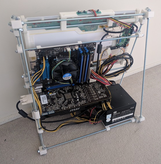
After I got the Google sign-in working well enough for my Rails practice web app, the first order of business was to build the basic skeleton. This was a great practice exercise to take the pieces I learned in the Ruby on Rails Tutorial sample app and build something of my own design.

The initial pass implemented basic functionality but it didn’t look very appealing. I had focused on the Rails server-side code and left the client-side code simple plain HTML that would have been state-of-the-art in… maybe 1992?

Let’s make it look like something that belongs in 2017.

The Rails tutorial sample app used Bootstrap to improve the appearance and functionality of the client-side interface. I decided to take this opportunity to learn something new instead of doing the same thing. Since I’m using Google Sign-In in this app, I decided to adopt Google’s design concepts to my client-side appearance as well.

Web being the web, I knew I wouldn’t have to start from scratch. I knew about Google’s own Material Lite and thought that would be a good candidate before I learned it had been retired in favor of its successor, Material Components for the web. One of the touted advantages was improved integration with different web platforms. Sadly Rails was not among the platforms with examples ready-to-go.

I looked around for an existing project to help Rails projects adapt Google’s design language, and that’s when I found Materialize: A library that shares many usage patterns with Bootstrap. The style sheets are even written using SASS, native to default Rails apps, making for easy integration. Somebody has done that work and published it as Ruby gem materialize-sass, so all I had to do was add a single line to use Materialize in my app.

Of course I still had to put in the effort to revise all the view files in my web app to pick up Materialize styling and features. That took a few days, and the reward for this effort is a practice web app which no longer look so amateurish.

The Cost for Security

In the seemingly never-ending bad news of security breaches, a recurring theme is “they knew how to prevent this, but they didn’t.” Usually in the form of editorializing condemning people as penny-pinching misers caring more about their operating cost than the customer.

The accusations may or may not be true, it’s hard to tell without the other side of the story. What’s unarguably true is that security has some cost. Performing encryption obviously takes more work than not doing any! But how expensive is that cost? Reports range wildly anywhere from less than 5% to over 50%, and it likely depends on the specific situations involved as well.

I really had no idea of the cost until I stumbled across the topic in the course of my own Rails self-education project.

I had designed my Rails project with an eye towards security. The Google ID login token is validated against Google certificates, and the resulting ID is salted and hashed for storage. The code for this added security were deceptively minor, as they triggered huge amounts of work behind the scenes!

I started on this investigation because I noticed my Rails test suite ran quite slowly. Running the test suite for the Rails Tutorial sample app, the test framework ran through ~120 assertions per second. My own project test suite ran at a snail’s pace of ~12 assertions/second, 10% of the speed. What’s slowing things down so much? A few hours of experimentation and investigation pointed the finger at the encryption measures.

Obviously security is good for the production environment and should not be altered. However, for the purposes of development & test, I could weaken them because there would be no actual user data to protect. After I made a change to bypass some code and reducing complexity in others, my test suite speed rose to the expected >100 assertions/sec.

Granted, this is only an amateur at work and I’m probably making other mistakes doing security inefficiently. But as a lesson to experience “Security Has A Cost” firsthand it is eye-opening to find a 1000% performance penalty.

For a small practice exercise app like mine, where I only expect a handful of users, this is not a problem. But for a high-traffic site, having to pay ten times the cost would be the difference between making or breaking a business.

While I still don’t agree with the decisions that lead up to security breaches, at least now I have a better idea of the other side of the story.

Protecting User Identity

google-sign-inRecently, web site security breaches have been a frequent topic of mainstream news. The technology is evolving but this chapter of technology has quite some ways to go yet. Learning web frameworks gives me an opportunity to understand the mechanics from web site developer’s perspective.

For my project I decided to use Google Identity platform and let Google engineers take care of identification and authentication. By configuring the Google service to retrieve only basic information, my site never sees the vast majority of personally identifiable information. It never sees the password, name, e-mail address, etc.

All my site ever receives is a string, the Google ID. My site uses it to identify an user account. With the security adage of “what I don’t know, I can’t spill” I thought this was a pretty good setup: The only thing I know is the Google ID, I can’t spill anything else.

Which led to the next question: what’s the worst that can happen with the ID?

I had thought the ID is something Google generated for my web site. More specifically my site’s Client ID. I no longer believe so. A little experimentation (aided by a change in Client ID for the security issue previously documented) led me to now believe it’s possible the Google ID is global across all Google services.

This means if a hacker manages to get a copy of my site’s database of Google ID, they can cross-reference to databases of other compromised web sites. Potentially assembling a larger picture out of small pieces of info.

While I can’t stop using Google ID (I have to have something to identify an user) I can make it more difficult for a hacker to cross-reference my database. I’ve just committed a change to hash the ID before it is stored in the database. Salted with a value that is unique per deployed instance of the app.

Now for a hacker to penetrate the identity of my user, they must do all of the following:

  1. Obtain a copy of the database.
  2. Obtain the hashing salt used by the specific instance of the app which generated that database.
  3. Already have the user’s Google ID, since they won’t get the original ID out of my database of hashed values.

None of which are impossible, but certainly a lot more effort than it would have otherwise taken.

I think this is a worthwhile addition.

Limiting Google Client ID Exposure

google-sign-inToday’s educational topic: the varying levels of secrecy around cloud API access.

In the previous experiment with AWS, things were relatively straightforward: The bucket name is going to be public, all the access information are secret, and none of them are ever exposed to the user. Nor are they checked into the source code. They are set directly on the Heroku server as environment variables.

Implementing a web site using Google Identity got into a murky in-between for the piece of information known as the client ID. Due to how the OAuth system is designed, the client ID has to be sent to the user’s web browser. Google’s primary example exposed it as a HTML <meta> tag.

The fact the client ID is publicly visible led me to believe the client ID is not something I needed to protect, so I had merrily hard-coded it into my source and checked it into Github.

Oops! According to this section of the Google Developer Terms of Service document, that was bad. See the sections I highlighted in bold:

Developer credentials (such as passwords, keys, and client IDs) are intended to be used by you and identify your API Client. You will keep your credentials confidential and make reasonable efforts to prevent and discourage other API Clients from using your credentials. Developer credentials may not be embedded in open source projects.

Looks like we have a “secret but not secret” level going on: while the system architecture requires that the client ID be visible to an user logging on to my site, as a developer I am still expected to keep it secret from anybody just browsing code online.

How bad was this mistake? As far as security goofs go, this was thankfully benign. On the Google developer console, the client ID is restricted to a specific set of URIs. Another web site trying to use the same client ID will get an error:

google-uri-mismatch

IP addresses can be spoofed, of course, but this mitigation makes abuse more difficult.

After this very instructional detour, I updated my project’s server-side and client-side code to retrieve the client ID from an environment variable. The app will still end up sending the client ID in clear text to the user’s web browser, but at least it isn’t in plain sight searchable on Github.

And to close everything out, I also went into the Google developer console to revoke the exposed client ID, so it can no longer be used by anybody.

Lesson learned, moving on…

Adventures in Server-Side Authentication

google-sign-inThe latest chapter comes courtesy of the Google Identity Platform. For my next Rails app project, I decided to venture away from the user password authentication engine outlined in the Hartl Ruby on Rails Tutorial sample app. I had seen the “Sign in with Google” button on several web sites (like Codecademy) and decided to see it from the other side: Users for my next Rails project will sign in with Google!

The client-side code was straightforward following directions in the Google documentation. The HTML is literally copy-and-paste, the JavaScript needed some reworking to translate into CoffeeScript for the standard Rails asset pipeline but wasn’t terribly hard.

The server side was less straightforward.

I started with the guide Authenticate with a Backend Server which had links to the Google API Client Library for (almost all) of the server side technologies including Ruby. The guide page itself included examples on using the client library to validate the ID token in Java, Node.JS, PHP, and Python. The lack of Ruby example would prove problematic because each flavor of the client library seems to have different conventions and use different names for the functionality.

Java library has a dedicated GoogleIdTokenVerifier class for the purpose. Node.JS library has a GoogleAuth.OAuth2 class with a verifyIdToken method. PHP has a Google_Client class with a verifyIdToken method. And to round out the set, Python library has oauth2client.verify_id_token.

Different, but they’re all in a similar vein of “verify”, “id”, and “token” so I searched the Ruby Google API client library documentation for those keywords in the name. After a few fruitless hours I concluded what I wanted wasn’t there.

Where to next? I went to the library’s Github page for clues. I had to wade through a lot of material irrelevant to the immediate task because the large library covers the entire surface of Google services.

I thought I had hit the jackpot when I found reference to the Google Auth Library for Ruby. It’s intended to handle all authentication work for the big client library, with the target completion date of Q2 2015. (Hmm…) Surely it would be here!

It was not.

After too many wrong turns, I looked at Signet in detail. It has a OAuth2::Client class, which sounded very similar to the other libraries, but it had no “verify” method so every time I see a reference to Signet I keep deciding to look elsewhere. Once I decided to read into the details of Signet::OAuth2::Client, I finally figured out that it had a decoded_id_token method that can optionally verify the token.

So it had the verification feature but the keyword “verify” itself wasn’t in the name, throwing off my search multiple times.

Gah.

Nothing to do now but to take some deep breaths, clear out the pent-up frustration, and keep on working…