FreeCAD Notes: Mirror

FreeCAD offers multiple ways to constrain a distance: strictly along vertical axis, strictly horizontal, or the shortest distance between those two points. This is more direct than Onshape’s way of heuristically guessing user intent, and I can see myself learning to like it. What I will miss, though, is Onshape’s sketch mirroring mechanism that can mirror along arbitrary lines and maintain relationship with the original. FreeCAD 0.20.2 doesn’t seem to do either.

Many of my mechanical designs have symmetric features. Just as one example, a commodity micro servo is mounted via two tabs, each held with a small screw. The mounting tab and screw hole is symmetric about the center. I prefer not to duplicate effort by drawing two tabs and two screw holes. In Onshape, i can draw just one side and a line on my sketch representing the center. I can then use the mirror function to generate the other side. If I need to refine my sketch later, I can fine tune dimensions on the side I drew and Onshape will automatically update the mirrored side to reflect my changes.

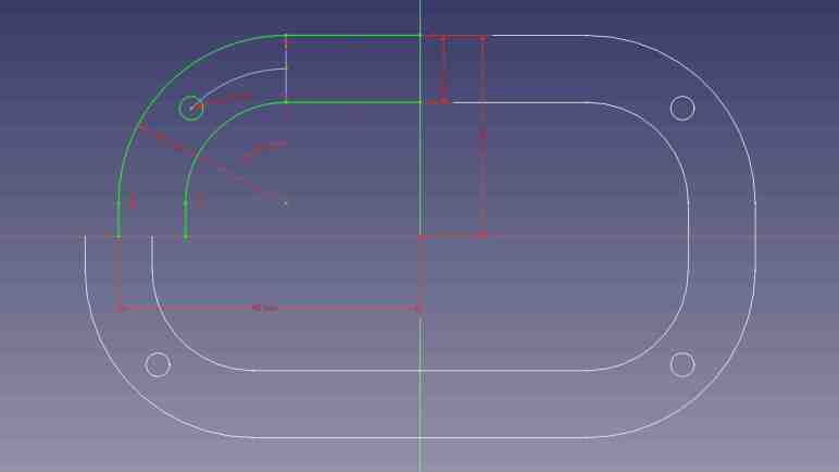
FreeCAD’s Sketcher workbench does have a “Mirror Sketch” feature, but it does not mirror about arbitrary lines in the sketch. It can only mirror about the X axis, the Y axis, or the Origin point which mirrors both X and Y. Here I’ve sketched out one quarter of a symmetric part (Displayed jn green) and mirrored it three times (about X, about Y, and about Origin. Displayed in white.) to create the entire perimeter of this test.

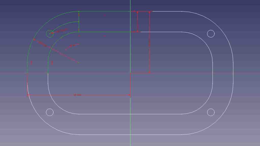
Furthermore, I didn’t get to select which feature to mirror. “Mirror Sketch” mirrors everything in the sketch and placed results in a new sketch, which seems to sever all association with the original sketch.

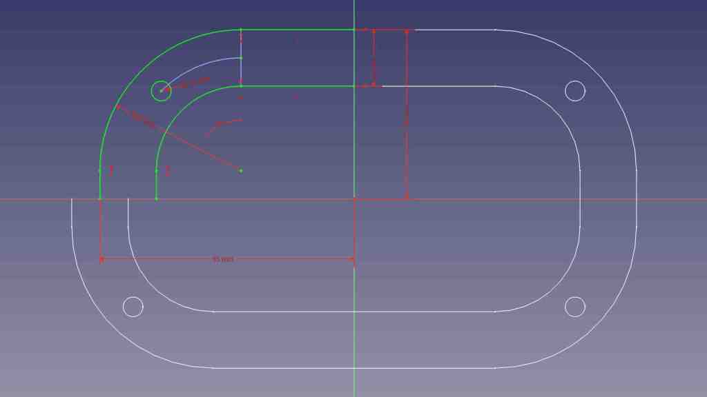
If I change a dimension in the original sketch, in this experiment the width, none of the mirrors were updated to reflect my change. There’s a “Merge sketches” feature to put everything back into the same sketch, but that doesn’t fix this problem.

There’s a good chance I can accomplish what I want with a different FreeCAD feature, much as how I wanted “Midpoint” and eventually found a solution via “Constrain symmetrical”. But as of this writing I haven’t found my desired functionality. Until I do, sketching symmetric features in FreeCAD will require duplicate effort sketching features that I could mirror in Onshape. I will then have to manually link duplicated features with “Constrain equal” so any future updates to critical dimensions will be properly propagated through symmetric features. This will not be a major dealbreaker against using FreeCAD, just mildly annoyed at the extra effort taking more time.

FreeCAD Notes: Distance

I’m on my FreeCAD learning journey and I’ve had to change some of my Onshape habits. For sketching, I was able to adapt from Onshape’s “Midpoint” constraint to FreeCAD’s “Constrain Symmetrical” once I figured out a workaround to avoid redundancy errors with FreeCAD’s implicit constraints.

I’m generally in favor of having one way to do something instead of offering multiple similar ways, so I’d be OK if it was a deliberate decision not to add a dedicated “Midpoint” constraint when “Constrain Symmetrical” is functionally equivalent. But I doubt it, because that’s not been the typical FreeCAD pattern. It already has two confusingly similar workbenches “Part” and “Part Design“, and multiple competing workbenches for assemblies. (It’s up to “Assembly3” and “Assembly4” now.) And right on the sketching constraints toolbar, where a “Midpoint” may have been deemed redundant, we have three separate tools to denote linear dimension: “Constrain horizontal distance”, “Constrain vertical distance”, and “Constrain distance.”

Each of these have valid use, because these distance constraints are driven by project requirements that may dictate we measure horizontally, measure vertically, or measure the direct line distance. Once I saw these three options listed side by side I immediately understood why they were there, but I was surprised because Onshape handled the problem differently.

In Onshape, there’s just a single dimension operation. In my experience it is usually a direct line measurement equivalent to FreeCAD’s “Constrain distance”. But sometimes I do need to constrain distance along a horizontal or vertical axis. In these cases, Onshape lets me drag the distance number away from the object. If I drag far enough away horizontally, it becomes a vertical distance constraint. The number is recalculated accordingly, and I can edit it afterwards as desired. A horizontal distance constraint is done similarly, by dragging the number away from the object either above or below vertically. This heuristic typically works well, but can be frustrating for features at a shallow angle: I would have to drag pretty far before Onshape understood I don’t want the shallow angle, I want horizontal/vertical.

With that experience in mind, I think I might come to prefer having three distinct and explicit methods to constrain a distance despite my typical preference to have a single way to do something. The only downsides with this approach are a bit of extra screen real estate taken up by the toolbar, and the fact I’ll eventually have to memorize three different keyboard shortcuts to become fluent at FreeCAD.

FreeCAD Notes: Midpoint

In between musing about VR projects and other random ideas, I’ve been returning to FreeCAD and learning my way bit by bit. After my initial introduction to Part Design workbench I’ve been gradually gaining proficiency with it. Learning FreeCAD required changing some patterns I’ve developed while working in Onshape. Such changes were expected for adopting a different software package, so this is not a surprise, but adjustment takes time. The first “that took longer than it should” switchover example was replacing Onshape’s midpoint constraint.

When sketching my design in Onshape, I frequently use the midpoint constraint to keep something in between two other things. Most commonly, I would place a point on a construction line and then select the midpoint constraint. FreeCAD doesn’t have a dedicated “Midpoint” constraint but, for putting a point in the midpoint of a line, I should be able to use the “Symmetrical” constraint to accomplish the same thing. But as soon as I impose the “Symmetrical” constraint on my point and line, everything turns orange indicating some kind of an error. I pressed “Undo” so I could figure out a different way that wouldn’t cause an error. But no matter what I tried, things would turn orange.

After several attempts all ending in orange lines, I thought “Self, go understand the error message!” It took me a minute to figure out where the error was shown in FreeCAD’s interface, but once I did, I saw the error was “Redundant constraints: (61)” This was confusing to me because the point I had placed on the line was definitely not the midpoint, so the “Symmetrical” constraint was definitely required. What was the redundant constraint? FreeCAD’s list of problematic constraint was a single number 61, which told me nothing. Fortunately, the (61) was a link I could click to take me to a “Constrain point onto object” linking the point and line.

How did this happen? When I clicked to place a point on the line, FreeCAD tried to be helpful and automatically added a “Constrain point onto object” between the two. Not knowing this had happened, I blissfully proceeded to add “Constrain symmetrical”. Doing so made “Constrain point onto object” redundant because a line’s midpoint is by definition always on that line.

In other words: FreeCAD implicitly added a constraint and, when I made my wish explicit, complained that my explicit specification collided with its implicit inference. That was annoying, I had nothing to do with that implicit constraint but now I have to deal with it. Or do I? Looking at FreeCAD’s user interface immediately below where “Redundant constraints (61)” was shown, I saw a checkbox for “Auto remove redundants”. Hey, that sounded promising!

Except it was not useful. I checked that option and tried again. When I clicked to add a point on the line, it still added “Constrain point onto object” as before. Then when I added “Constrain symmetrical”, FreeCAD looked at the two conflicting constraints and automatically removed the more recent one: “Constrain symmetrical”. Which is to say, FreeCAD deleted my explicit wish in favor of its own incorrect guess. Bah.

Once I understood what happened, I could devise a workaround. When adding the point, I have to be careful to click in the empty space near the line but not on the line. Doing this meant FreeCAD would not add “Constrain point onto object” so when I explicitly specify “Constrain symmetrical” afterwards there would be no redundancy to cause problems. This would be a minor change in my behavior, and I think I’ll get the hang of it quickly like FreeCAD’s distance constraint feature.

FreeCAD Notes: Part Design First Impressions

Watching MangoJelly’s FreeCAD tutorials on YouTube, I learned the power of FreeCAD workbenches and how FreeCAD supports different workflows via different combinations of workbenches. While I can follow along with what’s on screen, that’s different from my own personal workflow that I’ve been using with Fusion 360 and Onshape. And it’s not yet clear if FreeCAD can do the same or if I have to change my personal workflow to fit FreeCAD.

The tutorial’s first example uses the Part Design workbench. It is focused on creating a single part and only a single part: any operations that result in multiple pieces (like cutting a shape in half with boolean operation) will be flagged as an error. It is also focused on keeping individual operations simple and process them sequentially. We create a simple shape then modify that shape with additional operations until we reach the shape we want.

I understand this behavior resembles Tinkercad and is intended to be a more beginner-friendly way to reason about object modeling. But I saw two problems pretty immediately in my brief playtime: first, by building up a long chain of operations, modifying any single step will have repercussions on every step that follows. This workflow aimed a loaded gun at the beginner’s feet, just waiting for the dreaded TNP to pull the trigger. Second, by encouraging individually simple steps, it also encourages scattering part feature dimensions across all of those steps. The size of the overall part might be in the first step, but to find the size of a hole cut in that part we have to dig into the chain of operations to find the cutting operation.

These two observations meant Part Design workbench didn’t make a great first impression on me. I prefer to create few sketches up front with almost all of the information. (Ideally just three: top view, side view, front view.) And then build my parts from dimensions in those few sketches. If I change those dimensions afterwards, I expect to have the parts recalculated automatically.

I didn’t see anything that resembled my preferred workflow until part 12, when MangoJelly goes into “Master Sketch”. The tutorial shows how to use master sketch with Part Design workbench, which should mitigate my concerns with the default workflow.

Putting it into practice, though, is going to take more practice. Trying to use my master sketch in Part Design is continually frustrated by some kind of misunderstanding I have with how references work in FreeCAD. At one point I got frustrated enough to ask: “I wonder if this is easy in Part workbench” and tried to extrude my sketch there.

My fumbles in Part workbench created multiple surfaces instead of a solid shape with four holes, reminding me of another beginner-friendly feature of Part Design: it hides all the surface-related features, keeping things focused on solid 3D shapes. This is good, but I have a lot to learn before I can make Part Design workbench do my bidding.

FreeCAD Notes: Workbenches

After deciding I’ve had enough of a distraction from learning FreeCAD, I started watching a YouTube tutorial playlist by MangoJelly. Watching someone else use FreeCAD is instructive because it is a difficult piece of software to use without some guidance. When I dove to play on my own, I got far enough to create a new FreeCAD document then figuring out I need to launch a workbench. But a default FreeCAD installation has over twenty workbenches to choose from, and no guidance on where to start or even what a workbench is.

After about 4-5 videos into the MangoJelly playlist, I learned a workbench in FreeCAD is a mini CAD package inside FreeCAD designed for a particular task. A workbench generate data for the underlying FreeCAD infrastructure that could be consumed by another workbench, or be useful directly. To use an imperfect analogy: if Microsoft Office were FreeCAD, its workbenches would be Word, Excel, PowerPoint, Outlook, etc. Except unlike Office, we can install additional FreeCAD workbenches in addition to the default list and we can even write our own.

Workbenches make sense as a software architectural approach for a large open-source project like FreeCAD. People with interesting CAD ideas can prototype them as a FreeCAD workbench without writing a CAD system from scratch. As a demonstration of the power of workbenches, I was impressed by the fact entire code-cad packages can interface with FreeCAD in the form of a workbench.

  • There is an OpenSCAD workbench which bridges FreeCAD with OpenSCAD (which must be installed separately) to consume OpenSCAD script and converts the result into an OCCT mesh that can be used by other FreeCAD workbenches.
  • There is also a CadQuery 2 workbench that can be used in a similar way. With the advantage that since CadQuery is also built on OCCT, in theory its output data can be used by other FreeCAD workbenches more easily as OCCT primitives instead of converting into a mesh.

Such flexibility makes FreeCAD workbenches a very powerful mechanism to interoperate across different CAD-related domains. On the downside, such flexibility also means the workbench ecosystem can be confusing.

  • MangoJelly started the tutorial by using the “Part Design” workbench, and a few episodes later we are shown the “Part” workbench. Both build 3D geometries from 2D sketches and have similar operations like extrude and revolve. MangoJelly struggled to explain when to use one versus the other, leaving me confused. I wonder if FreeCAD would ever choose one and discard the other or would it just continue down the path of having two largely overlapping workbenches.
  • A cleaner situation exists with the “Raytracing” workbench which has not been maintained for some time. There now exists a “Render” workbench with most of the same features. Thus, the unmaintained “Raytracing” will no longer be a part of default FreeCAD installation after 0.20. This is perhaps the best-case scenario of FreeCAD workbench evolution.
  • But “Part” vs. “Part Design” is not the only competition between similar FreeCAD workbenches. There’s no single recommended way to build multipart assemblies, something I would want to do with a Sawppy rover. As of this writing the FreeCAD wiki describes three viable approaches each represented by a workbench: “A2plus”, “Assembly3” and “Assembly4”. I guess evolution is still ongoing with no clear victor.

Learning about workbenches gave me a potential future project idea: If I build a future version of Sawppy rover in FreeCAD, would it make sense to also create an optional Sawppy workbench? That might be the best way to let rover builders change Sawppy-specific settings (heat-set insert diameter) without making them wade through the entire CAD file.

That’s an idea to investigate later. In the meantime, I should at least learn how to work with the Part Design workbench that’s used a lot as in MangoJelly’s YouTube tutorials.

FreeCAD 0.21 is Coming Soon

I liked the potential promise of doing CAD via code instead of drawings, but current implementations left me unconvinced. Partly because today’s existing code-cad solutions are built on OpenSCAD (I’m not a fan) and partly because it is a huge change in mindset. I might find motivation to give it an honest effort in the future, but for the immediate future I’ll retreat back to FreeCAD and the sketch-based workflow I’ve been familiar with. Part of this decision came from getting a sense of FreeCAD’s direction in their “What’s going on at FreeCAD?” communications.

The biggest question I had is about the infamous topological naming problem. (TNP) This always comes up whenever people discuss switching from a commercial closed-source CAD package to open-source FreeCAD. Opinions range on a wide spectrum from the snobby “only dumb users run into TNP” to “widespread adoption would not be possible until TNP is mitigated” to dismissive “TNP exists because FreeCAD is not a serious project”.

I don’t personally have an opinion on FreeCAD TNP, since I haven’t used it very much yet. But I know enough to be aware it’s not exclusive to FreeCAD. Many other CAD packages have problems along those veins to varying degrees. For my Sawppy CAD file in Onshape, part geometry changes are sometimes followed by notifications of failed fillet operations. Or worse, fillet operations that don’t fail but went someplace unexpected.

But my opinion is not as important as the opinion of the people behind the project. Do they even consider TNP to be a problem that needs solving? Thanks to “What’s going on at FreeCAD?” I learned the answer is a definite YES. In fact, they consider it one of the (if not THE) top problems that need to be solved before they can declare FreeCAD version 1.0.

I don’t understand enough FreeCAD internals to understand how they intend to address TNP, but there IS a plan, and the project is at a critical stage. The underlying support infrastructure is in place, but starting to utilize that infrastructure across FreeCAD will likely degrade performance until everything is done. This will be the next public release. It won’t disrupt users who aren’t part of making the great TNP fix, while providing a stable foundation for people who are. Allowing them to implement and test TNP solutions. (And if things go seriously wrong, it leaves the option open to rip out that infrastructure and try a different approach without breaking future versions.) Since TNP is not fixed yet, the next release will not be 1.0. It’ll just be the next increment: 0.21.

I first started looking at FreeCAD shortly after 0.19 released and online resources (aimed at 0.18 and earlier) were in turmoil working to update. Today, 0.20 had been out for over a year and most resources have stabilized. I should take advantage of that and learn 0.20 as quickly as I can before 0.21 causes another round of disruptions.

So where should I start? There was a recent Hackaday post about FreeCAD, which elicited the usual cacophony of comments arguing about TNP. But in between the noise I noticed multiple recommendations for MangoJelly’s YouTube tutorial series. Video tutorial is not my preferred format, but if it’s a popular place to start, I’m willing to give it a shot.

Taking Another Look at FreeCAD

Creating Sawppy the Rover was a great learning experience, sharing it with the world was even more so. It wasn’t until I started receiving feedback that I learned tools for hardware projects lag behind the software world in their ability to support an open-source community. I published a wishlist earlier but haven’t made any progress on finding answers. But I know FreeCAD is going to come up in some way. FreeCAD is a large and high-profile open-source CAD project. It will either be part of the solution, or I will need to know it well enough to articulate why it isn’t.

Since I had always intended for Sawppy to be open-source, I looked into FreeCAD from the start. Back then, even people behind the project cautioned it was yet ready for prime time, so I took their advice and looked elsewhere. A few years later, FreeCAD release 0.19 close coincided with Autodesk starting to… shall we say… “aggressively increase revenue” from Fusion 360 users. This caused dissatisfaction within my maker circles. Some people took another look at FreeCAD and reported: “It’s not as bad as it used to be!”

That was hardly a ringing endorsement, but enough for me to take another brief look. My problem at the time was that 0.19 was hot off the press and all the available resources online were for 0.18 or earlier. And since FreeCAD 0.19 changed significantly, those resources were out of date. I made a mental note to come back later.

As of this writing in July 2023, the latest stable release of FreeCAD is 0.20 which was released June 2022. I expect a year’s time is enough for online resources to be aligned with 0.20 and thought I should give it another look. I started reading documentation and encountered a lot of unfamiliar terminology. This is normal whenever I venture into any new technical field, though it does slow down my reading a lot as I looked up definition for each.

I quickly got distracted by a specific acronym: OCC which stands for Open Cascade. (Also OCCT, for Open Cascade Technology.) It is the beating heart of 3D geometry math at the core of FreeCAD. Learning about OCCT opened my eyes to possibilities beyond FreeCAD.