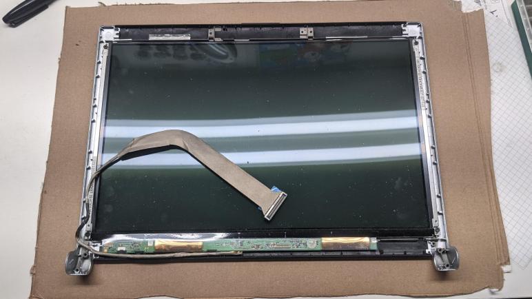
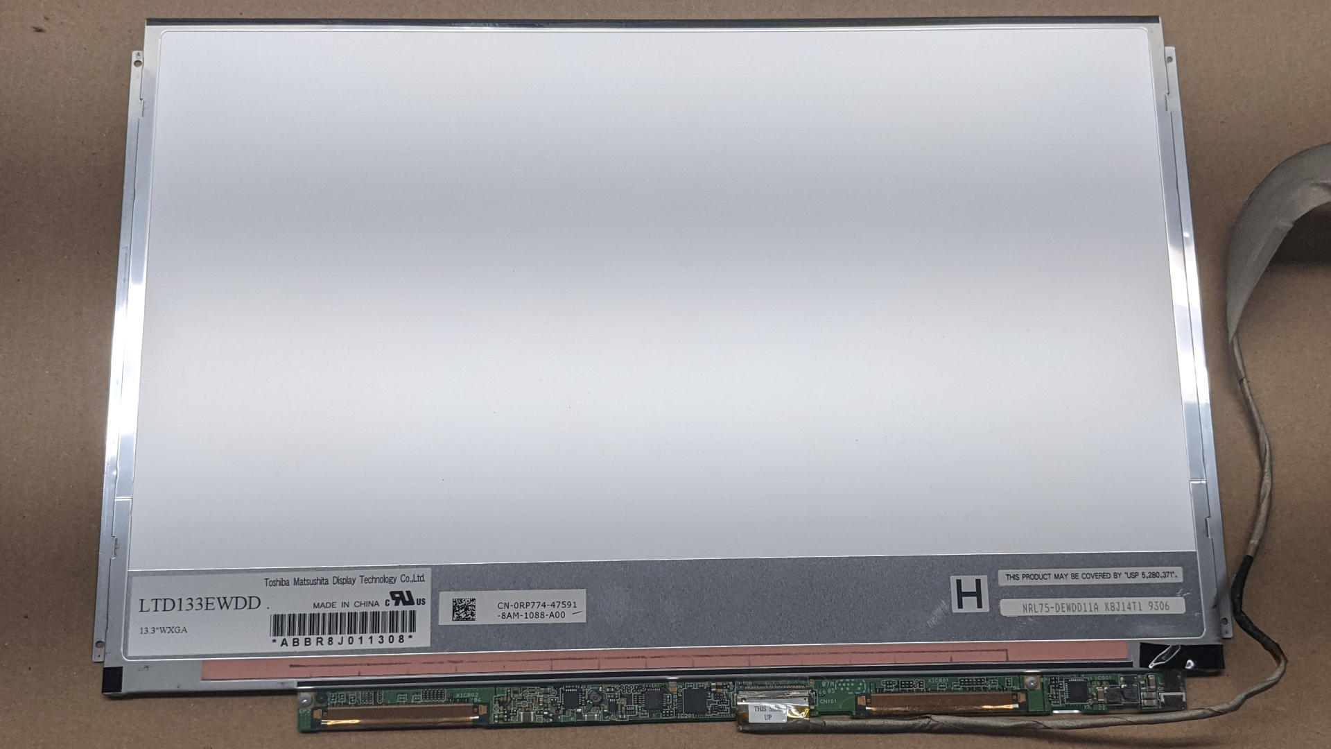
Examining the integrated control board on a Toshiba LTD133EWDD panel I had pulled out of a Dell XPS M1330 laptop, I found no information on communicating with its integrated LED driver chip so I’m going ahead with the backup plan of seeing if I could drive the LEDs directly. [NOTE: This was written before Randy commented with a link to the datasheet.] First order of business was to remove the LCD pixel array in front of the backlight. A marvel of miniaturization in its day, now I am no longer interested in its 1280×800 pixel resolution.

A thin strip of black tape around all four edges held the glass sheets in the frame. I admire how it precisely mated up against the edge of the polarizer film. It was either applied by a machine or hands of great skill.
Once the tape was removed, the glass LCD array was held only by the high density data connectors. Before I peeled them off, I noticed one item of interest: I see alignment marks that I don’t recall seeing on previous LCD arrays I had peeled off in this way.

While peeling off the high density pixel data connectors, I was reminded that glass is fragile and easily crack when abused.

Once the LCD pixel array was removed, I returned to examining the LED backlight connection. I see an eight-conductor connector, but only seven wires in the flexible cable. One of which is thicker than the rest. Based on the experience so far, my first guess are six LED strings in parallel sharing a common current supply but with six individual current sinks.

Flipping the circuit board over, I found several sets of six pads on the board. The circular pads look like they were designed for pogo pins on a test rig. The rectangular pads look like they are provisions for decoupling capacitors that were never installed. We could see the top row of six are all connected, consistent with a common supply. The bottom six each correspond to the six current sinks on the connector.
One interesting novelty was that while the leftmost four connectors are strictly in order, the fifth and six conductors were swapped. So if we count the small vias connecting to the connector on the other side in left-to-right order as 1,2,3,4,5,6. The rectangular pads are in the order of 1,2,3,4,6,5. Perhaps this was merely done to make PCB routing easier, but I’m curious if there’s a more profound reason.
Another interesting item of note is the surface mounted switch immediately to the right and below these pads. This switch would not have been user-accessible in the laptop. Even a servicing technician would have to peel off a plastic protective layer before this switch could be flipped. What does it do, and why is it important enough to take the hit of manufacturing parts cost and complexity? I can smell a story here but not enough interest to chase it down.
In my past LED backlight salvage operations, my next step would be to solder some wires to these points and determine the electrical properties of this string. But now I am armed with a dedicated LED backlight tester, and I could put it to work and probe these points directly. There are indeed six parallel strings of 10 LEDs per string. They each drop approximately 32V at 20mA. This is information I could have determined without the dedicated tester, but having the right tool made the job quick and easy.

Once I had these backlight details identified, I could store it away for future project. But it also had some auxiliary items I should take care of first, like a nice metal frame.