Powering Up Toyota Audio Head Unit (86120-08010)

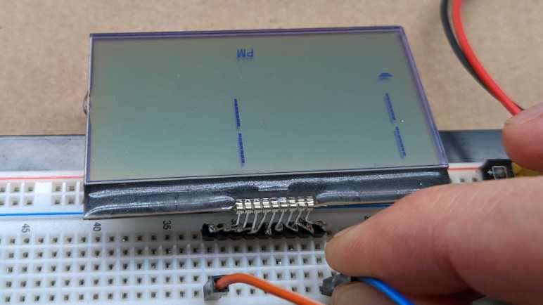
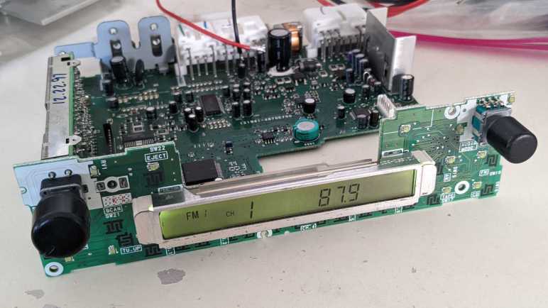
It appears two of my salvaged LCDs might have come from the same product, with identical (or nearly so) interface and command protocol. That is great, but I don’t know what that protocol actually is. It isn’t terribly promising as a starting point, so I decided to continue looking in my pile of salvaged electronics. Next candidate is the LCD embedded in the control panel of an automotive audio head unit. This was a stock tape deck from a 1998 Toyota Camry LE, which was replaced by an aftermarket deck for modern conveniences like Bluetooth audio. It was one of the retired pieces of equipment I brought to the January 2020 session of Disassembly Academy and taken apart. All metal pieces went into recycle, all plastic pieces went to landfill, and I kept the electronic circuit boards.

Since the metal external panels are gone, I no longer have the model number. Searching through eBay listings, I guess it was a Toyota 86210-08010. This listing explicitly mentioned Toyota Camry in their description. However, I saw several other Toyota units that looked superficially similar but with different numbers, like this 86120-04090. I thought maybe I’ll just call it “86210” but there are “86210” units that look wildly different like this 86120-2B761. Clearly there are complexities in Toyota parts numbering that I don’t understand, but for now I’ll go with 86210-08010.

The reason this particular LCD is interesting is because it is part of a still-intact control board. I’m optimistic that I could figure out enough of the control board to make it do my own bidding.

The backside of the board has a large identifier: 121941-4890D700. That didn’t turn up anything, but there are two other features on the back that make me optimistic.

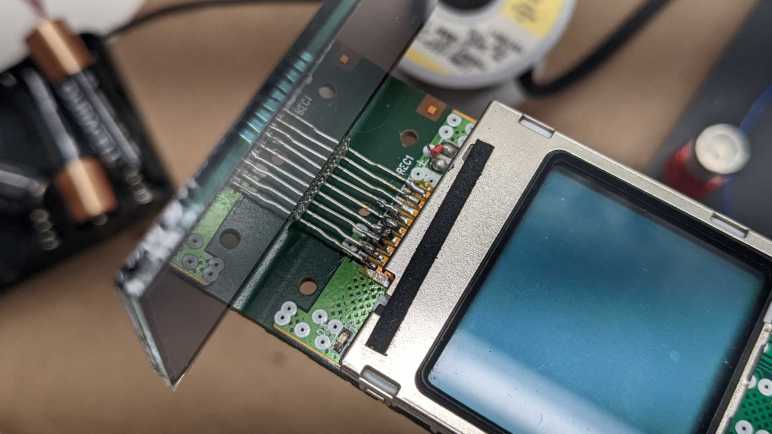
The first is a clearly identified chip: Sanyo LC75853N and a search found its datasheet. It is a LCD controller with additional capability to scan for button presses, which makes sense for use in a control panel like this one. Furthermore, the datasheet should describe the control protocol.

Even better, the board has a connector to the rest of the radio, and it looks like all the pins are labeled. Some of them were cropped at the bottom and even if they weren’t cropped, I don’t necessarily understand what they all mean. But GND and ACC5V are clearly legible, which is a great start. What more can I ask for? Well, I can ask for it to be powered up and running so I can probe those pins in action.

When I replaced this head unit, I recall going online to purchase an adapter wiring harness and a pinout guide to know which wire went where. Many Toyota head units shared the same connector and pinout, so this diagram for a slightly different model was close enough.

I could buy another wiring harness, possibly this unit, but decided against spending more money. This is for experimentation and I could easily solder directly to the circuit board.

It probably didn’t matter very much in this case, but I also thought I’d follow wire color convention for automotive audio. I connected the “battery” (yellow) and “accessory” (red) wires up to +12V on my bench power supply, and black wires to ground.

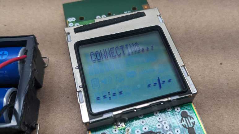
The screen comes alive! Very nice. From here, I started disconnecting power wires and found that for purposes of powering up the control panel I only really needed half the wires, the three on the central connector. (Visible in the back of this image.) With a screen that is alive and kicking, and a datasheet that should explain everything, I expect a high probability of success for learning how to master this control board. This could be an interesting project, and the only problem is that it veers very far from Joey Castillo’s Remoticon talk which motivated me to look at LCDs. I set aside this project for later and started looking for simpler LCDs in my pile.


[UPDATE: I have returned to this device and made great progress on the second try.]

Risky Parallel LCD Test Surprisingly Worked

I briefly surveyed LCD controllers popular with hobbyist projects, hoping to find something that might match my mystery salvaged LCD units on hand. No luck. If my intention is to build a project with LCD screen, I should go and buy one of those popular units. But the point of the exercise is to try reusing salvaged electronics, so I stared at my two LCD units some more while thinking of Emily’s observation that they both had nine interface pins and the hypothesis they share a common command set.

I know for sure they aren’t identical. For starters, the two modules are different sizes. And while they both have nine interface connection; they are physically different. The bare LCD module has pins, and the headset LCD module is soldered to its circuit board with a segment of FPC (flexible printed circuit). Holding the bare LCD’s pins up to those soldered joints, I had an idea: what if I wired both LCDs together in parallel by soldering the bare LCD pins to the existing FPC pads?

The first thought was to dismiss it as a stupid idea. There were too many reasons why it wouldn’t work even if the devices have a common interface. If they were SPI devices, they would conflict on the MISO pin. If they were I2C devices, the two devices probably have different addresses, and the bare LCD wouldn’t do anything. Or if they had the same address, there would be conflict as they both tried to ground I2C control lines at the same time. LCD controllers like the PCD8544 had internal LCD voltage generators. Wiring two boost converters in parallel risks creating a feedback cycle that overshoots limits and destroy components. And if their wiring were completely different, I risk short-circuiting VCC to ground, or possibly connecting one of the boosted higher voltage lines to something that could not tolerate such voltage. And I’m sure there are other risks that didn’t come immediately to mind.

But despite all those risks, the thought refused to go away. After a day of “but what if?” ringing around in my head, I decided these were salvaged components that I would eventually discard if I couldn’t figure them out. (Or even if I could, if I’m being honest.) Basically, I didn’t have anything to lose by throwing the dice and trying parallel wiring.

I powered on the handset LCD and, after a few seconds, the screen came up. It was quite faded compared to earlier, so something in this circuit is unhappy with the parallel screens. But at least I didn’t kill it outright.

With a mental drum roll, I tilted my head to look at the other screen and… wow! I see something!

Both screens are very faded compared to what I’ve seen them earlier, but they are both nominally working while wired in parallel which is amazing! Seeing same text on both indicates the alphanumeric portions are common. The segmented portions below “CONNECTING…” are, however, different between the two displays.

The faded contrast tells me something is overstressed, so I quickly powered down after taking these pictures and de-soldered the second LCD. Powering the board back up restored normal contrast on handset LCD implying there was no permanent damage.

While there doesn’t seem to exist a popular common protocol for nine pin LCDs, at least these two are in common with each other. From a historical perspective, their commonality implies the bare LCD was salvaged from the base station for the wireless handset. From a reverse engineering perspective, having two devices with a common protocol meant I could leave the handset LCD intact for probing. I could then test my guesses with the bare LCD connected to another microcontroller. From a reuse perspective, it means if I’m successful figuring these guys out, that work could be utilized on two displays and not just a one-off. I could work on this project, but instead I decided to dig up another LCD that should be easier to decipher.

Hobbyist-Friendly LCD Controllers

When I dug up my collection of salvaged LCDs, I had expected to find bare arrays that I could power directly. But the first two units I probed turned out to have a controller embedded in the display. The good news is that I wouldn’t have to worry about complex multiplexing AC signals, the bad news is that the problem shifts to deciphering a digital communication protocol. With this switch, I decided it would be wise to pause and take a look at existing information on LCD controllers.

I’m excluding controllers dealing with large LCD arrays like those on computer and television screens, or even modern high resolution touchscreen phones, as they have signal requirements that exceed my current electronics skill. I’m starting at the lower end of the spectrum where they are accessible to the electronics hobbyist. The field appears to be dominated by two classics: the PD8544 and the HD44780. Both of these designations refer to specific products, but due to their popularity, they have become de facto generic names covering the many clones and compatible controllers that also exist.

Anyone who remembers Nokia’s classic snake game has spent time staring at a PCD8544-controlled LCD. Sometimes called the Nokia 5110 LCD, after the phone that introduced faceplate customization. PCD8544 was the brains literally behind the dot matrix screen on classic Nokia phones. Once the market moved to large touchscreens, a lot of Nokia phones were retired, making these screens easily and cheaply available for hobbyists. The bad news is that old Nokia bricks are no longer found in a drawer in every house, it’s been too long. The good news is that the display can still be purchased in a hobbyist-friendly breakout board format.(*) There exists multiple Arduino libraries for drawing to such a screen. Reading Adafruit documentation, I see there are eight pins in the interface instead of nine on the screens I have. I had hoped maybe my screen is closely related to a PCD8544 with an extra pin for some additional feature, but if so, pin orderings have been switched around as the VCC and GND pins are further apart. Fortunately the PCD8544 datasheet is widely available (here’s a mirror hosted by Adafruit) so it gives me an idea of what data stream for a SPI-controlled LCD looks like.

The other LCD controller targeted by several different Arduino libraries is the HD44780, an LCD dot matrix display tailored for showing alphanumeric characters. Making it very popular for devices that need to show a few words to the user, anything from household appliances to industrial machinery. It’s not technically a graphics display, but it can be hacked to show graphics via “custom fonts”. This ability to range from easy text output to complex graphics hacks make them a good choice for hobbyist projects, as they are sold in project-friendly format and easily affordable (*). Another (admitted flawed) metric of popularity is that somebody saw fit to write a Wikipedia page for HD44780, an honor granted to few other LCD controllers.

Could my salvaged display be a HD44780 compatible unit? First glance says no: the typical wiring requires 16 pins. A closer look gave me a bit of hope, as two of those pins may be absent for units without built-in backlight, bringing it down to 14 pins. There’s also a 4-bit operation mode, dropping it down to 10 pins. Removing just one more pine would bring it down to 9, but even then, it requires four data lines and my display uses two. For this reason I don’t expect much resemblance between my salvaged LCD controller and a HD44780. There are many other Arduino libraries for different LCD modules, but I didn’t know how to further narrow down the possibilities. Aside from laboriously searching through every pinout diagram in documentation, which I’m not inclined to do right now.

Looking at my other favorite prototyping ecosystem, ESPHome also has support for the Nokia-popularized PCD8544, though not the HD44780. Other units supported under their Display Components umbrella are mostly I2C and SPI devices plus a few UART controlled units sprinkled in between. They all use fewer than nine pins. However, they did remind me of the SPI protocol which makes me think my salvaged LCD may be a SPI unit. The two data lines may be MISO and MOSI pins. (The PCD8544 appears to be a SPI device without MOSI.)

A web search for “nine pin LCD” found this electronics StackExchange question titled Do 9 pin LCD modules have a standard interface? Sadly, the answer appears to be “No”. The specific example in this thread was identified as a UC164904, which is a SPI device plus extra pins like two for LED backlight control. As my particular unit had an external backlight, it is definitely not a UC164904.

If information on my LCD unit is to be found online, I will need to be more specific than “it has nine pins”. But if they both have nine pins, perhaps they’re controlled the same way? I tried the easiest (and pretty risky) test that came to my mind and was surprised when it worked.

Landline Answering System Handset LCD (CL84209)

For years I’ve been salvaging LCD from electronics I took apart for fun, and I’m finally getting around to playing with them. The first example was too much of a mystery for this beginner to tackle, so I set it aside and dug up another unit from my salvage pile.

This LCD is still attached to its circuit board, which gives me more information to work with. Most everything else are gone, but I can see clear indications of a keypad underneath the screen. Two large metal contacts at the bottom hint at a rechargeable device.

A sticker on the back side gave me definitive information of “Model#: CL84209”. That quickly led to a long-discontinued product: a landline phone system that has an answering machine built-in the base station and supports multiple remote wireless handsets we can place elsewhere in the house.

Amusingly, the best picture I found was from an eBay listing of its product box. The circuit board on hand is consistent with wireless handsets visible in that picture. Since I was on eBay, the “related items” list included some replacement batteries for this handset. It appears to be two NiMH AAA-sized battery cells in series, which preemptively answered what would have been my next question for powering it up.

I connected two rechargeable NiMH AA cells in series and wired that to the handset’s battery terminals. After a few seconds for system startup, I’m rewarded with an active and running LCD displaying “CONNECTING…” as this handset makes its futile attempt to connect to its base station. This is a pretty good starting point. Leaving the phone running, I probed the nine pins exposed above the display. Lacking official documentation, I arbitrarily numbered them left to right:

Their voltage readings relative to battery negative were:

  1. 3.33V rock solid.
  2. 3.1 – 3.3 V, jumps around at semi regular intervals.
  3. 2.9 – 3.3 V, also jumping around.
  4. 0V
  5. 3.2 – 3.3 V
  6. 6.55 V
  7. 4.92 – 4.94 V
  8. 1.66 V
  9. 5.59 V

From this information I inferred that there are boost converters on this circuit board to deliver these voltages from the 2.4V nominal power of a pair of NiMH batteries. Pin 4 is the only candidate for GND pin. The steady 3.33V of pin 1 makes it the best candidate for Vcc, with the runner-up candidate of pin 5 which is also 3.33V but not as steady. Pins 6 and 9 were unexpected, I hadn’t considered the possibility a LCD might need to be fed multiple voltage planes, but it sure looks that way right now.

I then switched to my cheapo single-channel oscilloscope, which is no longer reliable in voltage ranges but still useful for visualizing waveforms. Pins 2 and 3 receive bursts of square waves that indicate data pins, explaining their voltage variation. Pins 7 and 8 have regular square waves that are consistent with clock pins, but since I have just a single channel oscilloscope, I don’t know how the two signals relate to each other. It is weird to me that they show up as two very different voltage ranges on the voltmeter. The rest of the pins didn’t look very interesting under an oscilloscope in the ~millisecond range, though it’s possible they are changing either much slower or faster than that time range or need other conditions to change.

I guess the next thing to do is to connect at least pins 2 and 3 to a logic analyzer to dump the raw data, but I have no confidence I can make heads or tails of the raw bit stream. I see no identifying markers on this particular LCD, either. It’s possible some information is blocked by the circuit board, but I’m not yet ready to risk destruction of this LCD pulling it off this circuit board. Bouncing ideas off Emily Velasco, she called attention to the fact that both this LCD (on a circuit board) and the earlier LCD (without a circuit board) both had nine interface pins. Maybe there is a popular common LCD controller with nine interface pins? Time for a bit of research.

Mystery Desk Phone LCD

After learning some basics of driving small segmented LCD units from Joey Castillo’s Remoticon talk, I started digging through my pile for LCDs I had salvaged in past teardowns because I thought I would play with them later. “Later” is now.

I chose this as the first candidate because it had metal pins for connectivity instead of the elastomeric “zebra strip” commonly used for LCDs. (Like the LCD in a food thermometer I recently took apart.) I hoped metal pins meant it would be easier to work with. I vaguely remember salvaging this unit from a landline office desk phone using my paint-stripping heat gun. I have little memory of the rest of the device, but I clearly remembered this screen had a LED backlight whose plastic bits melted out of shape when I tried to salvage it. Rendered useless by my mistake, I discarded the backlight. I have better tools and skills to remove that sort of stuff now, but that’s history so moving on.

Like I said I wasn’t terribly meticulous when salvaging this LCD, so I’m missing a lot of information about it. I didn’t write down the make and model of the phone or noted any information about the circuit board. (Useful for determining ground pins and such.) And now I’m faced with essentially a black box as there were minimal markings on the LCD.

One corner had a logo with “LCD” in the middle. Could it be the logo of a manufacturer who believes that the fact they make LCDs is more important than their own name? Seems odd but stranger things have happened. (U.S. Robotics made no robots but was named because founders were fans of Issac Asmiov.) Next to that logo is a number 6334 that might be a model number but that is too generic for me to find anything online.

Another corner had information etched into the glass. I read them as:

A200910072(R)
0944851649

The nature of this information implies something that changes rapidly instead of a make and model. 20091007 conceivably stands for a production date of October 7th, 2009. The second row may be a serial number. None of which, sadly, helped me find more information about it.

Below the etched layer, I think I see “1B” which is likely on the same layer as “LCD 6334” earlier.

I then decided to probe these pins with an “AC” signal as per Joey Castillo’s talk. I thought it would be helpful to solder them to a set of 0.1″ pitch breadboard compatible header pins. With nine pins, I had hoped this was a very simple segmented LCD status indicator. Maybe a few phone-appropriate icons like “on hold”.

Probing various combinations of pins, the most response I could get out of the device is captured in this photo, and only for a few seconds before it faded out. I see a “PM” that would be appropriate for a clock, and a single trapezoid that could be a 7-segment numerical display to go with that clock. But more significantly, I see hints of a large dot matrix display with four separate lines of seven segments each. The information visible here implies a far more complex display than what could be multiplexed with just nine pins. This is not a bare LCD with pins for an external driver, there must be a controller chip under the black blob of epoxy.

But if that is a controller chip, how did I manage to darken a few elements by probing with AC? A wild guess is one of these two pins (leftmost or rightmost) is a data clock pin. Absent actual connection to VCC or GND, the chip was running on the minimal power flowing on those two pins. After a few seconds in the absence of an actual ground, some internal element became saturated and stopped working. If I wait a few minutes for that condition to fade, I can reapply these pins and light up the same elements again. So the good news is that I don’t think I broke the LCD, but I certainly wasn’t running it under any semblance of control.

I don’t think I can do much more with this LCD right now. More skilled hardware hackers have techniques to tease out roles for these nine pins, but that is beyond my skill at the moment. I thought reverse engineering might be easier if I could probe the associated circuit board, so I pulled out an LCD still attached to its board.

Inspired by Joey Castillo’s Introduction to Segmented LCD

When I have a laptop LCD display panel less than full HD (1920×1080) resolution I have resorted salvaging just their LED backlights and discarding the rest. I considered these panels in an awkward zone where the data signal requirements are too high to be practical for me to drive with my own electronics projects, and their resolution too low to justify spending money to buy a driver board.

But computer screens aren’t the only liquid-crystal displays, we are surrounded by numerous smaller and simpler LCD used in household electronics. For many years I had the intent to learn how to reuse them, but I never got around to putting any effort into it. Until I watched Joey Castillo’s talk at Hackaday Remoticon 2021. The topic of this talk: repurposing segmented LCD of wristwatches like the classic Casio F-91W, which covers some general information on LCD in general.

Most importantly, it covered some of the basics from an electronics hobbyist perspective, which was missing from the general Wikipedia page for LCD. I was encouraged to see that the wiring multiplex scheme usually resembles what I’m already familiar from common-anode/common-cathode LED arrays. I was initially dismayed to learn that dedicated segment LCD driver modules apply alternating voltage on several voltage planes, which is a hassle to do with microcontroller general purpose IO pins. But good news! For the purpose of probing and experimentation, we can use two microcontroller GPIO pins and alternatively raising one pin while lowering the other. This, I can do.

After watching the video, I went online looking for more information on the topic. I found things like this Electronics StackExchange thread “How does a microcontroller drive an LCD?” and “Found an old LCD in an old radio, how to test it?” I also found things like this Atmel application note AVR241 “Direct driving of LCD display using general IO” for directly driving a simple segment LCD without a dedicated peripheral. They all line up with the broad strokes of Joey’s Remoticon talk, making me feel encouraged enough to start digging up some salvaged LCD to see if I can make anything happen.