Adafruit Memento + AMG8833: Upgrade Scotch Tape to Servo Tape

I taped an AMG8833 thermal sensor to my Adafruit Memento camera to create a thermal vision camera, and finally got my code fast enough to keep up with the sensor’s speed limit at around ten frames per second. It turned out to be a great practice lesson in CircuitPython performance optimization! Now I need to wrap up some loose ends.

There was one little change on the software side: because I’m using color to represent temperature, sometimes color in the real world can be confusing. So I flipped the visual camera mode to black-and-white ensuring all color visible on screen comes from thermal data.

Then I worked on improving how the AMG8833 is mounted. I used cellophane tape because it was quick and easy and good enough for me to start experimenting. But it’s pretty fragile and would not fit in the Memento carrying case that came as part of Adabox 021. Now that the experiment is a success, it’s worth effort to make a better mount.

The sensor is now protected by a bit of transparent heat-shrink tubing, and the wires were re-soldered so they exit out the side instead of back.

I then used some double-sided foam tape to attach the sensor module closer to the visual camera module. This position blocked three of the front panel LEDs but I haven’t been using them anyway.

And now it fits in carrying case! I thought having a thermal camera would be neat, but I was never sure how much I would actually use one. Now I have a low resolution DIY version, I’ll see if it comes in handy. I can see several future possibilities:

  1. I might take this apart for another project idea. For one thing, this project didn’t make use of Memento’s photography capabilities at all and I think that’s a shame.
  2. Maybe I’ll upgrade to a better sensor module breakout board.
  3. Maybe I’ll decide a thermal camera is useful enough to finally buy a FLIR ONE for myself.

Time will tell.

For now, I’m still thinking about electronics that help me see what I can’t see with my own eyes. Thermal cameras do that, and so do microscopes.

Adafruit Memento + AMG8833: NumPy and List Comprehension

Pairing an AMG8833 thermal sensor with an Adafruit Memento camera gave me a thermal camera, but my code was running quite slowly. I found an example illustrating use of (ulab.numpy subset of) NumPy for interpolating data from AGM8833’s sensor grid to a larger grid, and adapted it to my project. My performance marker timers say this resulted in total of ~320ms per frame, or roughly 3 frames per second. Here’s an excerpt from rendering four frames:

read 38028 scaled 596 mapped 1520 blit 27626 grid 224501 refresh 24528 total 316799
read 38237 scaled 596 mapped 1520 blit 28789 grid 223636 refresh 24438 total 317216
read 38296 scaled 566 mapped 1580 blit 27567 grid 226170 refresh 24438 total 318617
read 38356 scaled 626 mapped 1728 blit 28849 grid 198901 refresh 24587 total 293047

More important than the interpolation itself was having an example for me to study NumPy. My takeaway is to avoid writing loops iterating through arrays as much as possible. Almost every performance win here boils down to substituting a tightly iterating loop with a single operation.

Bitmap as NumPy Array

The biggest win was converting my thermal overlay drawing commands into a single NumPy operation. The critical part is creating a ndarray view on top of existing bitmap data in order to avoid copying its bits around.

output_ndview = np.frombuffer(output_bitmap,dtype=np.uint16).reshape((240,240))

This was the key allowing me to describe large scale bitmap operations without having to write my own for loops to iterate over x,y coordinates. The loops are still happening, of course, but now they’re within fast native code free of Python runtime overhead.

Subset Blues

I knew ulab.numpy was a subset of full NumPy and was curious if the missing parts would be something I wished for or if they’re too esoteric and I wouldn’t miss their absence. The answer is the former: even as a beginner I quickly ran into situations where I found a NumPy answer on something like a Stackoverflow thread only to find features missing from ulab.numpy. One example is repeat(), which I replaced with my own series of unrolled copy operations.

List Comprehension For Palette Lookup

The final bit of code to be replaced by NumPy operations was a thermal color palette lookup. My first implementation did it easily with nested for loops iterating through x and y axis, but it’s not fast. This feels like an operation that might have a NumPy operator, but nothing in ulab.numpy sounded applicable. Full NumPy offers a way to execute an arbitrary Python function over every element in an array, but that was missing from ulab.numpy. After reading through several Stackoverflow threads I decided to create a list comprehension out of palette lookup and build a NumPy array around the list. I’ve already explained why I didn’t like list comprehensions, but performance numbers don’t lie: performing palette lookup via list comprehension was at least an order of magnitude faster. For that kind of gain, I’ll hold my nose and use a list comprehension.

Final Results

I’ve replaced almost every for loop in my old code with NumPy operations, the only remaining inner loop for generates my list comprehension. All of these changes add up to quite an improvement. As can be seen in these times involved in generating four frames:

read 38624 scaled 775 interpolated 1132 mapped 2444 blit 28551 grid 6199 refresh 25361 total 103086
read 38624 scaled 626 interpolated 924 mapped 2175 blit 28730 grid 33319 refresh 25153 total 129551
read 38594 scaled 685 interpolated 1043 mapped 2295 blit 27716 grid 6288 refresh 25452 total 102073
read 38504 scaled 656 interpolated 924 mapped 2295 blit 28044 grid 33289 refresh 25213 total 128925

As low as 102ms, almost 10fps, which is great! In fact, it marks the finish line. 9-10fps is as fast as the AMG8833 can deliver due to legal limitations imposed on thermal sensors. Going faster won’t gain anything thus ends this practice session of CircuitPython performance optimization. I will wrap up a few details and move on to the next project.


https://github.com/Roger-random/circuitpython_tests/blob/main/pycamera_amg88xx/code.py

Adafruit Memento + AMG8833: Add Interpolation

I paired an AMG8833 thermal sensor with my Adafruit Memento camera to build a thermal camera. I expected it to be an instructional learning project, I just didn’t expect it to be a learning project about CircuitPython performance. First step was to add performance timers to quantify impact of future enhancements, which gave me a baseline. Here’s an excerpt reflecting four frames rendered using TileGrid:

read 38087 scaled 3099 mapped 1789 grid 1728 blit 28223 refresh 360370 total 433296
read 37789 scaled 3099 mapped 1759 grid 1758 blit 30190 refresh 359803 total 434398
read 38713 scaled 3129 mapped 1788 grid 1729 blit 29683 refresh 362098 total 437140
read 38296 scaled 3129 mapped 1758 grid 1759 blit 29146 refresh 360579 total 434667

Total time per frame of roughly 430ms means a little over 2 frames per second.

Back to Bitmap

I converted the code back to my naive dot-drawing code, which showed better numbers. Again, an excerpt of four frames:

read 37760 scaled 3368 mapped 1609 blit 27239 grid 146836 refresh 24468 total 241280
read 38266 scaled 3099 mapped 1580 blit 27239 grid 118077 refresh 24557 total 212818
read 38206 scaled 3368 mapped 1609 blit 27746 grid 144750 refresh 24527 total 240206
read 38237 scaled 3367 mapped 1610 blit 27269 grid 144750 refresh 24378 total 239611

My dot-drawing code is within the “grid” bracket and that’s why it got a lot slower. And “refresh” is technically wrong as I’m no longer calling display.refresh(). I’m actually calling pycam.blit() but since I’m already using the “blit” label for something else I left the label as “refresh”.

At a total cycle time of under 240ms, this was about 4 fps and almost double the speed of my TileGrid version. This is still very slow but the good news is the slowest parts are now code under my control.

Add Interpolation

With code under my control, NumPy experiment begins. I started by adapted PyGamer Thermal Camera code to my project. It replaced my old code within “scaled” and output a 15×15 array of interpolated values. Despite this added functionality, execution time dropped from ~3.3ms to ~0.6ms. Nice!

Unfortunately overall frame rate dropped from ~4fps to ~3fps because “grid” got slower: it now has to draw a thermal overlay of 15×15 data points instead of just 8×8.

read 38028 scaled 596 mapped 1520 blit 27626 grid 224501 refresh 24528 total 316799
read 38237 scaled 596 mapped 1520 blit 28789 grid 223636 refresh 24438 total 317216
read 38296 scaled 566 mapped 1580 blit 27567 grid 226170 refresh 24438 total 318617
read 38356 scaled 626 mapped 1728 blit 28849 grid 198901 refresh 24587 total 293047

Slower frame rate is only a temporary setback, because this example helped me learn how (the ulab.numpy subset of) NumPy can be applied to my project. These lessons helped me unlock additional performance gains.

Adafruit Memento + AMG8833 Overlay: Performance Timers

I’ve successfully overlaid data from a AMG8833 thermal sensor on top of the Adafruit Memento camera viewfinder, turning it into a thermal camera. A very slow and sluggish thermal camera! Because my first draft was not written with performance in mind. To speed things up, I converted my thermal overlay to use TileGrid and take advantage of the compositing engine in Adafruit’s displayio library. In theory that should have been faster, but my attempt was not and I didn’t know how to debug it. I went looking for another approach and found MicroPython/CircuitPython has ported a subset of the powerful Python NumPy library as ulab.numpy. And furthermore, there was an example of using this library to interpolate AGM8833 8×8 data to a 15×15 grid in Adafruit learning guide Improved AMG8833 PyGamer Thermal Camera. Ah, this will do nicely.

Add Performance Timers

The first thing I got from that project is a reminder of an old lesson: I need to record timestamps during my processing so I know which part is slow. Otherwise I’m left with vague things like “TileGrid didn’t seem much faster”. I added several lines of code that recorded time.monotonic_ns() and a single line at the end of my loop that print() delta between those timestamps. Since the units are nanoseconds and these are slow operations, I get some very large numbers that were unwieldy to read. Instead of dividing these numbers by 1000, I right-shifted them by 10 bits to result in a division by 1024. The difference between “roughly microseconds” and “exactly microseconds” is not important right now and, in the spirit of performance, should be much faster.

Measure TileGrid Implementation

Here’s are four frames from my TileGrid implementation:

read 38087 scaled 3099 mapped 1789 grid 1728 blit 28223 refresh 360370 total 433296
read 37789 scaled 3099 mapped 1759 grid 1758 blit 30190 refresh 359803 total 434398
read 38713 scaled 3129 mapped 1788 grid 1729 blit 29683 refresh 362098 total 437140
read 38296 scaled 3129 mapped 1758 grid 1759 blit 29146 refresh 360579 total 434667

With a total of ~434ms per loop, this is just a bit over two frames per second. Here’s the breakdown on what those numbers meant:

  • “read” is time consumed by reading 8×8 sensor data from AMG8833 sensor. This ~38ms is out of my control and unavoidable. It must occur for basic functionality of this thermal camera.
  • “scaled” is the time spent normalizing 8×8 sensor data points between the maximum and minimum values read on this pass. This ~3ms is my code and I can try to improve it.
  • “mapped” is the time spent translating normalized 8×8 sensor data into an index into my thermal color palette. This ~1.7ms is my code and I’m surprised it’s over half of “scaled” when it does far less work. Perhaps ~1.7ms is how long it takes CircuitPython to run through “for y in range(8): for x in range(8):” by itself no matter what else I do.
  • “grid” is the time spent updating TileGrid indices to point to the color indices calculated in “mapped”. Since it’s basically the same as “mapped” I now know updating TileGrid indices do not immediately trigger any bitmap processing.
  • “blit” copied OV5640 sensor data into a bitmap for compositing. This ~30ms is out of my control and unavoidable. It must occur for basic functionality of this thermal camera.
  • “refresh” is where most of the time was spent. A massive ~360ms triggered by a single line of my code. This included pulling bitmap tiles based on TileGrid indices, rendering them to the TileGrid, compositing thermal overlay TileGrid on top of the OV5640 bitmap TileGrid, and finally send all of that out to the LCD.

Back to Bitmap

I don’t know why my TileGrid compositing consumed so much time. I’m probably doing something silly that crippled performance but I don’t know what it might be. And when it’s all triggered by a single line of my code, I don’t know how to break it down further. I will have to try something else.


https://github.com/Roger-random/circuitpython_tests/commit/1a62d8adbbeecf9d05ad79ff239906367fbfb440

Adafruit Memento + AMG8833 Overlay: TileGrid

By overlaying data from AMG8833 thermal sensor on top of the Adafruit Memento camera viewfinder, I’ve successfully turned it into a thermal camera. The bad news is all of my bitmap manipulation code runs very slowly, bogging the system down to roughly a single frame per second. I blame my habit or writing Python code as if I were writing C code. Running tight loops shuffling bits around is fine in C, but now the same approach is incurring a lot of Python runtime overhead.

As I understand Python, the correct approach is to utilize libraries to handle performance-critical operations. My Python code is supposed to convey what I want to happen at a higher level, and the library translates it into low-level native code that runs far faster. In this context I believed I needed CircuitPython displayio sprite compositing engine to assemble my thermal overlay instead of doing it myself.

The viewfinder image is pretty straightforward, loading OV5640 into a Bitmap which went into a TileGrid as a single full-screen entry. The fun part is the thermal overlay. I created a TileGrid of 8×8 tiles, matching thermal sensor output data points. I then created another bitmap in code corresponding to my range of thermal colors. I didn’t see any option for alpha blending in displayio and, as I believed it to be computationally expensive, I wanted to avoid doing that anyway. My palette bitmap is again a screen door of my thermal color alternating with the color marked as transparent so viewfinder image can show through.

In theory, this means every thermal sensor update only requires updating tile indices for my 8×8 TileGrid, and displayio will pull in the correct 30×30 pixel bitmap tile to use as a sprite rendering my 240×240 pixel thermal overlay. The underlying native code should execute this as native code memory operation far faster than my loop in Python setting bitmap pixels one by one.

I had high hopes, but I was hugely disappointed when it started running. My use of TileGrid did not make things faster, in fact it made things slower. What went wrong? My best hypothesis is that compositing tiles with transparent pixels incur more workload than I had assumed. I also considered whether I incurred color conversion overhead during compositing, but as documentation for displayio.Palette claimed: “Colors are transformed to the display’s format internally to save memory.” So in theory color conversion should have been done once during startup when I created the thermal color tiles, not during the performance-critical loop.

The upside of Python’s “offload details to libraries” approach is that I don’t have to understand a library’s internals to gain its benefits. But the corresponding downside is that when things go wrong, I can’t figure out why. I have no idea how to get insight into displayio internals to see what part of the pipeline is taking far longer than I expected. Perhaps I will eventually gain an intuition of what is quick versus what is computationally expensive to do in displayio, but today it is a bust and I have to try something else.


https://github.com/Roger-random/circuitpython_tests/commit/650f46e64bc08de9f8c1f451a4d18ea7021e92fb

Adafruit Memento + AMG8833 Overlay: Alpha Blending

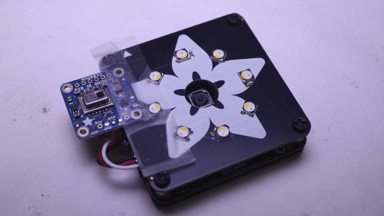
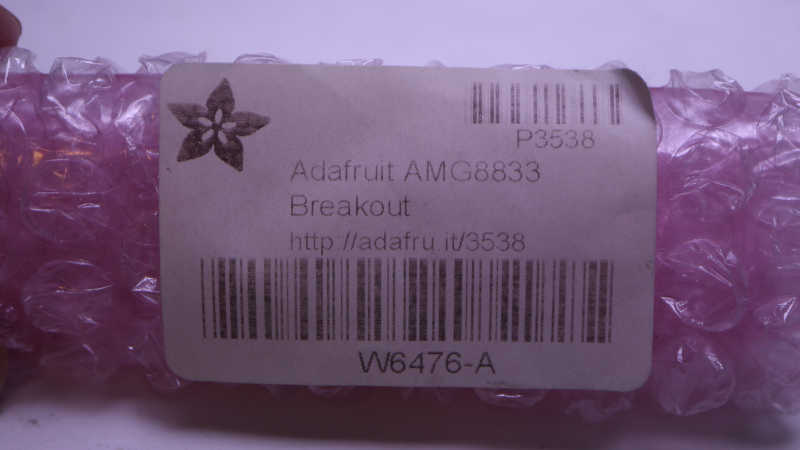
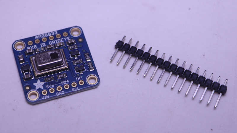
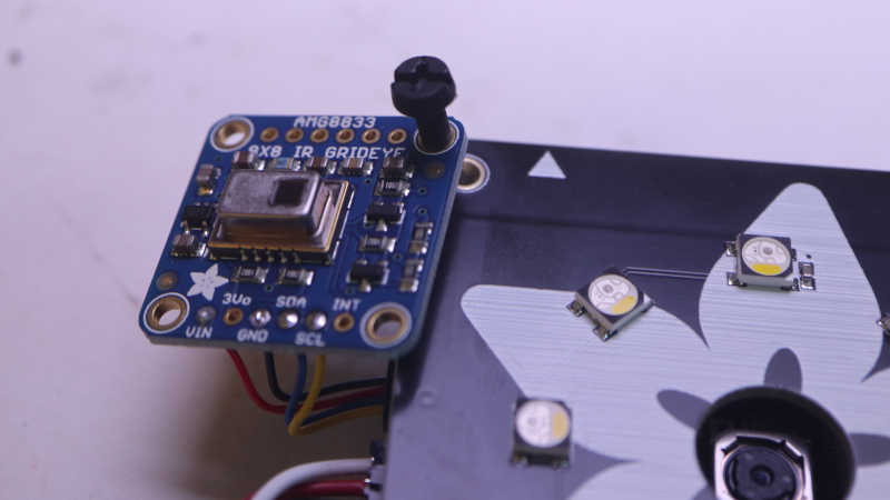
The AMG8833 thermal sensor I taped to an Adafruit Memento camera is successfully communicating with the ESP32-S3 microcontroller running Memento, and I can start working on integrating data from both thermal and visual cameras.

Goal

Low resolution thermal data can be difficult to decipher, but overlaying low-resolution thermal data on top of high-resolution visual data helps provide context for interpretation. This is a technique used in commercial thermal imaging products. The most accessible devices are designed to plug into my cell phone and utilize the phone for power and display. For my Android phone, it’ll be something like this FLIR One unit.(*) I’ve thought about buying one but never did. Now I will try to build a lower-cost (though far less capable) DIY counterpart.

Precedence

For code functionality, there’s a useful precedence in Adafruit’s “Fancy Camera” sample application: it has a stop-motion animation mode which shows the previously captured frame on top of the current viewfinder frame. This allows aspiring stop-motion animators to see movement frame-to-frame before committing to a shot, but I want to try using its overlay mechanism for my purposes. On the source code side, this means following usage of the data objects last_frame and onionskin. They led me to bitmaptools.alphablend(). Performing alpha blending on a microcontroller is not fast, but it was a good enough starting point.

Drawing Thermal Overlay

Now that I’ve found a helper to blend the viewfinder image with my thermal data, I have to draw that thermal data. The small LCD on board Memento has a resolution of 240×240 pixels, and that divides neatly into 8×8 sensor resolution. Each sensor data point corresponds to a 30×30 pixel block of screen. Drawing solid squares was really, really slow. I opted to draw every third pixel vertically and horizontally, which means drawing a dot for every 3×3=9 pixels. This lent a screen door effect to the results that was, again, good enough as a starting point.

Thermal Color Spectrum

Commercial thermal cameras have established a convention for color spectrum representing thermal data. Black represents cold, blue is a bit warmer, then purple, red, orange, yellow, all the way to white representing the hottest portion of the picture. I started mapping out a series of RGB values before I noticed that spectrum is conveniently half of a HSV hue wheel. I went looking for a CircuitPython library for HSV color space and found FancyLED. Calling pack() gave me a representation in RGB888 format instead of the RGB565_SWAPPED format used by Memento LCD. I didn’t find an existing conversion utility, but I’m a C programmer and I’m comfortable writing my own bit manipulation routine. It’s not the fastest way to do this, but I only have to build my palette once upon startup so it’s not a concern for the performance-critical inner display loop.

    # Obtain hue from HSV spectrum, then convert to RGB with pack()
    rgb = fancy.CHSV(hue, saturation, value).pack()

    # Extract each color channel and drop lower bits
    red =   (rgb & 0xFF0000) >> 19
    green_h3 = (rgb & 0x00FF00) >> 13
    green_l3 = (rgb & 0x003800) >> 11
    blue =  (rgb & 0x0000FF) >> 3
    # Pack bits into RGB565_SWAPPED format
    rgb565_swapped = (red << 3) + (green_h3) + (green_l3 << 13) + (blue << 8)

Orientation

I was happy when when I saw my thermal color overlay on top of the viewfinder image, but the two sets of data didn’t match. I turned on my soldering iron for a point source of heat, and used that bright thermal dot to determine my thermal sensor orientation didn’t match visual camera orientation. That was easily fixed with a few adjustments to x/y coordinate mapping.

Field of View

Once the orientation lined up, I had expected to adjust the scale of thermal overlay so its field of view would match up with the visual camera’s field of view. To my surprise, they seem to match pretty well right off the bat. Of course, this was helped by AGM8833’s low resolution giving a lot of elbow room but I’m not going to complain about having to do less work!

Too Slow

At this point I had a first draft that did what I had set out to do: a thermal overlap on top of visual data. It was fun taking the camera around the house pointing at various things to see their thermal behavior. But I’m not done yet because it is very sluggish. I have plenty of room for improvement with performance optimization and I think TileGrid will help me.


(*) Disclosure: As an Amazon Associate I earn from qualifying purchases.

https://github.com/Roger-random/circuitpython_tests/commit/30e24717cad579a0cc05f4b381d5f637259fe4bb

Adafruit Memento + AMG8833 Initial Bootstrap

I’ve taped an AMG8833 thermal sensor to the side of an Adafruit Memento camera, just a quick hack for mechanical attachment while I experiment. I want to get them to work together and show something interesting, which means I need to figure out the software side. Here were my initial bootstrap steps:

Boarding An Existing I2C Bus

The first test was to see if the device is properly visible on Adafruit Memento’s I2C bus. Adafruit sample code failed when it tried to create a I2C busio object because it was written with an implicit assumption the AMG8833 was the only I2C device present. When mounted on an Adafruit Memento, I need to grab the existing I2C object instead of creating a new one.

Data Elements Are Floating Point Celsius

One thing that I didn’t see explicitly called out (or I missed it) was the format of data points returned by calling Adafruit library. Many places explaining it will be an 8×8 list of list. That is, a Python list of 8 elements where each of those elements is a list of 8 data points. But what are the individual data points? After printing them to console I can finally see each data point is a floating point number representing temperature reading in Celsius.

I2C Operation On Every pixels Property Getter Call

One lesson I had to learn was to be careful how I call the pixels property getter. One of the sample code snippets had this:

for row in sensor.pixels:
    for temperature in row:
        ...[process temperature]...

And while I was experimenting, I wrote this code.

for y in range(8):
    for x in range(8):
        sensor.pixels[y][x]

Conceptually they are very similar, but at run time they are very different. Mine ran extremely slowly! Looking at the library source code revealed why: every call to the pixels property getter initiates an I2C operation to read the entire sensor array. In the first loop above, this happens once. The second loop with my “write Python like C code” habit meant doing that 64 times. Yeah, that would explain why it was slow. This was an easy mistake to fix, and it didn’t take much more effort before I had a working first draft.

AMG8833 Module Finally Unwrapped

I’ve been learning CircuitPython library implementation for Adafruit Memento (a.k.a. PyCamera) with the goal of doing something interesting beyond published examples. After brainstorming a few candidates, I decided to add an AMG8833 thermal sensor alongside. Mainly because I bought an Adafruit breakout board thinking it was neat and had yet to unwrap it. Today is the day.

According to my Adafruit order history, I bought this way back in 2018. Look at how faded that label has become. Over the past six years several project ideas had come and gone, the most recent one I can remember being an ESP32 web app like what I had built for the AS7341 spectral/color sensor. But none of them got far enough for me to unwrap this roll of pink bubble wrap.

Since the time I bought my sensor, Adafruit has added a higher-resolution thermal sensor to their product list. I told myself not to spend money on the newer fancier sensor until I actually use the one I had already bought. During this time Adafruit has also evolved the design, adding a STEMMA QT connector.

If I had one of the newer boards, I wouldn’t need to do any soldering. The Memento has a STEMMA QT port and this little cable would connect them together.

But since I have the old board, I cut the cable in half so I can solder wires and plug the other end into Memento.

For mechanical mounting, I thought I would use one of the existing mounting holes and bolt it to a Memento corner post. It’d be quick and easy but unfortunately the hole diameter is just a tiny bit too small for this idea to work.

With that idea foiled, my brain started thinking about alternate approaches that grew more and more elaborate. I didn’t want to invest in the time and effort because I didn’t even know if this idea would work. I taped it down for the sake of expedient experimentation until a proof-of-concept first draft is up and running. Time to start coding.