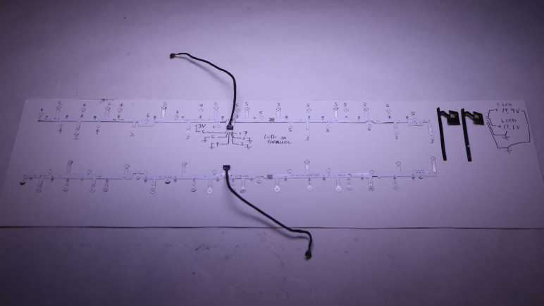
While doing a bit of work bench clean up, I found the LED arrays I had intended to salvage from my HP Windows Mixed Reality headset teardown. The surface mount LEDs were soldered on flexible circuit boards so they’re a bit too fragile for me to just toss them in a plastic bag. I found a piece of cardboard to serve as a backing and that should help. Before I put them away folded between sheets of cardboard, I thought I’d pull out my LED tester. Here’s what I found out about their pinout, in the hopes such information will be helpful for future project planning.

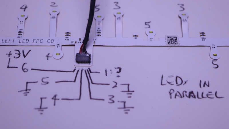
The two long strips came from handheld controller location beacon rings. Their shapes are symmetrically mirrored between left and right hand controllers, but they both use the same electrical connector. I saw a small arrow and decided that was pin 1, but it didn’t seem to connect to anything? Pin 6 is the common positive power supply, and pins 2 through 5 are grounds, one for each of four strings. Each string of LEDs are wired in parallel, so 3V is enough to start illuminating them with 20mA shared across all LEDs. There are resistors visible on board so current limiting seems to already exist if I’m ready to crank up the voltage. The LEDs are labeled D1 through D32. I had guessed these 32 LEDs would be evenly divided among 4 strings for 8 LEDs each, but it’s actually two strings of 7 and two strings of 9.
| Connector Pin# | LED Start | LED End | LED Count |
|---|---|---|---|
| 2 | D26 | D32 | 7 |
| 3 | D19 | D25 | 7 |
| 4 | D10 | D18 | 9 |
| 5 | D1 | D9 | 9 |
Using my mini hot plate I also salvaged the cable PCB connectors. I don’t know if I will use them, but I have the option to do so if I want. At the moment I’m not sure how I might utilize these two very irregularly shaped string of LEDs.

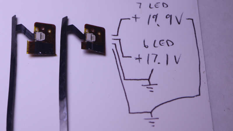
The two short strips came from visor LCD backlights. I wanted to keep the entire backlight display but it was so thin and delicate I failed to disassemble them intact. These LED strips are my consolation prize. Two identical units, one for each eye. Four pins on the connector for two LED strings, but again they are not equally sized. The inner pair powers a string of 6 white LEDs in series, around 17.1V DC for 20mA. The outer pair powers a string of 7 white LEDs in series, around 19.9V for 20mA. I don’t see current limiting resistors here so something else will have to keep things under control.
I thought about using my hot plate to pull these connectors from the flex circuit board as well, but decided to use scissors to cut off most of the flex circuit board and keep the connectors attached. I think this pair of ex-backlight LEDs will work well as PCB side lights, once I can think of a good design for a light-up PCB holder.
