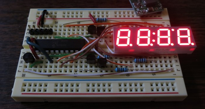
The KiCad Getting Started guide only covers the basics, but it’s enough to let the user embark on exploratory adventures to learn the rest of the tool piece by piece. I know I don’t have the knowledge and experience to do a good job at circuit design, but I’m a believer that such knowledge and experience is built up by learning from mistakes. So: let’s dive right in and try to implement the circuit board for my LTC-4627JR driver project and see what we learn.
The circuit diagram portion was relatively straightforward. Most of the lessons in the Getting Started guide applies, up to and including how to build a custom component for my schematic because the LTC-4627JR was not in the KiCad standard library. Somebody had built a library of components that included the LTC-4627JR, and made it available on Github. But this is a learning exercise and I wanted to learn how to do it myself.
The PIC16F18345 was not actually in the KiCad library, but a sibling part PIC16F18344 was available with a 20-pin DIP footprint, which is what I want right now. However, the eventual goal is to go to the surface mount version of the part and I hope I’ll be able to find another substitute with the same 20-pin SMD footprint.
There was no specific KiCad part for the 2N2222 transistor, but there are generic NPN transistors and I think that’s good enough. I was puzzled by the large number of options until I figured out they were different combination of a transistor’s pins. The three pins were labelled in order of pin number. So the variant tagged “BEC” has the base on pin 1, emitter on pin 2, and collector on pin 3. The “BCE” variant has the latter two pin swapped, etc. Looking at my 2N2222, I decided to use the EBC variant because that’s the order I see in the Wikipedia article.
The resistors were straightforward, as were the two I/O headers on the board. A four-pin connector for power, ground, and the 2 I²C wires. The five-pin connector is for the PICkit 3 to perform in-circuit programming.
From looking over schematics in the past, I got the distinct feeling of a stylistic convention for laying things out. Much like there are conventions for software source code. But a gut feel is not enough – I needed help from somebody to concretely spell out the rules. A web search for “circuit diagram conventions” pointed me to this article on Electronics StackExchange.
Armed with the list of conventions and a few hours to bump my head in KiCad, I got a passable basic schematic.

(The work described in this blog post are publicly available on Github.)


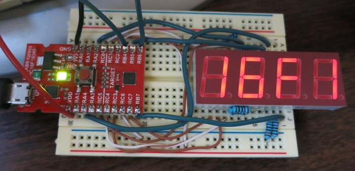
 Now that I have a rudimentary I²C implementation up and running on my PIC, it’s time to figure out how I’ll control it from code running on a Raspberry Pi. Which means it’s time for this novice to go bumping around in the dark looking for a place to start.
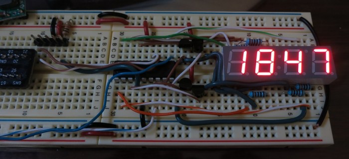


 WESTEC 2017 ran for three days, but I only got my hands on the free registration towards the end of the second day. Unfortunately that third day overlaps with
  Courtesy of Tux-Lab, I got a chance to attend
 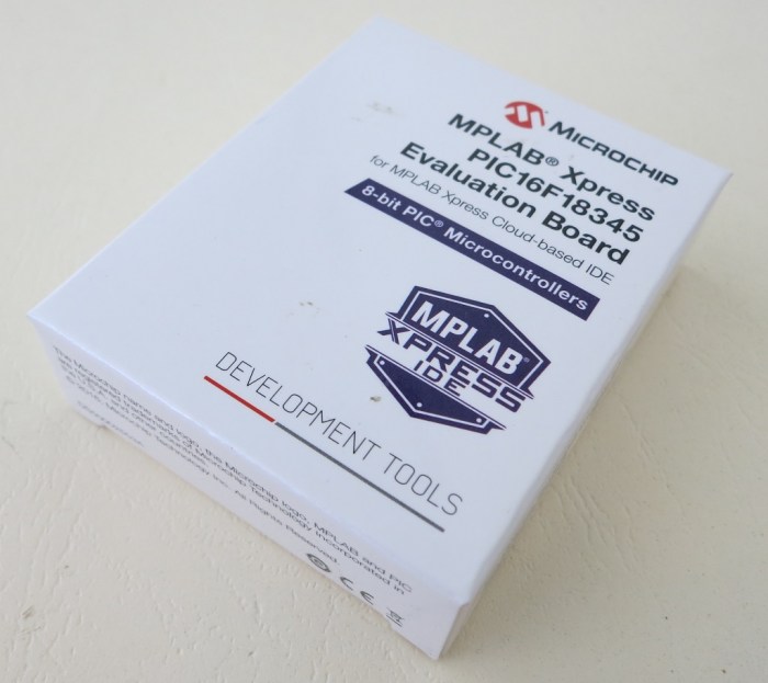 It’s been about two weeks since I started learning the
 The tutorial jumps straight into the practice with 12 simple PIC projects, each demonstrating a basic PIC task. Each project starts with how to set up hardware bits (LEDs, resistors, etc) on a project breadboard. Then it moves to the software side by walking the reader through using MCC to create all the boilerplate code setting up the project. After MCC took care of all the repetitious tasks, the reader has to add a few lines of task-specific code to finish things up.