Notes on “Get Started With The PIC16F1 Enhanced MCU Architecture”

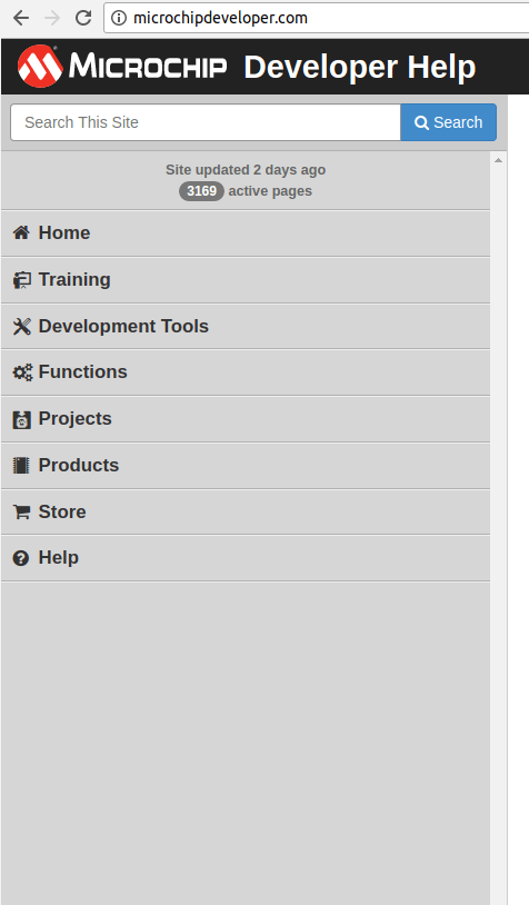
I was annoyed that Microchip didn’t make their tutorials easily accessible from their top-level site navigation bar. It took Google indexing from outside the site to point me in the right direction. Once I knew these things existed, though, it was time to get to work.

Like most of the Microchip site, the target audience is not the complete novice. This tutorial gives an overview of the features of their PIC16F1 series using vocabulary that would be understandable for people already well-versed in the field. For example, the first section explains these PIC chips are Harvard architecture designs. This was presented without explanation, footnote, or link to Wikipedia explaining what Harvard architecture was. (Hint: It has nothing to do with style of buildings on the Harvard University campus.) The target audience for this tutorial would already know what that meant.

Many years ago I dipped my toes in learning the Ubicom/Parallax SX line of micro controllers. They were competing with PIC micro controllers in some markets and share some design similarities including the Harvard architecture. At the time, I chose to experiment with the SX line because it was promoted by Parallax. Their big hit BASIC Stamp product line caters to absolute beginners and a few BASIC Stamp were created with a SX chip at its heart. Parallax offered the SX chip itself for the more advanced users. The product line was backed by documentation written by the same crew that knew how to write for novices.

Unfortunately the SX product line never found the same success PIC did. So it has since been discontinued. The little bits and pieces I still remember from the experience helps me understand PIC today. Even with that help, I’m not quite up to the level expected by the author of the Microchip PIC tutorial, which meant a lot of Google side trips to understand the various topics.

One place the SX differ significantly from PIC was the implementation intent. The SX put their focus on software: The chips were simple but designed to run at significantly higher clock speeds (75 MHz) compared to their contemporary PIC counterparts (typically 1-4 MHz). This allows the SX to implement a large range of functionality strictly in software, reducing the need for peripherals.

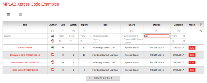
In contrast, PIC controllers – especially the ones today – is less focused on the code running on the core chip and more focus on having that code orchestrate peripherals to do the actual work. The deep product line offers PIC chips with varying set of peripherals to suit different goals. It can get bewildering but since I already have a specific PIC in hand, I can stay focused on the subset of peripherals on this PIC16F18345 chip.

Get Started PIC16

Microchip Hides Their Tutorials. Why?

The last time I tried to learn PIC programming, I was frustrated by their developer support web site. There’s a lot of detailed reference material for people who already know what they are doing and know what they are looking for. I didn’t see anything like a tutorial for novices.

This time around Google helped me find a tutorial titled “Get Started With The PIC16F1 Enhanced MCU Architecture“. Since the PIC on my evaluation board is the PIC16F18345 I thought that was a great place to start. When it came  up on my web browser, I looked on the navigation bar on the left and felt stupid. The tutorial is under the big bold “Tutorial” section on the global navigation bar. Why didn’t I see that before?

MicrochipDevTutorial
A Getting Started tutorial under the “Tutorial” section of the global navigation bar.

The answer? Because it was not there. If somebody just opens up the Microchip developer web site directly as I did before, without the URL taking me directly to a tutorial, the “Tutorial” section is absent from the navigation bar.

MicrochipDev

Most of the other sections are the same, but “Tutorial” is gone from below “Help” and instead there is “Store” above “Help”. I guess Microchip is more eager to take my money than to teach me why I might want to give them money.

Why does Microchip mask the existence of the tutorials section? I don’t know. I wish they hadn’t, because I would have been able to get started on PIC programming much earlier.

Maybe they’re ashamed of the quality of the tutorials? I hope not, because I’m about to dive in and I’d be sad if the tutorials sucked.

MPLAB Xpress Code Configurator Requires Java. Good Feeling’s Gone.

Getting started with the MPLAB Xpress development system, I’ve been impressed by what I saw. Microchip’s PIC platform has a lineage that goes all the way back to 1976 but the new web-based tools show they are making serious effort to move the development experience into 2017. A HTML-based code editor, cloud-based compilation, download to local computer, and USB storage device based hardware interface making it accessible to every modern computer with an internet connection.

I had compiled a few pre-built examples to try out the process and feeling pretty good about the whole thing. Until the time came for me to create a new project from scratch. The boilerplate code for a new project sets up all the parameters tailored to the features and peripherals of a specific PIC chip, and the tool to take care of all these details is the “MPLAB Xpress Code Configurator” (MCC).

So far so good, I clicked on the blue “MCC” icon, and got this.

MCC Requires Java

…Java?

The sound in my head is of screeching tires punctuated by the crunching metal of a car crash. Maybe they have ambition to move PIC development into 2017, but today starting a new MPLAB Xpress project requires a trip back to 1995 when Java was king.

If MCC was a web-browser based Java applet, we would be completely out of luck as Firefox and Chrome both dropped support due to all the security nightmares the past few years, and those were the only two browsers I have installed on my Ubuntu development system.

Fortunately MCC is a client-side application launched with a JNLP file so there is still some hope. I tried the open-source Java implementation first, but icedtea-netx does not work at the moment. So off to Oracle I go to download the official closed-source binaries which got me past this blocker.

In hindsight I should have created a virtual machine (probably with VirtualBox) and installed Java only in that VM to contain any possible damage from future Java security vulnerabilities. I’ll do that on my next clean install of Ubuntu.

Back to MCC: it feels like a chunk of legacy code carried over to today’s MPLAB Xpress. Having to install Java is very much counter to their “nothing to setup or install” pitch so I expect they will migrate MCC functionality to be HTML-based as well.

Hopefully it’ll just be a matter of time.

MPLAB Xpress Examples Are More Helpful When I Actually Click On Link To Explanation.

PIC processors have been a popular tool for decades, catering to a wide range of usage scenarios. If you add up all the possible features and all the possible variants, it totally overwhelms the beginner trying to find a place to start. That was my problem last time: I didn’t know which chip I should start with, what tools to learn, and I didn’t even know how to navigate the documentation to inform these decisions.

But now that I have an evaluation board, I can focus on starting off with the chip on it (PIC16F18345) and use the tool (MPLAB Xpress web IDE) it is designed to work with. Microchip provides examples to help get people up to speed. This code repository is also open for people to upload and share. As of this writing, the examples total about 200, far short of something like Github. But it’s a start.

They even have a few examples for the specific board I have. Not just the chip, the full evaluation board. This spares me the headache of trying to translate code meant for a different device. I saw the big red “IDE” on the right hand side and clicked it.

Examples 345
Big red “IDE” on right are links. Big red titles on left are also links.

As expected, the project opened up in the development environment and…

Um…

Now what?

A lot of the code in the project appear to be auto-generated boilerplate. Most of the comments are legal disclaimers and the rest are gibberish to a beginner. The main() function has a while(1) infinite loop and no code inside that loop. What’s actually doing anything here? I wandered aimlessly looking for something to grab onto as my Rosetta Stone to get started.

Jumping straight into the code was not as  helpful as I had hoped.

After a while, I had to take a break and take care of other things. When I returned, my session had timed out and I had to restart. I retraced my steps and was just about to click on the big red “IDE” when I noticed… hey. The title on the left is also big and red. Could it be a link?

Not only was it a link, it was in fact a link to an explanation of the project and steps walking through how to re-create the example from scratch. I just got distracted by the big red “IDE” taking me on the wrong path.

Hardware Support for Web-Based PIC Microcontroller Development

MPLab Xpress IDE LogoNormally, micro controller programs are written on a PC and compiled into binary code that is loaded onto the chip via a device generically called “programmer“. Afterwards, the chip can be removed from the programmer device and start performing the tasks described in the binary code.

These programmer devices are hardware peripherals. So as a web-based tool, MPLAB Xpress would not be able to utilize them without installing additional software to bridge the gap. This is counter to the “Xpress” goal of offering zero-install, low barrier to entry into the world of PIC.

Microchip Technology’s solution to this challenge is to create “MPLAB Xpress” branded evaluation boards with programmer hardware already on board. This specific product line is designed to eliminate the need for specialized devices or driver software, because it talks to the connected computer as a USB flash storage device. As far as the PC knows, this evaluation board is just another USB flash drive, which the PC knows how to access it without special drivers.

Customers with these evaluation boards could write a PIC program in their web browser with MPLAB Xpress and build the program into a binary file that the browser downloads. The downloaded file can then be copied to the evaluation board just like copying to a USB flash drive. Then the user presses the reset button on the board and the PIC16F18345 starts running the program.

An interesting side note: how did Microchip implement a PIC programmer that accepts compiled binary code via USB flash storage? They did it with another PIC. The evaluation board has two PIC chips on board: One is a PIC16F1454 always running the USB storage and programming functions. The other is the PIC16F18345 chip we’re actually writing code for.

So this is why the name of the cloud-based tool is in the name of this piece of hardware. This line of evaluation boards have been specifically designed to support the cloud-based tool, making it possible to get started writing code for PIC chips without installing any software.

Parsing the Long Name: “Microchip MPLAB Xpress PIC16F18345 Evaluation Board”

highres_464164287
Giveaway winner holding the prize in front of his Luggable PC, photo by [Shulie]
There was a giveaway at the Hackaday LA August meetup and I came home with a little box labelled “Microchip MPLAB Xpress PIC16F18345 Evaluation Board“. (Retail value: $12) While I had some vague ideas about PIC chips, I’ve never had the chance to sit down and play with one. Thanks to Hackaday LA, I now have my chance.

In my exploration of hardware projects, there have been occasional times when I thought: “Hmm, I wonder if this is the kind of problem I could solve with a PIC.” Now that I have one to learn with, I hope to reach a point where I can definitively recognize problems that I can (or can’t) solve with a PIC.

The first thing to figure out is what I actually have in my possession. The long name was more than a little intimidating but a little research parsed the name into the following components:

  • Microchip in this context is not the generic meaning but the proper name of the company Microchip Technology.
  • MPLAB is a product line of software tools they produce. Offered to engineers for developing products around their hardware such as the PIC chips.
    • MPLAB Xpress is a specific product in this line. It is a cloud-based variant of the full MPLAB software suite, scaled down to lower the barrier of entry into the world of PIC programming.
  • PIC16F18345 is a cryptic alphanumeric string but that also makes it the least ambiguous one to understand. It designates a specific chip from the extensive PIC product line.
  • Evaluation means this is for prototyping and not for companies to put into large volume products. I won’t understand why until later.
  • Board means all of the above are mounted on a single circuit board.

After decoding the individual words, my question was “Why is the name of their MPLAB Xpress software on this hardware device?”

The short answer: this evaluation board’s on-board programmer has been tailored to support MPLAB Xpress’ cloud-based microcontroller development model.

The longer answer is coming up as tomorrow’s post.


Tired PCI-Express Extension Cable Caused System Instability

I was ready for a break from working on the Luggable PC Mark II project and wanted to enjoy the results of my labor for a while. I started learning PIC programming but was frustrated by an unstable computer.

Revision A proved that the system works, and all components can happily run together reliably for a few weeks. But revision B was a problem child. It started off with occasional temporary recoverable system freezes. Then the system freezes would not recover and I had to power cycle the computer. Degrading further, the unpredictable failures would spontaneously reboot the computer.

The unpredictable nature of these events makes diagnosis difficult. Sometimes many hours would pass before an event, sometimes they would happen twice within the same minute. When one variable is changed, the system has to be left running to test if the change helped. Sometimes this meant running a system for hours before another reset occurred.

My initial suspicion was on overheating because a tremendous heat wave hit Los Angeles this week. But there was little correlation between temperature and stability. One of the “reboot itself multiple times within a minute” events occurred during the cool night.

The next suspicion was on power, as an under-voltage could cause these symptoms and the heat wave means a lot of air conditioners running in the neighborhood. But reboots continued after swapping in a different power supply and putting the system on an UPS.

The key insight was a system freeze during a work session where I had music playing in the background. The music continued but the screen is frozen, implying the video subsystem.

The PCI-Express extension cable was an unknown. I explicitly excluded one from Luggable Mark I just to eliminate that variable. As a test, the video card is inserted directly into the motherboard. The system is not luggable at all in this state but it proved informative because the system stayed stable for 24 hours.

Looking at the cable I removed from the system, I can see a lot of wrinkles from all the times I experimented with the layout and changed relative dimension of the components. Hypothesis: metal fatigue has started cracking some of the wires in this ribbon cable causing intermittent connections and general system chaos.


Wrinkly Cable

Normally a system installer would bend the ribbon cable into place once and leave it. I consider my usage pattern of performing many different bends over many weeks beyond normal expectation. Like bending a paperclip back and forth until it breaks.

In short: “My bad”.

I ordered another cable from the same vendor off Amazon (*), installed the replacement, and that restored system reliability. I plan to leave this second cable alone as much as possible. When I start working on revision C, I will use the old cable (now labelled “TEST”) to try out different layout ideas. Bend and flex and twist as I experiment. I won’t change the bends on the new cable until I settle on a layout.


(*) Disclosure: As an Amazon Associate I earn from qualifying purchases.

Rev. B @ Hackaday LA August Meetup

There’s nothing like a deadline to drive progress, so I’ve imposed deadlines on myself to keep things moving. For Luggable PC Mark II Revision B, the self-imposed deadline was to get it finished (enough) to show at the Hackaday LA August Meetup. It was a mad scramble towards the end, cutting fancy feature ideas in favor of simple ones that can be done quickly within the deadline. But I made it! I took it on the Metro Gold Line train to the meetup venue SupplyFrame DesignLab. Here’s a picture somebody took of rev B sitting on the projects show-and-tell table.

highres_464139891

Luggable PC Mark II Revision B sitting on the projects show-and-tell table along with project from other people. I’m not visible in this picture by [SpencerSkelly]

I always forget to take pictures of my own project while at a Hackaday meetup… I’m too excited talking about my project. I’m not visible in this picture. The location I spent most of my chatting time is blocked by the person with white polo shirt on the right.

Many Hackaday LA regulars are familiar with my Luggable PC Mark I, and might even be getting tired of it. Mark II was a fresh take and attracted a new wave of attention. It is always fun to share my projects with like-minded people.

RevB_Backjpg

RevB_Front

A downside of mad scrambles to meet deadlines is overdose. I’m enthusiastic about Mark II and there’s still lots to problems I need to fix with rev B…. but after the deadline scramble I’m ready for a break before I start working on rev C.

I was planning to go back to learning Python, but they had a giveaway at this meetup and I was granted a Microchip MPLAB Xpress PIC16F18345 Evaluation Board. Getting some basic familiarity with these low-power (in both computation power and electrical power) microcontrollers had been on my to-do list for some time. Now that a PIC microcontroller board has dropped in my lap, I might as well run with it!

Make a Flexible Bracket With 3D Printing Vase Mode

Due to real-world inconveniences like gravity and manufacturing tolerance, the monitor sags relative to the aluminum extrusion frame of Luggable PC Mark II Revision B. We’ll have to compensate for this by adding something to help hold the monitor in the frame.

This Lenovo L24q-20 has barely any bezel around the screen, which was a tremendous plus when I was shopping around monitors. The tiny bezel makes for compact dimensions which makes it easy to package, and the lack of excess material contributes to weight. But now the lack of bezel means I need to be careful with the bracket that we’ll need.

When there’s physical stress on a LCD screen, it distorts the layers inside and show up as visible color distortions on-screen. It isn’t good for the screen and doesn’t look good, either. We want something that can spread this stress evenly over a large area. Ideally something flexible so high-stress areas can give way to balance the load.


I started designing rigid 3D printed brackets with stick-on foam strips for flexibility, but then remembered “vase mode”. This is an option in 3D printing where, instead of printing a solid object, the plastic is only extruded on the perimeter. This results in a thin shell of the shape, the thickness of the wall is the 3D printer extruder nozzle diameter, and the center is empty.

Thingiverse had a few objects to be printed in “vase mode”. It was good for showing off something 3D printers can do easily that is difficult for other manufacturing methods. But while it was good for these Thingiverse trinkets, I didn’t see a functional use for this technique… until today!

I designed the shape I wanted in Fusion 360 (as a solid) and printed a short segment using vase mode to prove the idea is sound.

Monitor top test clip
Short test piece of clip printed with vase mode

Once the short test piece proved successful, I proceeded to print enough segments to cover all available space on the extrusion bar. (Everything not taken up by the handle or the corner pieces.) They hold the monitor in place while distributing that pressure across almost the full width of the monitor.

Clip full width
Four segments of flexible clip (two on each side of handle) printed with vase mode

CAD World vs. Real World: Chassis Flex

On today’s episode of “why we build prototypes”: chassis flex.

In the digital CAD world, all features are exactly as drawn. Their dimensions always perfectly match the specified value. All surfaces mate perfectly. All fasteners are aligned to their holes. All dimensional values are static and never change, regardless of the physical stresses applied on them. Multiple objects are allowed to occupy the same space.

None of these things are true in the real world.

Digitally simulating all the messiness of the real world are hard. There exists software tools for engineers to simulate specific aspects. Interference checking can try to find objects occupying the same space, but it can be deceptive because they rarely take into account all the other factors such as manufacturing tolerance and physical stresses.

Finite element analysis can help understand how objects move in response to physical loads in the real world. It takes some level of expertise to properly set up an analysis, beefy computing resources to run the simulation, and then human expertise again to interpret the results. A badly set up simulation will tell the wrong story, a bad interpretation can do the same, and manufacturing tolerances can throw everything off in unexpected ways.

For a hobbyist project that is quick to build and failure is cheap, it is faster and easier to find out how things act in the real world by just building it in the real world. Hence the construction of Luggable PC Mark II Revision B. Seeing everything in the physical world highlighted some problems. Most of them are trivial, but one stood out.

The Lenovo monitor is attached in the lower back, using a metal plate I pulled from the original display stand. The plate goes to a 3D-printed spacer, which attached to aluminum extrusion bars, which attach to another 3D printed part, before it is attached to the bottom of the aluminum frame. All those less-than-perfect joints add up to a clearly visible problem. The monitor is supposed to sit within the aluminum extrusion frame, but when all the little errors accumulated, the top edge of the monitor does not sit in the frame like it did in CAD, it actually juts out over 20 mm from the frame.

Next: how to help the top of the frame and the top of the monitor stay together.


Screen frame separation