Fusion 360 Scripting: Learning Resources Overview

fusion-360-logo31I don’t know how much Autodesk expects their Fusion 360 users to write their own custom scripts, but Autodesk have certainly made enough information available free online for anybody to give it a try. Broadly, they are divided into three categories:

  1. Why“: the Fusion 360 API User’s Manual describes the overall concepts of how the API is designed and laid out. It is written to be the starting point before the programmer dives into actual code.
  2. What“: the Fusion 360 API Reference Manual documents the specific nuts and bolts of how a script communicates with Fusion 360. This is where developers go to find the small but important details necessary to write good Fusion 360 code.
  3. How“: Autodesk provides sample code so we can see some already-written scripts and get a feel of how they work. Some people may prefer to start with the code before (or possibly ‘instead of’) going to the concepts described in the user’s manual. But every learner will need to cross-reference the sample code against the reference manual to understand everything a sample does.

I appreciated the foundation laid out by the user’s manual. It left me feeling confident that I could march into the scripts and be properly oriented to understand what I’m seeing and how to find answers when I need them. Whether this confidence is misplaced or not is too early to tell at the moment.

One thing that I found interesting: Autodesk provides sample code of different styles across multiple venues. There’s a fairly large set of samples alongside the manuals on Autodesk’s own help website, but there is in addition a Github account “AutodeskFusion360” where script code is published. Some are samples, some are hackathon projects, and some are scripts that they’re released to solve some problems that customers have raised in the forums.

Together they cover a pretty wide spectrum of code to learn from, from simplified educational code snippets to complete scripts intended to run on user workstations.

Windows Subsystem Returns for Linux

One of the newest features in Windows 10 is the “Windows Subsystem for Linux” (WSL) allowing a limited set of Linux binaries to run on the latest 64-bit edition of Windows 10. It may be a sign of open-source friendliness by the new Microsoft CEO but for trivia’s sake: it is not a new concept.

The lineage for Windows 10 traces all the way back to Windows NT, built-in the early 1990s as a heavier-duty operating system (or according to some, “a real operating system”) to move upscale relative to the existing DOS-based Windows (“not a real operating system”). As consumer-level hardware grew more capable, the old DOS core was phased out and the NT kernel took over. Windows 2000 was the modest start, followed by the successful Windows XP.

But back when Windows NT launched, it was intended to capture the business, enterprise, and government markets with higher margins than the consumer market. At the time, one requirement to compete for government contracts was support for POSIX, a IEEE-defined subset of Unix. The software architects for Windows NT built a modular design that supported multiple subsystems. In addition to the home-grown Microsoft Win32 and the POSIX subsystem to meet government requirement, there is also a subsystem for IBM OS/2 to compete in enterprises that had invested in OS/2.

History showed those subsystem were barely, if anything, more than lip service. They were not used much and gradually faded away in later evolution of the NT lineage.

But now, the concept returns.

Microsoft has a healthy and profitable market in desktop software development with Windows, but is only a marginal player in the web + cloud world. The people writing code there are more likely to be using a Linux workstation or a Macintosh with its FreeBSD-based MacOS. In an attempt to make Windows more relevant to this world, they need to provide access to the already entrenched tools.

So just like before, Microsoft is building a Linux subsystem for business competitive reasons. But unlike the POSIX subsystem, they couldn’t get away with just lip service to satisfy a checklist. It will actually need to be useful to gain meaningful traction.

The method of installation is a little odd – the supported Linux distributions are listed on the Microsoft Windows app store. But once we get past this square peg jammed in a round hole, it works well enough.

WSL is not a virtual machine or even a container. The Linux executables were not recompiled for Windows, they’re the exact same binaries. And they’re not isolated – they run side by side with the rest of Windows and has access to the same file system.

Personally, I’m using WSL so I can use the same git source control commands that I’ve learned while working in Ubuntu. I know Github has a Windows GUI and associated command-line toolkit, but I expect running the Ubuntu git via WSL would work better with git outside of Github. (Bitbucket, Heroku, etc.)

This is a good start. I hope WSL has a real life ahead to help Windows play well with others, and not fade away like its predecessors.

Dell Latitude X1: A 2005 Laptop Tries To Fit In 2017

I thought it might be fun to try to get the twelve-year-old Dell Latitude X1 laptop up and running. My expectations were not high, but when I looked over the hardware specs I found the out-of-date hardware surprisingly within reason to run current software.

The computer came with Windows XP, which is long out of service. The previous owner of this laptop switched to running Ubuntu 11. Since that’s far out of date as well and I had no login information anyway, a clean wipe is in order.

I thought I’d jump straight to the latest Ubuntu 17.10, but was unable to find a 32-bit installer. The lack of a 32-bit installer turns out to be an intentional omission, part of Ubuntu’s plans to phase out 32-bit support. So I installed an older version (16.04 LTS) which did have a 32-bit installer, and upgraded from there. The resulting system was quite sluggish. After using it a bit, I decided part of the problem was the spinning-platter hard drive but there’s also the old graphics chip struggling to handle the visual effects of a modern OS.

To isolate the latter, I installed Ubuntu MATE, a variant of Ubuntu with the MATE desktop. MATE is a simpler alternative which is supposed to run better on lower-end hardware. That part was true – after installing Ubuntu MATE, the Latitude X1 didn’t spend as much chugging through graphical transitions. But the overall experience was still slow – the spinning platter hard drive remains a significant influence on performance.

Switching to MATE would have made a larger difference if I had a larger screen (or multiple monitors) running multiple windows. But since the Latitude X1 screen was so small, I only have one window at a time running full-screen, reducing the influence of the desktop environment.

The Latitude X1’s performance on modern software is held back by the spinning-platter hard drive. Which led to the next idea: can we upgrade the hard drive to a SSD? I have a few old SSDs available for such a project.

Dell always publishes excellent manuals for working with their machines. They also keep them online and available, even for twelve-year old machines. So getting to the hard drive was no problem. As soon as the hard drive was visible, though, I knew I was in trouble. The drive is much smaller than the standard laptop hard drive.

HDD18HDD35

Even if the SSD could physically fit, it did not have the correct data interface. The interface connector is unlike anything I’ve seen in a laptop hard drive. The closest thing I can recall is a CompactFlash connector.

HDD18Plug

The label on the drive proclaims itself to be a Toshiba MK3006GAL. Sadly, unlike Dell, Toshiba does not keep documentation online for old hardware. I remain ignorant of the details and industry specification for this specific hard drive interface and form factor. Maybe it is rare enough that there would be no SSD upgrade possible at all. Since I was not planning to spend money on this project, though, the details are irrelevant. This old computer will stick with its old spinning platter hard drive.


If I had to make a prediction 12 years ago about how well the Latitude X1 would hold up to the years, I probably would have predicted the CPU speed as the largest bottleneck, followed by the quantity of RAM. I would not have guessed that the growth of cheap tablets would demand that operating systems continue to run on a 1 gigahertz processor and within 1 gigabyte of RAM.

I also would not have guessed that solid state drives would have dropped in price and become such a cost-effective boost to overall system performance. The hard drive turned out to be the most significant sign of age in this twelve-year-old laptop.

Dell Latitude X1 is Almost a Teenager

Today’s new toy is actually an old toy: a Dell Latitude X1 ultra-portable laptop that was originally released in early 2005. The fact that it is still running twelve years later is fairly impressive. I was once skeptical of the price premium Dell charged over their consumer product line, but I’ve seen enough consumer Dell die off while their business Dell counterparts kept trucking to change my mind. While I still might not choose to pay that premium, I now believe the price difference buys a more durable product.

Or perhaps the credit should go to Samsung? When I searched for reviews of this old laptop, I found this review which claimed the laptop is a rebadged Samsung Q30. The article even helpfully included a picture of the Q30 so we can see cosmetic similarities (and the differences.)

There are dings and dents from over a decade of service, but aside from the expected degradation in battery capacity, the machine seems to be running much as it did over a decade ago. I booted it up to verify that it could still do so (Looks like the previous owner installed Ubuntu 11) before I started digging into the hardware.

Looking into the BIOS, I find the processor is an Intel Pentium M ULV 733, a 32-bit single-core low-power processor running at a modest 1.1 GHz. It is definitely out of date in the current age of 64-bit multi-core multi-gigahertz CPUs but we might still be able to work with it.

There is 1.2 gigabytes of RAM, an unusual amount that I’m sure it was quite a luxurious amount in its day. Not so much today, but not as bad as it could have been. In the days of Windows Vista there was an expectation that computer memory baseline would keep moving up, 2 then 4 then 8 gigabytes and beyond, but it hasn’t panned out that way. Demand emerged to run on lower-end hardware so recent builds of Linux and Windows 10 both included provisions to run on inexpensive tablets with 1 gigabyte or less of RAM.

The same break in the capacity trend also applied to storage. This machine has only a 30 gigabyte hard drive, and hard drive capacity have grown to multiple terabytes within the past decade. But the advent of solid-state storage plus the desire for inexpensive tablets with modest storage meant operating systems had to stay slim.

All the remaining accessories follow the same trend – definitely out of date but surprisingly still within the realm of relevance. A screen with resolution of 1280×768, Bluetooth and Wi-Fi, Ethernet and USB, SD card reader, all the trappings expected of a modern laptop.

There are a few amusing anachronisms: a CompactFlash reader in addition to the SD reader. There is no HDMI video out port – just VGA. And the best one of all – a telephone jack for dial-up modem connectivity.

LatitudeX1Modem


Overview: Fusion 360 vs. Onshape Scripting

My fascination with gears led me to the scripting mechanism in both Fusion 360 and Onshape. Both CAD packages offer only minimal gear generation capabilities, and not even built-in to the main software: Spur gear generation was given in the form of an external add-in. This meant they are ideal introductory entry points to examine the different design philosophies.

The Onshape team invented their own scripting language called FeatureScript. It has some superficial similarities with C-style languages which helps a software developer get up and running more quickly on the new language. The code libraries are designed specifically around designing parts within a Onshape feature studio.

In contrast, Autodesk did not try to invent a new language. Instead, they decided to support multiple existing languages and let the user choose the one that best suits their purpose. C++ or Python. (Fusion 360 used to also support JavaScript, but support has been deprecated.)

Readability: Because FeatureScript was designed specifically for its task, the code is much more direct and readable. All API are designed to fit with FeatureScript because that’s the only language supported. Fusion 360 C++/Python code must call into the Autodesk library code which had to be adapted to be usable across languages. Advantage: Onshape.

Performance: C++ can be compiled to native code and executed on the local computer. For small tasks, this will be the fastest possible option. Python code running locally wouldn’t be quite as fast, but unlike FeatureScript, it does not have to deal with network latency. Advantage: Fusion 360

Security: FeatureScript executes in a secure sandbox on Onshape server, and thus limited in risk for exploitation by bad actors. In contrast, a native C++ binary can easily host hostile code. Python is slightly better in this regard, but it’s not clear how much effort (if any) Fusion 360 puts into running Python securely. Advantage: Onshape

Development: Like the rest of Onshape, all work with FeatureScript takes place within the user’s web browser window. If the developer does not like the Onshape FeatureScript editor, they are unfortunately stuck. In contrast, Fusion 360 presents many options. C++ development takes place on a platform-appropriate IDE (Visual Studio for Windows, Xcode for MacOS) and for Python the Spyder IDE is provided. Advantage: Fusion 360

Evolution: FeatureScript is owned by Onshape and any future evolution is fully under Onshape control. Since all FeatureScript written by users are stored on Onshape servers, they can validate any future changes for compatibility. In contrast, Autodesk owns neither C++ nor Python and could not direct future evolution. And since Autodesk does not host the plug-in code, they have no visibility on breaks in compatibility. Lastly, as history has shown, Autodesk can choose to abandon a language (JavaScript) and all the users on it. Advantage: Onshape

Capability: FeatureScript is constrained to feature creation in a parts studio. Autodesk API is currently roughly similar, focused on the model designer portion of Fusion 360, but they are starting to branch out. As of this writing they’ve just started rolling out some basic scripting capabilities for the CAM module and stated intention to do more. Advantage: Fusion 360


Python LogoFor the immediate future, I intend to focus on Fusion 360 scripting via Python. I’ve wanted to become more proficient in Python, and this would be a good way to look at Python through a lens entirely different from writing Qt code on a Raspberry Pi. I also have ambition to write Fusion 360 plug-in that leverages external libraries to provide novel services, and that’s not possible when stuck inside the FeatureScript sandbox. I will just have to keep a careful eye on the Python library imports in an effort to keep the security risks under control.


Fusion 360 and Onshape: Spur Gears via Scripts

I’ve been learning Onshape and Fusion 360 as they are two of the cloud-based CAD solutions with a subscription tier that’s free for me. They each have their strengths and weaknesses and it’s always interesting to compare and contrast between them.

One item they share that I found surprising is that neither of them has built-in capability to add gears into the mechanical design. I’ve always thought of gears as a critical part of any nontrivial machinery. So I had expected to find a significant section of the CAD package to be devoted to creating various types of gears for different applications, simulating and analyzing their suitability to the task, but there was nothing.

For basic projects, a simple spur gear would suffice. Thankfully, both companies have heard the user requests and made simple spur gear creation available as an add-in created with their own respective scripting mechanism.

Extending Onshape requires learning to write code in their custom language FeatureScript. A member of the Onshape team used it to create the spur gear script and made it available in the public documents library. One downside of this approach is the fact that (1) Onshape users needs to make a copy of a public document before they could use it for their own purposes, and (2) all documents created with the free subscription tier of Onshape are public. These two factors combined means many, many copies of the spur gear script in the public documents library. Correction: Custom FeatureScript can be added to the toolbar without making a copy. Thanks [FS] for the comment!

OnShape Spur Gear

Fusion 360 did not declare their own scripting language. They expose their extension API to two languages: C++ for the high-performance native code crowd, and the Python interpreted scripting language for the less performance-focused audience. They used to also support JavaScript, but as of July 2017 they have moved that into maintenance mode due to lack of usage.

The spur gear script is part of the sample script library installed alongside Fusion 360, so I didn’t have to find a separate download nor was copying of public document necessary. They presented it in both C++ and Python format. I found the Python version in the “Scripts and Add-ins” menu and clicked “Run”.

F360 Script Addin

Onshape and Fusion 360’s spur gear scripts present their gear parameters in slightly different formats, but both should suffice for simple projects. If I want to do something more complex, I will have to dive into coding my own extension script.

I’ve wanted to learn more about what is and isn’t possible in an extension script anyway, so… challenge accepted!

F360 Spur Gear


Waiting For Efficient Voice Control

When I started playing with computers, audio output was primitive and there were no means of audio input at all. Voice controlled computers were pure science fiction. When the Sound Blaster gave my computer a voice, it also enabled primitive voice recognition. The mechanics were primitive and the recognition poor, but the promise was there.

Voice recognition capabilities have improved in the years since. Phone-operated systems have enabled voice controlled menus within in the past decade or so. (“For balance and payment information, press or say 4.”) It is now considered easy to recognize words in a specific domain.

Just within the past few years, advances in neural networks (“deep learning”) have enabled tremendous leaps in recognition accuracy. No longer constrained to differentiating numbers, like navigating a voice menu, the voice commands can be general enough to be interesting. And so now we have digital assistants like Apple’s Siri, Google’s Assistant, Amazon’s Alexa, and Microsoft’s Cortana.

But when I tried to communicate with them, I still feel frustrated by the experience. The problems are rarely technological now – the recognition rate is pretty good. But there was something else. I had been phrasing it as “low-bandwidth communication” but I just read an article from Wired that offers a much better explanation: These voice-controlled robots are designed to be chatty.

Chatty Bots
Link to “Stop the Chitchat” article on Wired

The problem has moved from one of technical implementation (“how do we recognize words”) to one of user experience (“how do we react to words we recognize”) and I do not appreciate the current state of the art at all. The article lays out reasons why designers choose to do this: To make the audio assistants less intimidating to people new to the technology, make them sound like a polite butler instead of an efficient computer. I understand the reason, but I’m eager for the industry to move past this introductory phase. Or at least start offering a “power user” mode.

After all, when I perform a Google search, I don’t type in the query like I would to a person. I don’t type “Hey I’d like to read about neural networks, could you bring up the Wikipedia article, please?” No, I type in “wikipedia neural network

Voice interaction with a computer should be just as terse and efficient, but we’re not there yet. Even worse, we’re intentionally not there due to user experience design intent, and that just makes me grind my teeth.

Today, if I wanted a voice-controlled light, I have to say something like “Alexa, turn on the hallway lights.

I look forward to the day when I can call out:

AZIZ! LIGHT!


LA Times Writer’s Take on 3-D Printing

As a Los Angeles Times subscriber, I generally appreciate their coverage of technology. I may not always agree with the accuracy or their assessments, but I appreciate their effort to make technological topics accessible for non-techies. A few months ago they ran an article on 3D printing. The writer borrowed a MakerBot Replicator for six weeks and wrote about their experience.

LA Times 3D Printer
Follow the link for the full article.

Most technology articles tend to be printed as part of the Business section. This article ran in the Home & Garden section because the writer was evaluating a 3D printer in the role of a home appliance. As soon as I realized this, I said to myself “oh no” and my expectation for the article went downhill.

Over the course of this six-week experiment, the author downloaded progressively more complex and ambitious designs off Thingiverse and printed them. The author then wrote about the experience of printing and the (lack of) usefulness of the results. The author was less than impressed by the current state of the art in 3D printing. One sentence from the conclusion: “I merely toyed with the machine for its novelty without finding a conclusive use for it.”

Reading through this, the voice inside my head was screaming: “You’re doing it wrong!” The author never explored printing their own creation. Something new and novel just for themselves. This is, in my view, the most important point of 3D printing and this article’s missed it entirely.

Here’s an analogy with a 2D paper printer commonplace in homes and offices: A writer borrows a laser printer for a few weeks, goes on the internet to download progressively longer PDFs of books written by other people. The writer never explores the freedom of printing books of their own writing. After printing a few books written by others, the author concludes there’s no reason to have a printer at home when it’s cheaper and faster to just buy already-printed books.

I can understand how this article went off on the wrong track due to the flawed premise, but I still disagree with it.

Button Cell Joule Thief on a Clothespin

Since the time I got up and running building my own joule thief devices, I’ve been having fun lighting up LED with batteries that have otherwise been given up for dead. Most of them were AA and a few AAA, but I also had a few button cell batteries sitting around that might be good for a bit of LED fun.

Since these tiny little batteries are already weak, I did not expect very long run time out of them. And these cells on hand were in several different form factors. Given these two factors, it didn’t make sense to 3D print a battery case as I had done with with the AA batteries – the effort wouldn’t be worth the result. I just needed something to hold the contacts against the terminals of these thin batteries for long enough to drain their remaining power into some LED amusement.

Initially I tried the things that were already on my desk – paperclip and binder clip – but their naturally conductive nature meant it’s hard to avoid accidentally shorting the battery. I continued thinking along these lines during household chores, and I found my answer while doing laundry: clothespins!

Since these are made of cheap injection-molded plastic, they are not conductive like paperclips and binder clips. The cheap plastic can be easily melted with a soldering iron tip to mold around parts I wanted to mount. There is a spring to hold things tight, and the jaws open up wide enough for button cell batteries.

The bulk of the circuit was melted onto one jaw, and a wire is melted onto the other jaw. I had originally intended to run the wire through the middle of the spring, and started contemplating the best way to do so while minimizing the amount of stress metal fatigue would place on the wire.

Then I smacked myself on the forehead for overlooking the obvious: the spring is itself conductive! I don’t need to worry about metal fatigue of the wire if I recruit the spring into my circuit. So that was the final step – the wires of each jaw run to the spring, and the spring itself completes the circuit.

Clothes Peg Joule Thief

Analog Adventure: Flyback Diode

Every once in a while I learn the real world analog behavior of electronics components that I only think about in abstract digital terms. The most recent lessons come from my exposure to electrically operated switches a.k.a. relays. This exposure came from two fronts: one is the small failed relay module that I pulled out of my 3D printer, the other are the larger industrial-strength relays that were recently installed on the Tux-Lab thermoforming machine.

In the idealized digital world, these are just switches that control the flow of a large amount of electrical power on command of a much smaller electric signal. The control signal goes on, the big power goes on. Signal off, power off.

In the real world, this is implemented with an electromagnetic coil that generates the field necessary to move a physical armature. The tricky part comes from the time when the coil is de-energized. When the control signal is cut, the magnetic field collapses and is turned back into electrical energy on the circuit. This is actually the heart of my recent analog electronics project: a “Joule Thief” is a very simple flyback converter circuit to convert low battery voltage into a higher-voltage spike that can illuminate a LED.

But when the intent of the circuit is actually to just switch something on and off with a relay, such a voltage spike is unwelcome. It may in fact damage nearby components in the circuit. This is why I learned I needed to add flyback diode to protect the circuit for controlling the relays in the thermoforming machine.

Adding this array of diodes to protect against voltage spike complicates the prototype circuit, but it is good insurance to have. Once the control circuit is finalized, we plan to have a real circuit board fabricated so we don’t have to deal with this nest of wires. Unfortunately, in the near term I expect some headaches associated with the additional complexity.

FlybackDiodes

Teardown Monoprice Maker Ultimate (Wanhao Duplicator 6) Failed Relay

This is the main 24V relay on the control board of my Monoprice Maker Ultimate 3D printer, which is a rebadged and lightly modified variant of Wanhao Duplicator 6. An earlier blog post figured out why it died. (Short summary: the printer design drove this relay beyond its rated limit of 10A @ 24V.) Today let’s look closer at how it died.

There were clear visual indication of relay failure in the form of a heat-distorted casing with a hole melted into it. There were no fasteners to release so the case had to be cut free from the base. Once the case was removed, we could see the guts of the relay.

Relay 20 - OpenLooking at the inside of the just-removed case, we can see a lot of heat damage. Black char marks the hottest areas, and discolored white marked the rest.

Relay 40 - Charred Case
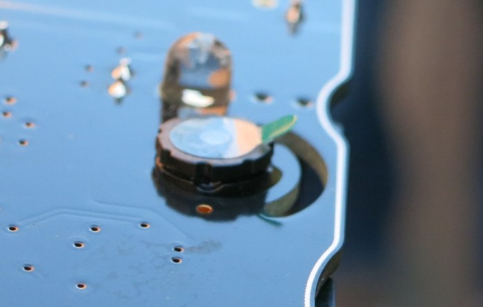
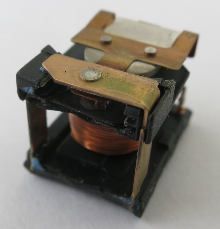
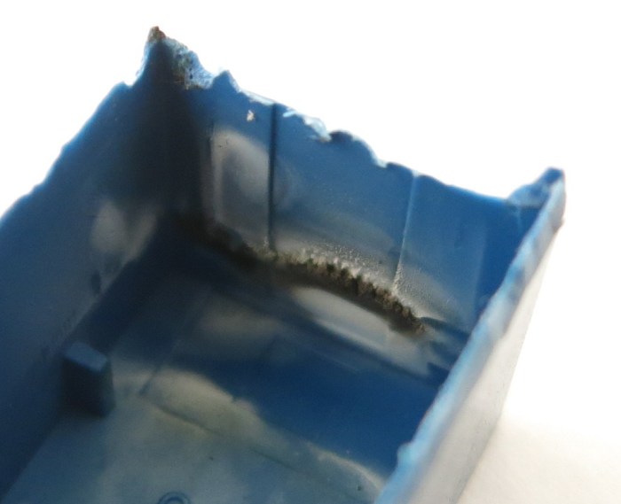
It’s a fairly straightforward relay, with the coil actuating an armature moving between contacts on either the plate above or below it. The armature+contact area is immediately behind the blacked charred bits of the case. And looking at the armature and contacts themselves, we see the relay died an unhappy death.

Relay 30 - Distorted Contact
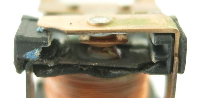
Everything in the contact area is distorted and/or charred. There is a black plastic-feeling piece holding everything in position relative to each other, and it could no longer do its job with heat distorting it and moved things out of alignment. Between the armature and the bottom contact is a blob of melted something that looks vaguely like solder. The bits of blue visible are parts of the blue casing that has melted onto this assembly. While the top contact looks OK in this picture, the side facing the armature is just as blackened and charred as the visible face of the bottom contact. The armature itself is barely visible here but it is actually discolored and distorted near the contacts.

From the Facebook user’s group, I’ve learned more recent revisions of the printer used a relay from the SRU product line to replace this SRD unit. I’m still trying to find a data sheet for the newer relay. I would hope that it is a drop-in replacement rated for at least 15A @ 24V, preferably 20A. And hopefully it would not die like this SRD-05VDC-SL-C relay did.

Disassemble Broken Garbage Disposal

A few weeks ago something under my kitchen sink started leaking water. I had hoped it was a simple plumbing failure that would be easy to fix. Perhaps a pipe has come loose or cracked a seal? Sadly this was not the case. Water was dripping off the bottom of the garbage disposal and its exterior was dry all around: Water was flowing through the interior of the garbage disposal which meant its useful service life has come to an end.

Before I dispose of the disposal, I wanted to cut it open to see exactly what failed. I guessed that a water seal has failed around the main motor shaft, and wanted to see if my guess was correct. But first, it was sent to sit in the garage and dry off.

Disposal 10 - Start
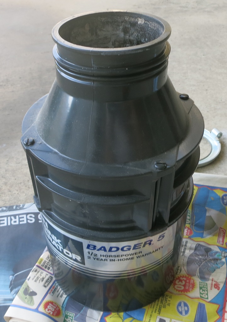
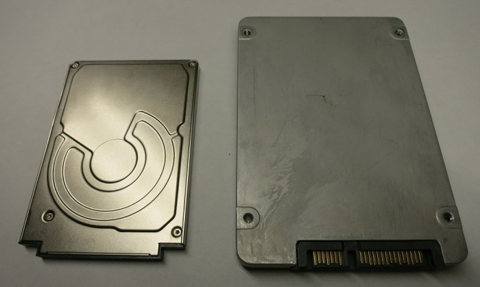
Looking around the perimeter for fasteners, the four rods immediately stood out. They are spread around the perimeter, and almost the entire height of the disposal. I tried the easy thing first but they refused to budge with my flat-head screwdriver. So out came the angle grinder with the cutting wheel, which quickly cut the exposed shaft.

Disposal 15 - Severed rod
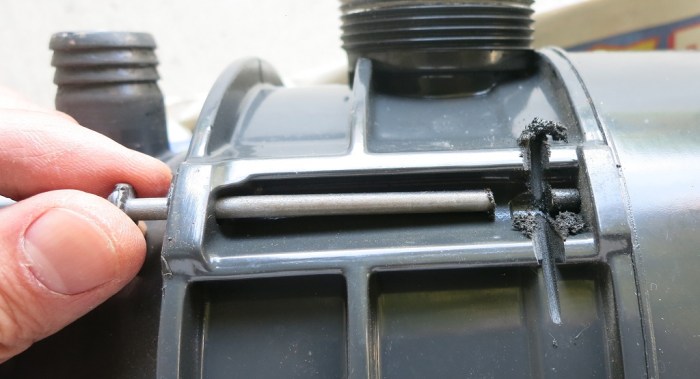
Unfortunately that did not allow the top part to come free. Something else was holding it together. Whether it is a mechanism I don’t understand or corrosion I could not tell. But there were no other obvious fasteners to release on the top side, nor is there a convenient point to start prying.

So I started looking around the bottom end of the disposal, where there was a window cut into the bottom for wiring to enter the device. That allowed me to look inside to scout out where I could best use my cutting wheel to cut the bottom free.

Disposal 20 - Bottom opened
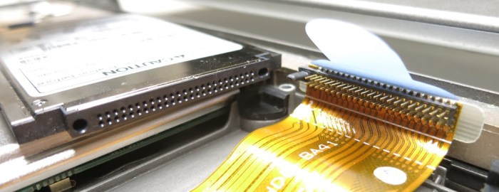
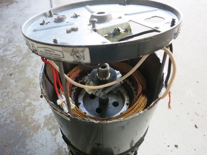
Once the bottom was cut free, I had a better view to find next best place to cut the stator free. When I pulled the stator off, I was very surprised to feel the rotor flex along with the stator because I had expected it to stay with the rest of the grinder.

Disposal 30 - Perforation
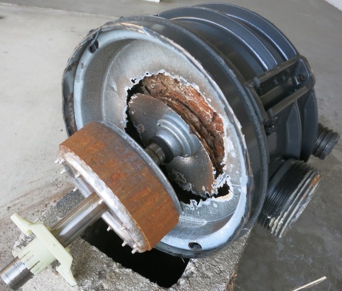
The source of the problem became clear once the stator came off: the metal plate separating the electrical motor from the grinder has been severely weakened by corrosion. I’m sure there were only a few (or maybe only one) hole when I pulled this from the sink, but the whole plate was corrosion weakened so it fell apart when I pulled the stator off the bottom.


Hologram Working to Make Cellular Data Easy

One of the sponsors at Hackaday Superconference 2017 is Hologram.io. In the attendee bag I saw a sticker with their name and logo. It was just one of many names and logo stickers in the bag so it didn’t make much of an impression beyond “I saw it”. The name “Hologram” made me think they were some sort of video or image related system, possibly VR. But when I dug deeper I found a SIM card with the company name and logo on it.

Hologram SIM

Well, now, this is different. Since video and VR are very data-intensive services, I doubt my initial guess was right. So they have something to do with the cellular network, but I had a badge to hack and thought I’d get more information later.

As it turned out, I didn’t have to go looking for more information, they came to me. Specifically two people wearing T-shirts with the Hologram logo were walking through the badge hacking area and wanted to know more about my Luggable PC. I paused my project to answer their questions and generally chat to see what people are interested in. (A big part of the fun of hanging around supercon.) I asked about their company and got the quick sales pitch: they make it easy to use cellular data.

Their SIM is just the starting point. It allows access to cellular data worldwide without having to worry about dealing with cellular carriers. Hologram takes care of that. To help curious experimenters get started, their entry-level “Developer” plan is free for the first megabyte of data in the month. Additional data would be $0.60/mb which is not the cheapest rate, but if only a few megabytes a month are needed, it should still end up cheaper than the monthly fee charged by every other carrier.

That sounds great, but they go further: Hologram Nova is a USB device that acts as a cellular data modem and can be plugged into a Raspberry Pi, or a Beaglebone, basically any computer running Linux to give it cellular data connectivity.

What if a Linux computer is overkill for the task at hand? What about projects that could be handled by something simpler like an Arduino? They’ve got that covered, too. Their Hologram Dash is a board with self-contained cellular hardware and a CPU that can be programmed with the Arduino IDE. No computer necessary.

Now I’m impressed. I’ve had project ideas that would send data over the cellular network, but they were sitting in the low-priority stack because I didn’t feel motivated enough to deal with all the overhead of using cellular data. Now I know I could pay Hologram to deal with the ugly parts and focus on my idea.

I hadn’t heard of the name before Supercon, and now I’m contemplating projects that would use their service. Their sponsorship outreach effort is a success here.

TI eZ430-Chronos and ISM Bands for RF Projects

An event like Hackaday Superconference 2017 is supported by many sponsors that want to reach that audience. An important part of the outreach is the bag of goodies handed out to conference attendees. One item was from Texas Instruments, offering a discount for the “eZ430-Chronos wireless development tool in a watch” which caught my interest.

Recent news in smart watches are dominated by Apple and Google. Very powerful but at a price point I find unacceptable. So while I’m intrigued by the idea of a wrist computer that I could write code for, I’m waiting for the market to mature and the price to drop.

ez430-chronos
Photo by Texas Instruments

It never occurred to me that there might be smart watch platforms that offer less power and capability, at a much lower price. If I had gone looking, maybe I would have found the TI Chronos watch earlier. A web search indicated it is about 7 years old so hardly cutting edge, but it is a wristwatch I could program, for around the same money as a non-programmable Casio watch from Target. The development kit also includes two USB devices: one is a programmer to deploy code to the watch, and the other lets software running on a PC to communicate with software on the watch via RF.

Following the instruction to search for “Chronos” on the store site, I got two results: eZ430-Chronos-868 and eZ430-Chronos-915. What distinguishes the -868 from the -915? I went looking for data sheets and other documentation to help me choose between them. But they all assumed the reader already knew which they’d want! It turns out this is an instance of a complete beginner tripped up by basic knowledge in the field. These numbers indicate the RF frequency the device operates on: 868 MHz vs. 915MHz.

These are frequencies of the ISM (Industrial, Scientific, Medical) radio bands, open frequency range that people can use with minimal regulatory requirements. People who have worked with ISM RF would have recognized 868 MHz as the ISM band common in Europe and 915 MHz for North America.

Well, we’re all beginners at some point. At least now I know.

Texas Instruments has a whole set of products for people who want to build RF solutions in the ISM radio band under the SimpliciTI brand. I like the fact that these hardware components are available, but I’m less thrilled with the fact the software development is based on tools by IAR Systems. I’m barely a beginner on Microchip’s MPLAB X, I really don’t want to learn another development stack right now.

I already have a set of things I want to gain proficiency on and have to choose where to spend my time. So as interesting as the TI smart watch development platform is, I’m going to have to set it aside as a distraction.

Sorry, TI!

Supercon 2017 Fun: Other People’s Projects

The Hackaday Superconference 2017 was full of people who have a long list of project ideas. And it is also a venue where it’s easy to chat people up and ask about their projects.

Here are some highlights from people I had a chance to talk to:


Yesterday’s post mentioned Ariane Nazemi’s Compaq Portable, the original luggable PC. While he is very obviously skilled at keeping old PC running, he also does some pretty cool modern stuff. The talk was about mechanical keyboards and his Dark Matter keyboard in particular.

img_6113
Photo from Atom Computer web site’s Project Dark Matter page.

I was quite encouraged to learn that making my own custom mechanical keyboards wouldn’t be as crazy as I thought they might be. I’m rather particular about the feel of my keyboards, and the encroachment of cheap membrane keyboards meant I had to pay more and more for the mechanical keyboards with the feel I like. I’m now well into the gamer keyboards of the ~$100 range. Which, according to Ari, is to the point where I might as well start building my own. I’ll give it serious consideration.


I had the chance to chat with Sarah Petkus after her talk about her robotics projects, looking at robots from a refreshingly different perspective than most robot tinkerers I’ve met. Her projects are “personally expressive”, more works of art than functional tool. But they’re not just static sculptures! The projects are still real machines built from the same mechanical principles I’m familiar with, but they were born out of very different motivation.

I have not considered robots from her world view, and it was mind-opening to try to see and think about robots in a different way.

And it was a pleasure to meet Noodle in person.

dodlt9du8aaw85x
Photo by Twitter @cameronjblocker

Sarah said Noodle doesn’t walk very well just yet, and there are a lot of challenges to solve on the way to get there. I have ambition to know about control systems for leg-walking robots, but I’m not there now. Perhaps, if I ever get there, I can help her teach Noodle to walk. (Or better yet, help Noodle learn to walk.)


I was impressed by the Tomu project: an ARM microprocessor that fits mostly in a USB port and costs roughly $10. It is in the very early stage of development and like almost all open source projects, could use the help of more people. The creator was at Supercon to spread the word. As an incentive to join in the effort, people who do something useful and submit a pull request on Github will receive a unit. I’ll look into this in more detail later.


The creator of OpenMV was walking around and showing off units and giving demos. This project is at a much more advanced stage than Tomu was. It’s a product versus a project getting off the ground. As a result the demo is less a recruitment for the effort and more of a sales pitch. Still, it looks pretty cool and I’m definitely interested in machine vision. Once I learn enough about vision to understand what OpenMV can and can’t do for me, I’ll evaluate if I’m interested in buying.

Supercon 2017 Fun: The Original Luggable PC

I named my Luggable PC project after the original IBM PC clone by Compaq. The Compaq Portable was the computer that started the PC clone market that is still going strong today. It picked up the nickname “luggable PC’ because it was roughly the size and weight of a sewing machine. I’ve seen pictures in books and on web sites, and occasionally I see a unit on display in a museum somewhere. I never expected to see and touch a running unit.

So I was pleasantly surprised (and amazed!) to see one at Hackaday Superconference 2017. It was brought in by Ariane Nazemi, who gave a talk about mechanical keyboards and brought the Compaq as one of his visual aids showing old-school mechanical keyboards. Chatting with Ari I learned one of his hobbies is to restore old computers to running condition. So the original luggable was not just a demonstration piece, it was an actual functional computer.

One of the optional equipment available for the Compaq Portable was a Computer Graphics Adapter. The CGA resolution of 320×200 is has long since been surpassed by modern equipment. But it isn’t very far off from the conference badge camera’s resolution of 128 x 128. And that’s probably why Ari worked to incorporate the Compaq into his badge project. I didn’t want to bother him while he’s focused on getting it to work, but I did ask to take a picture of my Luggable PC sitting next to the original while he worked.

LuggableOldAndNew

I had looked forward to his project presentation at the end of the conference, but I missed it because I had to take care of some administrative tasks. Alas.

It was great to have these two sit side-by-side and see over thirty years of progress in PC hardware evolution.

(Cross-posted to Hackaday.io)

Supercon 2017 Fun: Big Screen + Little Screen

I brought my Luggable PC Mark II (Rev B) to the Hackaday Superconference 2017. Its primary purpose was to be my development workstation as I dug into the source code for camera badge hacking. Its secondary purpose was to serve as conversation ice-breaker since the Supercon crowd includes the kind of people who would appreciate it. It accomplished its mission on both fronts!

One fun experience that came out of the weekend was sitting down in the badge hacking area next to the person behind the PaperBack project. He thought it was hilarious that I had the biggest screen on the table and his was the smallest. One discussion led to another and we decided it would be fun to have my computer simultaneously drive its big 24″ screen and his 6″ PaperBack screen.

We had to borrow a DVI to VGA connection from another helpful person in the badge hacking area, and there were some further fiddling with wiring connectors and display settings. (Including several reboots between Ubuntu and Windows since they each provide different ways to customize display parameters.) But eventually we got my Luggable PC to talk to his PaperBack as an external display.

PaperBack closeup

I put our respective Hackaday.io project pages on each of the displays. His PaperBack showing his project page, and my Luggable PC screen showing its own project page.

PaperBack and LugPCmkII

This was a completely random project done mostly just to see if it could be done. Exactly the kind of curious exploratory spirit that was pervasive throughout the conference.

(Cross-posted to Hackaday.io)

Supercon 2017 Badge Film “In the Back Alley”

My Superconference 2017 camera badge project concludes with the 1-minute short “In the Back Alley of Spercon.” I entered it into the short film festival and was ecstatic to have been selected as the winning film!

I recorded a bunch of footage during the day on Saturday, but once the sun went down the camera could no longer record usable footage. So I switched efforts to putting together a presentation of what I’ve recorded. Since the camera badge has no audio capabilities – no microphone nor speaker – it was going to be a silent film by necessity. I followed precedence for silent films, using the text capabilities of the camera badge app framework to put up static text which give context to the moving pictures.

I started with the ambition of writing a short film editing app on the phone, and quickly decided that would take more time than I had. I switched to hard-coding the sequence of text and videos into a single app that I could run on the camera badge. You can still see my original intent in the filename “avitrim.”

Once running, I had something I could show to other people. Friendly curious people had asked about my project in progress Friday and Saturday, and now I could press “Go” to show them the results. Unfortunately that wouldn’t work for the film festival, where they intend to put it up on the big screen. I talked to Hackaday Mike and he suggested I record the badge app in action and put it up on YouTube.

I tried a few different cameras and they all exhibited problems trying to record the footage playing on the OLED screen. Blooming, flickering, and loss of color saturation to various degrees that I struggle to correct with camera settings. The least-bad version came from my cell phone’s camera so that’s the one I uploaded to YouTube.

Playing the YouTube clip on my TV indicated the video was good enough, but the audio was not. I held my breath during the recording so people wouldn’t have to hear my breathing, but the microphone picked up other background sounds. To cover up this annoyance, I went to the YouTube royalty-free music library and picked out a music clip that’s roughly a minute long. It’s not exactly my favorite song but it’s far better than random background noises.

(The project described in this post is documented on Hackaday.io and the source code is publicly available on Github.)

Supercon 2017 Badge – Now Recording Time Lapse Video

I arrived at the Supercon badge hacking area Saturday morning and immediately got to work. I picked up where I left off – looking for the place in the code where I can change the frame playback rate to be higher than the 1fps capture rate. Once done, a test run confirmed that the automatic power-off will shut down the camera during a time-lapse so I added a line to reset the powerdowntimer counter during a time-lapse capture.

According to the plan, I should now take what I’ve learned and write a dedicated time-lapse capture app. But as I’m successfully recording time-lapse footage, the motivation to do has dropped drastically. I’d rather walk around and try to record fun footage around the conference. So with that, I’ve abandoned the previously planned “phase 2” and “phase 3”. I’m now more interested in utilizing my time-lapse video capability instead of continuing to invest time refining it. Time is an extremely limited resource on this weekend project!

The badge is not taking full advantage of the sensor, so the lack of resolution and crispness is not a surprise. But since we’re getting so little out of the sensor, we can use all the help we can get. This is why I was both excited and felt sheepish when I realized that I had been filming for half the day with the protective plastic still covering the lens. Removing it didn’t make as much of a difference as I had hoped but hey, every bit counts.

Increase Resolution

Once the sun went down, I stopped shooting footage. There is not enough low-light capability to obtain useful video. Returning to the computer, I started brainstorming the best way to present what I’ve captured. I started trying to write a rudimentary video editor (just to trim frames before and after the parts I wanted to keep) but I had no luck navigating the AVI data structure.

With the ever-ticking clock, I changed tactic: instead of an editor, I’m going to write an app that is hard-coded to play specific video files in order, and a few blocks of text in between. Just like silent films of old. I’m confident this less-ambitious application could be finished by Sunday afternoon.

(The software project discussed in this post is publicly available on Github.)

Supercon 2017 Badge – Software Orientation

With the focus on getting the panning base up and running before Supercon weekend, I haven’t spent as much time as I had wanted on software side. The camera badge source code was released a few weeks ago and were constantly getting updated as the weekend got closer. (Differences between the prototype and production boards, plus other fixes.) I had wanted to keep up to date with the software but my project investigation and the pan base took up all the time I had to spend on this project.

As soon as I had two bases up and running, I went to the early check-in and badge hacking session Friday afternoon. It started at noon and I thought showing up at 3pm would still allow some time to work. I did get some time to work, but I also found that plenty of people arrived before I did and there were no table space remaining.

IMG_5340

Oh well. At least I have the badge in hand now. The first thing I did was to perform a quick test. The camera badge came with a video record option, which I intend to dissect for my time-lapse video app. But until then, I could do a real-time video captured while panning on my base to show the basic concept works.

Another bonus of getting the badge in hand is that I was immediately more productive learning the code. The source code was informative, the documentation online was helpful, but my brain needed the anchor of actually seeing the code running. It’s was a great help to play with a menu with my hands, then go back to read the code drawing that menu. The code made a lot more sense after seeing it in action.

I dove into the basic app support framework, and after I understood the basic structure, switched to analyzing the camera app. By the end of the evening I understood enough to know how to modify the camera app to restrict the video recording frame rate to one frame per second. This artificially limited rate much more closely resembles what I would want to do in my time lapse app.

Unfortunately the playback frame rate is “accurate” in the sense it tries to play one frame per second. I have more learning ahead of me before I start writing my own time-lapse app. As a short term workaround, just to see things work with what I have, I copied the file to my computer and used ffmpeg to convert the frame rate of my end-of-evening milestone video.

(The project discussed in this blog post is publicly available on Github)