Encoder Fixed, Manual PID Tuning Begins

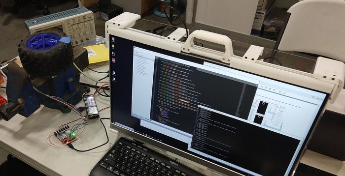
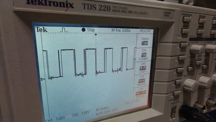
The jagged wave form of the encoder signal was diagnosed to the plastic filament used to print the encoder wheel. It was opaque to visible light but the infrared light used by the optical encoder could penetrate enough to trigger false transitions. Reprinting the encoder wheel with a different plastic resulted in clean encoder square wave form confirmed under an oscilloscope.

The planetary gear updated with the encoder is unfortunately correlated with a new problem: the automatic PID tuning algorithm in Ion Studio stopped working. Whenever the tune button was pressed, a few motor movements would occur in the first half second or so, then the software freezes up. Status LED on Roboclaw stopped blinking, confirming that communication between the software and the control board broke down. The motor continued spinning according to the last instruction it received. Terminating Ion Studio was not enough to release the serial port and Windows had to be rebooted. A reset of the Roboclaw back to factory configuration did not change this behavior, nor did switching to another Windows machine with Ion Studio.

An Ion Motion Control forum post implied a faulty encoder could cause this problem, but the encoder looks good to us under the oscilloscope. With little other information to diagnose with, we had to fall back to manual tuning of the PID control loop. This is a common task in building motion control systems, with scholastic research on how to obtain the best values. But with some basic understanding of PID control it’s possible to manually get close enough to proceed with the project.

RoboClaw Test Setup

A challenge of tuning PID systems comes from the fact the values have no standardized units. A good proportional (P) gain might be 6.0 in one PID system and another system would want 400. Ion Motion Control documentation for Roboclaw didn’t seem to have any guidelines on the number range we should expect to use, just that each value in the API is represented by a 32-bit integer.

The default values on a freshly reset Roboclaw is zero, which is obviously not going to work. Lacking any guidance, we started with setting proportional gain (P) to one and left the rest at zero. This took several seconds to start turning the wheel. Setting P to ten, then 100, increased the response rate. At 1000, we saw oscillation of the motor as it raced too far ahead, then backtracked too far, then forward too far again. This is a symptom of P set too high, so this gives us a starting range of somewhere in the hundreds.

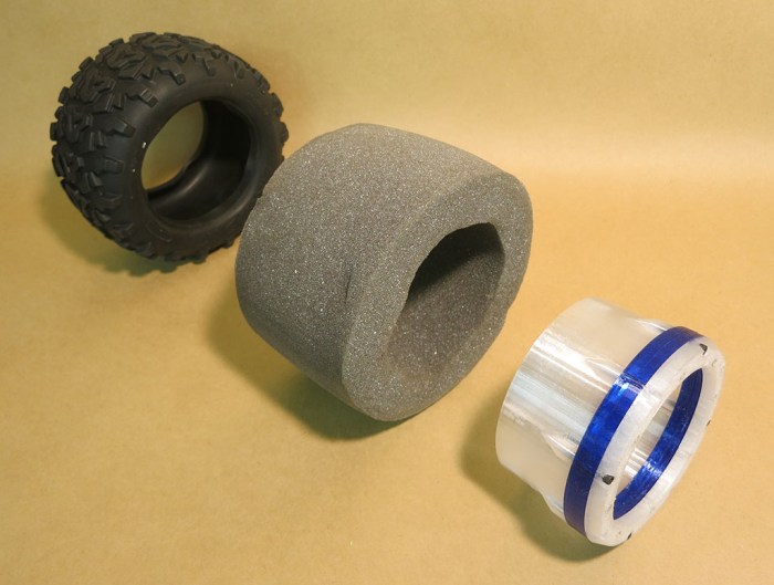
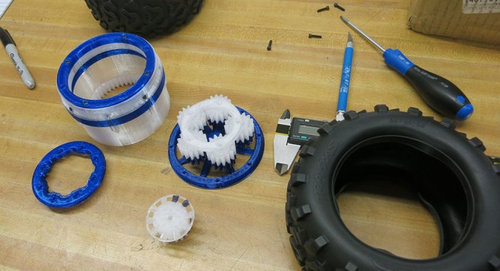
The freshly 3D-printed planetary gears added an unforeseen challenge. They have yet to wear in to each other and still have some rough spots. Combined with a tight fit (by design, to minimize backlash) this translated to high stiction requiring more power sent to the motor before it would start turning. At the moment, the wheel is spinning in open air and required little power to keep turning once it started. The large difference between startup power vs. runtime power translated to a tendency to overshoot on startup. This behavior is visually similar to a too-large P value and hard to tease them apart when tuning manually.

A well-tuned PID control system could handle this properly, but we’re not there yet. In the short term, the plan is to put these wheels on a test chassis so we could see how it works as actual propulsion. Also, installing the wheel on a chassis (and putting a workload on it) would increase the power needed to keep the wheel turning. Narrowing the difference between startup power and runtime power will hopefully help make fine-tuning the control loop easier.

Rover Wheel’s First RoboClaw Test Run Foiled By Encoder

Once we had all the parts of our 3D-printed rover wheel we assembled the first prototype. Then we brought it to one of our local makers’ SGVHAK meetup and hooked it up to a RoboClaw motion controller. The first half of the night was spent figuring out the computer software end of things. The RoboClaw configure software “Ion Studio” is Windows-only, whereas the Python software on hand is expected to run on a Linux distribution, most likely Ubuntu.

The software configuration settled on Windows running Python code inside WSL. (Windows Subsystem for Linux.) Python inside WSL couldn’t access the USB serial port unless given superuser privileges. (UPDATE: Should have tried adding user to dialout group.) Not ideal, but enough to get us going. Also worth mentioning: the two pieces of software (Ion Studio and Python) are unable to share the port. One must be shut down before the other could gain access to the port. Once all the above were squared away, we could send commands to RoboClaw from Python command line and commence the second half of the night: learning how to control wheel motion with RoboClaw.

The motion we saw was rough. Some of it could be attributed to the imprecision of 3D printed parts. But we suspected something else contributed to the jittery motion we saw. We suspect the PID tuning is far off the mark, and the acceleration / deceleration numbers are not the best. But the root culprit was traced down to the square wave signal from the optical encoder. We need the signal to be a clean square wave before any of those other tuning parameters could function reliably. Hooking the encoder output pins to an oscilloscope showed a ragged signal that would mislead the RoboClaw as to the physical movement of the assembly. It’s pretty hopeless to try tuning the other parameters without accurate motion feedback.

Bad Encoder Waveform

The encoder signal will need to be fixed before we come back to PID tuning & friends.

Our prime suspects for causing this waveform are:

  1. Poor electrical connection
  2. Insufficient power delivered to the IR emitters in the encoder.
  3. Problem with the 3D-printed slotted wheel.

SGVHAK Rover Mentioned By Pasadena Now

pasnow-caltech-03
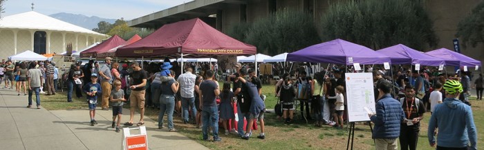
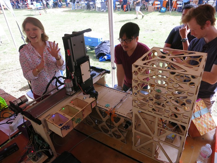
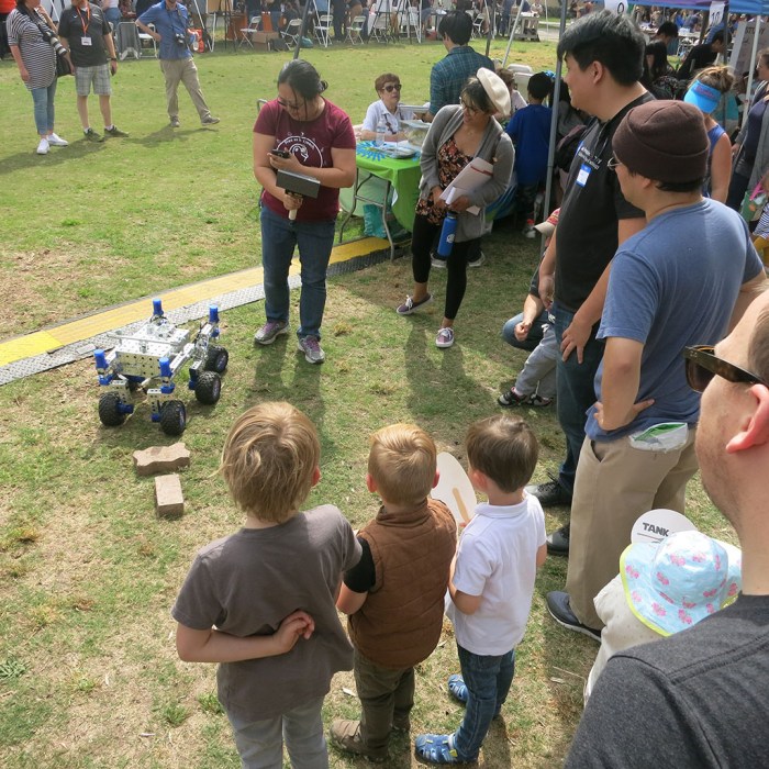
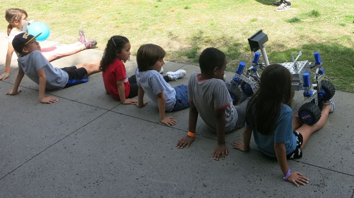
The rover made an appearance in the local news Pasadena Now as picture #3 in the photo gallery. (As did I, though I was not named and the picture only shows me from mid-torso down.) It’s cool to see that the local newspaper editor looked over their pictures of Caltech’s Science for March event this past weekend and chose the rover as one of the top ten to include in the gallery.

I think I even remember this photographer. (People wielding SLR cameras are few and far in between in this day of cell phone cameras.) I’m a little sad we didn’t speak, which resulted in the wildly inaccurate photo caption. I didn’t get to promote the JPL Open Source Rover project, nor SGVHAK’s role in beta testing the build instructions. Oh well.

The NASA stickers on the wheels serve a functional purpose: since the rover will be running on dirt and grass, we risk contamination and possible jamming if any debris got into the open faced planetary gearbox. The most convenient wheel cover turned out to be NASA stickers handed out by another booth. It’s almost the right diameter and a perfect fit for our mars rover inspired robot project.

Rover Begins With Wheel Assembly

Back when the SGVHAK rover started, we started literally from the ground up by building the wheels. The wheels were one of the more significant differences from the baseline rover design and we wanted to get a head start on problems.

Once the initial parts of the planetary gear hub for rover wheel were 3D printed, we started to get an idea of how well things fit our target design constraints: All of the 3D printed parts must fit between two non-3D printed components. On the outside: the tire (and foam tire insert) of a remote control monster truck. On the inside: an electric motor.

Wheel Hub

The space constraints pointed us towards a planetary gear as the best approach for the reduction gear in this drivetrain. In addition to the planetary gears, the space must accommodate the components for a rotary encoder so we can set up a closed loop motion control system for wheel motion. We don’t just want the wheel to turn – we want it to turn at specific rates, to reach specific positions, and we need an encoder to close the feedback loop on what the wheel is actually doing.

Planetary Gear

Once all the mechanical bits are assembled, it will be time to hook it up to the motion control circuit. We’ll be using RoboClaw boards from Ion Motion Control for this project.

SGVHAK Rover at Caltech Science for March

Caltech QuadSGVLUG has a booth at Caltech’s Science for March event which means another public outing for SGVHAK Rover. The event itself featured a lot of groups affiliated with Caltech showing what they have offer to the visiting public. The weather cooperated with a nice sunny day for people to stop in for a look.

Pasadena City College, which is basically next door, had a strong presence with many student groups showing off their projects. Here’s a machine that takes poker chips in a chute (right) and sorts them by color into bins (lower left).

Poker chip sorter

JPL brought in some model rover wheels. These were not made with the same material of real rover wheels, but they are actual size. They represent the wheels of Sojourner, the Spirit/Opportunity twins, and Curiosity rover.

Rover wheels actual size

Our SGVHAK rover started the day sitting on the table.

Rover on table

But it didn’t take long before the rover hit the road and started demonstrating its chops by climbing some bricks.

Rover Brick Demo

A demonstration of suspension capability is to sit down in front and let the rover climb over your legs. One of the times this was demonstrated, it caught the attention of a bunch of children who ran and lined up to be run over too.

Kids lining up to get run over

All this climbing was great, but it took a toll on the rover. The stresses started loosening up some screws and the right-front wheel started dangling on one final loose screw.

Rover Wheel Dangling

Rover Wheel Last Screw

A little field repair was in order – stealing screws from elsewhere on the rover to get it back up and running again.

Rover Wheel Field Repair