Belkin Play N600 Wireless Router

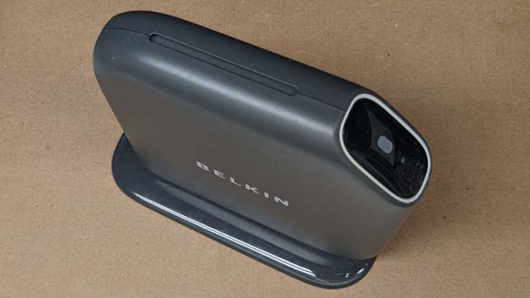
When wireless routers became commodity electronics, industrial design became a differentiation factor. They used to all be uniformly boxes with antennae sticking out of them, but now they come in many shapes and sizes. There’s definitely a market catering to people who don’t like the look of antennae sticking out. This retired Belkin router was from a line of similar designs, with its antennae completely enclosed inside a slickly designed exterior.

My favorite part of this design is a subtle passive cooling system that did not call attention to itself. Between the main body and the foot is a small gap, and here’s where cooling air can be pulled in from the bottom of the unit.

Normal convection forces would send warm air up to the top of the case, where it exits this slot acting as exhaust. I love it.

Only two fasteners are accessible, one hidden under the bottom label.

Removing those two screws allowed the foot to be removed. The cooling intakes are now clearly visible.

Those two screws also help hold the enclosure together. Of course, there are plenty of plastic clips all around as well.

With the first side panel removed, we can see the main circuit board held between the central plastic frame and the other side panel.

Four more screws and many clips later, all major components have been separated.

The circuit board is not very tightly packed. Metal pieces to the top and the left are its WiFi antennae, set at ninety degrees to each other for mutually complementary reception. I’m sure their shape is an intentional design with tradeoffs versus the traditional stick, but I don’t know enough RF voodoo magic to begin to guess at what’s going on. Speaking of RF voodoo magic… I see no metal RF shields covering any part of this circuit board. I see provisions for them on this board in the form of silvery solder square outlines above and below the chip marked Broadcom, but unused.

Here we see more unused provisions. This router has a single USB port and a single rear status LED. On the circuit board we can see provisions for a second LED, just above the text labeled LED6. Plus provision for a second USB port, with unused pins labeled 5, 6, 7, and 8. Adding a second USB port would require unsoldering this USB connector and replace it with a double-deck equivalent. The LED housing is already all set up for a second LED.

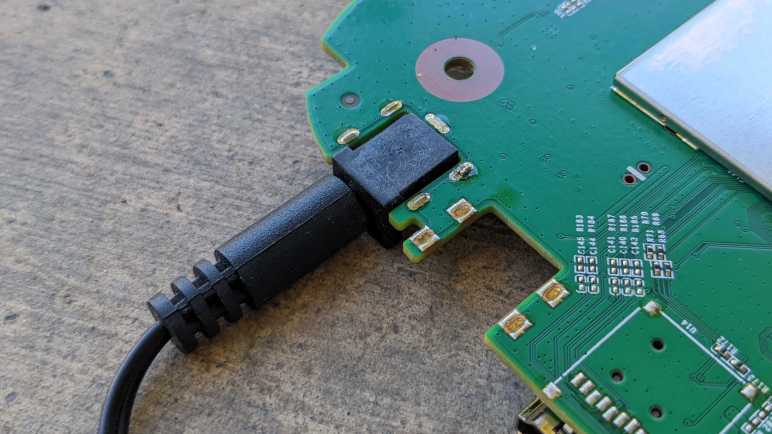
J12 here is weird, it seems to be a 2-pin header being used as an antenna wire guide. If the pins were straight, I would say this was just a hilarious coincidence with the wire getting caught between pins, but the pins have been bent inward at the factory, what other purpose might that serve but to keep the wire in place?

Melnor Garden Hose Watering Nozzle

As a change of pace from electronics teardowns: I’m taking apart something with no electronics at all: my very old garden hose watering nozzle. It’s been leaking for years, which is why I’ve had to turn the faucet off when this is unused. Otherwise, it wastes water dropping out from the front and the back. But recently it started failing in a new way: there is now a horizontal curtain of water when I pull its lever, spraying water everywhere from just behind the spray pattern adjustment knob. It is finally time for this guy to go, but not before I take a look inside.

A single Philps-head self-tapping plastic screw held the spray pattern selector knob in place.

With the selector knob removed, its seal and detent mechanism falls out easily. The white spring-loaded mechanism pushes into dimples in the selection dial for that satisfying “click” when we are lined up for a spray pattern. The rubber seal has lost its flexibility and became rigid with age. It could no longer seal against water pressure, causing this nozzle’s retirement.

Two more screws were visible and promptly removed, but this plastic piece did not release easily. I broke a bit of the lip (visible in upper-right area of the rim) trying to pull it out. No other fasteners or retention mechanism were visible.

If I could not pull it, perhaps I could push it? I started working on the back end. Unthreading the adjustment nut all the way allowed its removal.

Pushing on the thread, the front face popped free along with the piston assembly. A coat of rust clearly designated regions that had years of water exposure.

Inside the handle body.

Inside the front face.

Intact piston assembly.

I could only partially disassemble the piston assembly. In use the rear seal and its washer moves against the piston shaft and thus could be slid off the end. The spring followed easily.

However, the front seal and the X-shaped plastic guide keeping it centered in the cylinder never had to move and now it is held in place by rust. The plastic guide showing signs of abuse of my removal attempt. Even if replacement seals were available, I would not have been able to replace this particular wear item.

The lever hinge pin is riveted in place, requiring a drill to free it.

And finally, the soft handle surround was cut free of the metal core with a box-cutter knife. Doing this reminded me of that scene in Terminator 2 where the T-800 cut off living tissue covering its arm to expose the metal endoskeleton.

Taylor Food Thermometer

This Taylor food thermometer display went blank and stayed blank even when given fresh batteries, so it’s getting the teardown treatment before disposal. It appears to be a design that the company has made for many years with slight variations, here is a close cousin I found on Amazon. (*) I’ve found no mentions of repair instructions or replacement parts, this is a disposable device.

The first thing I wanted to check is construction of the temperature probe. There were two possibilities:

  1. The temperature probe is mostly metal, and the sensor is near where the wire is attached. This would be dependent on a metal with high heat conductivity to carry heat from the tip of the probe to the sensor at its base.
  2. The temperature probe is mostly hollow tube, and wires run the entire length of the probe to a sensor at the tip.

I started opening it up and got this far before slicing myself open on a sharp metal edge.

With a ritual blood sacrifice to the teardown gods, I decided to stop here. It is far enough for me to conclude that possibility #2 is correct and the probe is mostly hollow tube with the sensor at the tip.

Next I started prying against the shiny top surface of the device and found it was merely a cosmetic facade held on with glue and not hiding any fasteners underneath.

Four fasteners were visible behind the display so I started work there.

There is a piezo sound element embedded in the back, and a circuit board inside. Under that black blob is likely a chip that runs the whole show. What struck me are the areas to the left of the blob: there are a few round test points, but many more rectangular pads for components that aren’t there. Are they for calibration? Are they for adjustment? Are they to activate/deactivate features for other products in the lineup? Maybe a combination of all of them?

I see a single screw for the base. Removing that screw freed a small piece of plastic but did not free the entire base. However, it did let me see inside the base and distinct signs of additional fasteners.

Aha, I forgot to check for fasteners hidden under squishy feet.

With those screws removed, we can see the base has no active components. It has the battery enclosure, socket for the temperature probe, and a circuit board for all the switches and buttons to operate the device. All the components appear to be in good shape, I see no obvious signs of damage that might explain why the device stopped working.

The display is a custom LCD unit held on with the squishy conductive stuff I’ve seen before in tearing down electronics but didn’t know anything about. This time I went online and found this electronics StackExchange thread. Which linked to this one. Formally “Elastomeric connector” and less formally “zebra strips” (though a search with those terms also need to have “electronic” in the keyword list or else we’d get stuff about zebra the animal.)

I don’t plan on keeping the circuit board or any of the components on board, but I’ll hang on to the LCD for the moment. If I get around to probing the LCD in the future I’ll need to fabricate my own circuit board to make contact with the zebra strip. I can take this picture showing the connector pitch, but sadly I’ve already lost horizontal alignment reference and that’ll be a problem I have to tackle later.


(*) Disclosure: As an Amazon Associate I earn from qualifying purchases.

Surface Mount Repair Practice with Mr. Robot Badge

Years ago at a past Hackaday Superconference, I had the chance to play with a small batch of “Mr. Robot Badge” that were deemed defective for one reason or another. After a long story that isn’t relevant right now, I eventually ended up with a single unit from that batch with (at least) two dark LEDs in its 18×18=324 array of LEDs. I thought trying to fix it would be a good practice exercise for working with surface-mount electronics, and set it aside for later. I unearthed it again during a recent workshop cleanup and decided it was a good time to check my current surface mount skill level.

I’m missing a few tools that I thought would be useful, like a heat plate or hot air rework station. And while my skills are better than they were when I was originally gifted with the badge, it’s still far from “skilled” at surface mount stuff. (SMD for surface-mount devices, or SMT for surface-mount technology.) One relatively new tool is a dedicated LED tester, and I used it to probe the two dark LEDs. One of them would illuminate with the test probe in place, and a dab of solder was enough to make proper electrical connection and bring it to life. The other one stayed dark even with test probe and would need to be replaced.

Looking in my pile of electronics for a suitable doner, I picked out my ESP32 dev module with a flawed voltage regulator that went up in smoke with 13V DC input (when it should have been able to handle up to 15V DC). This module has a red LED for power and a blue LED for status. I probed the red LED and found it dead, but the blue LED lit up fine. Between “keep looking for a red LED” and “use the blue one in my hand” I chose the latter out of laziness. This is a practice exercise with low odds of success anyway.

Lacking a hot air rework station or a hot plate, I didn’t have a good way to heat up both sides of a LED so there was a lot of clumsy application of solder and flux as I worked to remove the dead badge LED. It came apart in two pieces, so I practiced removal again with the dead red LED on my ESP32 dev module. Once I removed it intact, I tossed it aside and used my newfound (ha!) skill to successfully remove the blue LED in one piece. I might be getting the hang of this? Every LED removal was easier than the last, but I still think a hot air station would make this easier. After I cleaned up the badge LED pads, I was able to solder one side of the salvaged LED then the other. I could see a little bit of green on one side of the LED indicating polarity, so I lined it up to be consistent with the rest of the LEDs on the badge.

I turned on the badge and… the LED stayed dark. It then occurred to me I should have verified the polarity of the LED. Pulling out the LED tester again I confirmed I have soldered it on backwards. Valuable lesson: LED manufacturers are not consistent about how they used the little bit of green on a LED to indicate polarity. So now I get to practice LED removal once again, followed by soldering it back on the correct way. I would not have been surprised if the blue LED had failed after all this gross abuse. On the upside a failure would motivate me to go find another red LED somewhere.

Here is a closeup of the problematic area on the badge. The circle on the right was the LED that just needed a bit of solder for proper contact. The circle on the left represents the scorched disaster zone that resulted from SMT rework amateur hour as I unsoldered and resoldered multiple times. The little blue LED clung on to life through all this hardship I had inflicted and shone brightly when the badge was turned on. I’ll call that a successful practice session.

[Update: I didn’t originally intend to do anything with the badge beyond soldering practice, but I looked into trying to write my own code to run on the badge and successfully did so.]

Window Shopping: Cutra Wondercutter Ultrasonic Knife

During an online video meetup with some makers, I learned that consumer-level ultrasonic knives exist. One member of the meetup was taking theirs apart for some reason I’ve now forgotten, I just remembered his quick demo of the handheld cutting blade cutting through a 3mm thick sheet of acrylic. It wasn’t exactly “hot knife through butter” (maybe cold knife through refrigerated butter) but certainly far superior to what I could do with my X-Acto #11 blade.

I had known of ultrasonic tools in the medical field, specifically dental tools. I also had some idea they existed in the realm of industrial manufacturing equipment. But something I could conceivably buy for my own workbench? That’s news to me. Unfortunately, the person on the video wasn’t able to give me much information to go on, so I started searching for “ultrasonic knife” from my usual list of tool vendors. Unsurprisingly, I got a hit at McMaster-Carr: Item #3415N11 Fast-Cutting Ultrasonic Precision Knife. Visually, this looks like the same device I saw being disassembled at the meetup. But McMaster-Carr didn’t give me very much information on this device, not even some things I consider basic like make and model for further evaluation.

A search for “Ultrasonic Knife” on Amazon would give me several multi-thousand-dollar industrial machines, and also this listing. (*) Titled “The Wondercutter S” it looks right, but this listing felt odd for several reasons. The brand is listed as “MICRO-MAKE” but there’s nothing else by that brand name. There is also a logo on the device absent from the McMaster-Carr listing. It is stylized so I couldn’t quite decipher it to letters, but it is definitely neither “Wondercutter” or “MICRO-MAKE”. This listing didn’t give me the confidence I needed to commit several hundred dollars, despite Amazon Prime guarantees.

Continuing online search, I also got a hit at Home Depot which was a mild surprise. I had not associated the big orange DIY home improvement store with high tech tools. From this listing I got a brand name “CUTRA” which explains the stylized logo I couldn’t read earlier.

Now that I have a brand name, I found its company site and their own product site. It appears to be a Korean company and I finally got the specifications I could sink my teeth into. There were also a lot of demonstrations videos on what this device could do, the one that got my attention was cleaning up supports for 3D printing. I’ve never enjoyed cleaning up supports, and I’ve had a few dangerous close calls with my trusty X-Acto blade doing so. A couple of hundred dollars is a significant investment, but if it saves me a single hospital visit that would make the item worthwhile.

From this site I also learned that Wondercutter was crowdfunded as an Indiegogo project back in 2017. Well, I definitely missed the early bird backer special of $258 USD! I just have to pay retail now. Elsewhere on the site I saw I could order direct from Korea, but they have signed an official distributor for United States: Micro-Mark. Now this is a name I know from my scale plastic model days! I used to be a very good Micro-Mark customer buying Tamiya paints (they’ve all since dried out) and small model-building hand tools (I still use some of them).

Well, at least this explains the mystery branding of “Micro-Make” on that Amazon listing, it was a typo of Micro-Mark. There is actually a Micro-Mark storefront on Amazon (*), but with only a subset of the full catalog. For example, they sell replacement Wondercutter blades (*) but they don’t sell the Wondercutter itself on Amazon. Why would they leave it open for an imposter vendor to take away potential Amazon sales? That’s a curious business decision. Micro-Mark claims to be the exclusive distributor for North America, and I can see they are listed as vendors on sites like Walmart. But I’m not sure what’s the point of going through Walmart (or Home Depot or Amazon) if Micro-Mark is actually the distributor. It seems to make more sense to order one direct from Micro-Mark’s own website.


(*) Disclosure: As an Amazon Associate I earn from qualifying purchases.

Brother TZe Label Tape Cartridge Teardown (Don’t Put Secrets On Your Labels!)

While organizing my workshop, I labeled a lot of things with my label maker (Brother P-Touch PT-D400) and used up a cartridge. A common complaint with these TZe label tape cartridges is that they are really expensive. So now that I have an empty cartridge, I thought I would take it apart to see if I can see anything that justifies its expense. It turned out to be far more sophisticated than I had originally expected, but I still don’t know if I would call its cost “reasonable”. Plus I found an interesting security concern. Don’t use label makers for confidential information!

The only thing we can really see from the outside is a horizontal window designed to let us see how much tape is left. When full, there’s white visible behind the light blue area. That white spool’s diameter decreases as the tape is consumed, gradually running to what we see in this picture where very little white is visible behind the blue.

Looking around the perimeter, I see several little clips holding the lid to the body plus this white tag telling me what label tape is inside. I expect that I would have to cut this white tag along the seam, pop those little clips loose, and it should fall apart.

It did not.

Majority of holding force actually came from these posts that fit very tightly into their sockets, not the clips or the sticker. Dimension precision in injection-molded plastic is directly correlated to cost, so that’s where some of the money went: it’s pretty expensive to keep these posts and their corresponding sockets within the exact dimensions to fit and grip tightly.

After I opened up the cartridge, I see I had drastically underestimated the complexity inside. There are actually four spools, a few rollers, and many guides to keep three tapes of materials flowing properly.

Here are all the components of the cartridge. Multiple spools, and a few springs to maintain tension. I had expected a single spool of tape that gets spit out, so this is far more complex than I had anticipated. There are actually three spools of material: The white adhesive backing, the black ink (with take-up reel), and the clear laminate layer.

Here is a closeup of the clear laminate spool and the white adhesive backing spool. The clear laminate spool has black stripes in this picture because that’s how the cartridge signals the end. There were ~20cm left of this zebra stripe, not that I can think of much I could do with it.

Here is the other side, showing the adhesive backing still usable on what’s left of the white reel. It looks like remaining white backing can still function as double-sided tape if I wanted to put it to work.

The black ink tape was a surprise. It is a pair: a dispenser reel for fresh material and a takeup reel for used ink. What’s super interesting here is that the takeup reel has a clearly legible negative image of everything that has been printed. Unspooling the takeup reel a bit, we can clearly see that my most recent label was for a batch DC buck converters showing their adjustable voltage range and maximum of 5 amps capacity.

A valuable lesson from this teardown: avoid confidential information when using a label maker, because a motivated dumpster-diver can read that information off your discarded empty label tape cartridges.

Window Shopping LovyanGFX

One part of having an open-source project is that anyone can offer their contribution for others to use in the future. Most of them were help that I was grateful to accept, such as people filling gaps in my Sawppy documentation. But occasionally, a proposed contribution unexpectedly pops out of left field and I needed to do some homework before I could even understand what’s going on. This was the case for pull request #30 on my ESP_8_BIT_composite Arduino library for generating color composite video signals from an ESP32. The author “riraosan” says it merged LovyanGFX and my library, to which I thought “Uh… what’s that?”

A web search found https://github.com/lovyan03/LovyanGFX which is a graphics library for embedded controllers, including ESP32. But also many others that ESP_8_BIT_composite does not support. While the API mimics AdafruitGFX, this library adds features like sprite support and palette manipulation. It looks like a pretty nifty library! Based on the README of that repository, the author’s primary language is Japanese and they are a big fan of M5Stack modules. So in addition to the software technical merits, LovyanGFX has extra appeal to native Japanese speakers who are playing with M5Stack modules. Roughly two dozen display modules were listed, but I don’t think I have any of them on hand to play with LovyanGFX myself.

Given this information and riraosan’s Instagram post, I guess the goal was to add ESP_8_BIT composite video signal generation as another supported output display for LovyanGFX. So I started digging into how the library was architected to enable support for different displays. I found that each supported display unit has corresponding files in the src/lgfx/v1/panel subdirectory. Each of which has a class that derives from the Panel_Device base class, which implements the IPanel interface. So if we want to add a composite video output capability to this library, that’s the code I expected to see. With this newfound knowledge, I returned to my pull request to see how it was handled. I saw nothing of what I expected. No IPanel implementation, no Panel_Device derived class. That work is in the contributor’s fork of LovyanGFX. The pull request for me has merely the minimal changes needed to ESP_8_BIT_composite to be used in that fork.

Since those changes are for a specialized usage independent of the main intention of my library, I’m not inclined to incorporate such changes. I suggested to riraosan that they fork the code and create a new LovyanGFX-focused library (removing AdafruitGFX support components) and it appears that will be the direction going forward. Whatever else happens, I now know about LovyanGFX and that knowledge would not have happened without a helpful contributor. I am thankful for that!

Roku Premiere (4620X “Cooper”) Power Socket

When I tear down some retired electronic device, I try to salvage what I know I could reuse and that usually includes the power supply. A few of these salvaged power supplies have already found use, but sometimes I’m hindered by the fact I saved only the power supply and not its corresponding power socket. Sometimes I can replace the connector, but sometimes not. As a result, I’ve resolved to put more effort into saving the matching socket as well.

Which brings me to this Roku Premiere 4620X (“Cooper”) that was given to me for teardown after it was retired. I tried to unsolder its power socket, but I quickly realized I was in trouble. When I put my soldering iron tip on the soldered point and… absolutely nothing happened. Looking at the circuit board I can see there’s a lot of copper tied to ground, which four of five pins on this power socket is attached to. That’s a lot of heat dissipation capacity fighting against my iron’s efforts to melt solder.

I think a hot air rework station might be able to help here, but I don’t have one and my lack of skill means there is a high risk of softening the black plastic as I blast hot air. If I distort the plastic to a point where the power plug could no longer fit, that would defeat the purpose. This concern also definitely ruled out my paint-stripping hot air gun.

I think the best tool for this job is a hot plate designed for installing surface-mount electronics components. Their hot metal surface area could in theory do this work at a lower temperature than blowing hot air. I wouldn’t necessarily need a big one, either. A tiny little one would be enough to do this job.

But I don’t have any of those tools, so I fell back to plan of last resort I call “mechanical separation”. That is my fancy way of saying I whipped out a saw and cut the circuit board around the socket.

Sometime in the future, when I decide I want to reuse this power supply and its matching power socket, I hope to have better tools for the job of separating the socket from its (now much reduced) circuit board.

ESPHome Remote Receiver Test: Simplistic Shooting Game

I salvaged an infrared remote control receiver from a Roku Premier 4620X (“Cooper”) and dumped out some codes using an ESP32 microcontroller running ESPHome software’s Remote Receiver component. This is great, but before I moved on, I ran a simple introduction to actually using it. The “Hello World” of ESPHome remote receiver, so to speak.

The idea is a very simple shooting game. I will add an LED to the breadboard connected to GPIO 18. I will count to five seconds in an on_loop lambda and illuminate the LED using ESPHome GPIO output component. Once illuminated, it will wait for the signal sent by a Roku RC108 remote when the “OK” button is pressed. Once received, I will darken the LED for five seconds before turning it back on. With this very simple game I pretend to “shoot out” the light with my remote.

It was silly and trivially easy as far as shooting games go. Infrared remote controls are designed so the couch potato doesn’t have to aim very accurately for them to work. The emitter sends out the signal in a very wide cone, and the receiver is also happy to receive that signal from within a wide cone. If I am to evolve this into an actually challenging target practice contraption, I would have to figure out how to narrow the cone of effectiveness on the emitter, or the receiver, or both!

But that was not the objective today. Today it was all about dipping my toes in that world before I continued with my Roku teardown. I wanted to keep the hardware trivial and the code simple, so here is the ESPHome code excerpt for this super easy shooting game:

esphome:
  on_loop:
    then:
      - lambda: |-
          if (id(ulNextOn) < millis())
          {
            id(led_01).turn_on();
          }

status_led:
  pin:
    number: 2

output:
  - platform: gpio
    pin:
      number: 18
      inverted: true
    id: led_01

globals:
  - id: ulNextOn
    type: unsigned long
    restore_value: no
    initial_value: '0'

remote_receiver:
  pin:
    number: GPIO36
    inverted: true  
  dump: nec
  tolerance: 10
  on_nec:
    then:
      - lambda: |-
          unsigned long ulTurnOff;
          
          if (0x55AA == x.command)
          {
            id(led_01).turn_off();
            id(ulNextOn) = millis() + 5000;
          }

Roku Premiere (4620X “Cooper”) Infrared Receiver

Looking over the circuit board of a Roku Premiere 4620X (“Cooper”) I saw a lot of things that might be fun to play with but require more skill than I have at the moment. But that’s fine, every electronics hobbyist has to start somewhere, so I’m going to start small with the infrared remote control subsystem.

Consumer infrared (IR) is not standardized, and signals may be sent on several different wavelengths. Since I want to play with the Roku RC108 remote control unit, I needed to remove the infrared receiver of its corresponding Premiere 4620X in order to guarantee I have a matching set. This is a small surface-mount device protected by a small metal shield that I could fold out of the way.

Once the shield was out of the way, I could turn on the Roku and probe its pins with my voltmeter to determine the power supply pin (constant 3.3V) the ground pin, and the signal pin (mostly 3.3V but would drop as I sent signals with the remote.) I then removed this receiver with my soldering iron and connect this tiny part to a set of 0.1″ spacing headers so I could play with it on a breadboard.

In this picture, from top to bottom the pins are:

  • Ground
  • (Not connected)
  • Power 3.3V
  • (Not connected)
  • Active-low signal

I installed it on a breadboard with an ESP32, flashed with ESPHome which is my current favorite way to explore things. In this case, ESPHome has a Remote Receiver component that has decoders for many popular infrared protocols. What if we don’t know which decoder to use? That’s fine, we can set the dump parameter to all which will try every decoder all at once. For this experiment I chose an ESP32 because the of its dedicated remote control (RMT) peripheral for accurate timing while decoding signals. After I get something up and running, I might see if it works on an ESP8266 without the RMT peripheral.

With dump parameter set to all listening to a Roku RC108, I got hits from the JVC, LG, and NEC decoders. And occasionally I would get a RAW message when none of them could understand the signal. If I hold the [up] button, I get one instance of:

[18:55:50][D][remote.jvc:049]: Received JVC: data=0x5743
[18:55:50][D][remote.lg:054]: Received LG: data=0x57439867, nbits=32
[18:55:50][D][remote.nec:070]: Received NEC: address=0xC2EA, command=0xE619

But just the first one. All following hits look like this, and they repeat for as long as I held down the [up] button.

[18:55:50][D][remote.jvc:049]: Received JVC: data=0x5743
[18:55:50][D][remote.lg:054]: Received LG: data=0x57439966, nbits=32
[18:55:50][D][remote.nec:070]: Received NEC: address=0xC2EA, command=0x6699

Then if I press the [down] button on the remote, the first interpreted signal became:

[18:55:52][D][remote.jvc:049]: Received JVC: data=0x5743
[18:55:52][D][remote.lg:054]: Received LG: data=0x5743CC33, nbits=32
[18:55:52][D][remote.nec:070]: Received NEC: address=0xC2EA, command=0xCC33

Then it would repeat the following for as long as [down] was held:

[18:55:53][D][remote.jvc:049]: Received JVC: data=0x5743
[18:55:53][D][remote.lg:054]: Received LG: data=0x5743CD32, nbits=32
[18:55:53][D][remote.nec:070]: Received NEC: address=0xC2EA, command=0x4CB3

Looking at this, it looks like JVC is overeager and doesn’t actually understand the protocol as it failed to differentiate up from down. That leaves LG and NEC decoders. To find out which is closer to the Roku protocol, I started tightening the tolerance parameter from its default of 25%. When I have it tightened to 10%, only the NEC decoder returned results. Even better, each button returns a repeatable and consistent number that is different from all of the others. Even if Roku isn’t actually using a NEC protocol, using the NEC decoder is good enough to understand all its buttons. I used the NEC decoder to generate this lookup table.

Roku Remote ButtonDecoded Command
Back0x19E6
Home0x7C83
Up0x6699
Left0x619E
OK0x55AA
Right0x52AD
Down0x4CB3
Instant Replay0x07F8
Options0x1EE1
Rewind0x4BB4
Pause0x33CC
Fast Forward0x2AD5
Netflix0x34CB
Sling0x58A7
Hulu0x32CD
Vudu0x7788

I think I got lucky this time with the NEC decoder. I had another infrared remote control in my pile of electronics (JVC RM-RK52) and none of the ESPHome decoders could decipher it, just RAW data all the time. Alternatively, it’s possible that remote is on a different infrared wavelength and thus this particular receiver is only picking up fringe gibberish. I’ll put the JVC remote back in the pile until I am in the mood to dig deeper, because right now I want to quickly play with this salvaged infrared system.