Conair Hair Clipper (HC318R)

I have a set of retired hair clippers on the teardown to-do list. My hair are like bristles in a stiff wire brush, and wears down cutting blades quickly, fresh clippers only keep their “oh wow, this cuts nice” feeling for the first half-dozen or so sessions. I use one for a few years until its rechargeable battery degrades. By that point, its blades are dulled enough to be tugging and pulling hair while cutting. Between the battery and the blade, it was time for a new one.

I’ve been avoiding these teardowns because I knew it would get messy, given the short fragments of hair clinging to every surface of these clippers via either lubrication oil or static electricity. I knew I will find small pieces of hair everywhere for weeks after each teardown. But the paper liner on my workbench is starting to get dirty enough for replacement, and I saw an opportunity: I can do these messy teardowns and throw away the liner, hopefully easing cleanup.

First up is the Conair HC318R. Information embossed on the back of the device was hard to photograph, but it says:

(C) CONAIR CORPORATION, EAST WINDSOR
NJ 08520 / GLENDALE, AZ 85307
MODEL HC318R 4.5V DC 1000mA
USE WITH ADAPTER CA12
MADE IN CHINA
HOTLINE 1-800-3-CONAIR

Next to this information is a small tag informing me the device contains nickel-cadmium battery and must be recycled or disposed of properly. I expect to find three cells wired in series given the 4.5V DC written on the device.

If somebody has the clipper but not the charger, here are the specifications on its label. The charging port looks to be a pretty standard barrel jack wired to be center-positive.

There were two very large and easily accessible Philips-head screws on the blade. Removing them frees the outer blade, allowing us to clean inside.

The inner blade lifts away to expose the motor-driven crank.

Opening the enclosure allows a look inside.

Behind the motor sat the expected three-cell nickel-cadmium battery pack, each cell is the size of an AA battery.

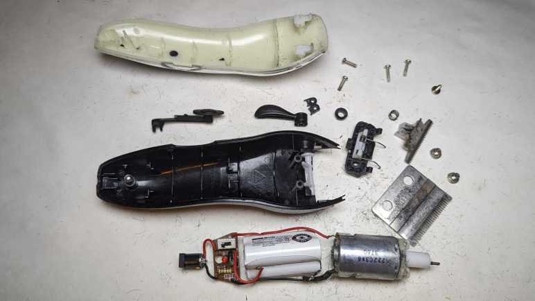
There were no further fasteners holding the working bits in place. Once the enclosure was opened, the electrical guts are easily lifted out.

The battery pack manufacturer is BYD, the battery company that grew into an automotive manufacturing conglomerate. I measured less than 2V across its terminals, so it’s either severely discharged or there’s a dead cell in the pack. Neither would be a surprise after years of use followed by more years of waiting for teardown.

Thanks to decades of manufacturing at scale, nickel-cadmium batteries are cheap. They are also hardy and tolerant of abuse, which cut costs further because they don’t need sophisticated battery management electronics like lithium-based batteries do. Here we have just a small single-layer circuit board housing the power switch, two resistors, two diodes, and one light-emitting diode. M+ (motor positive) is connected to one side of the switch opposite B+ (battery positive). M- location was unused: it had a short trace to diode D3 which was also absent. Motor negative was wired to battery negative off board then a single wire led to B- on this board, which was electrically connected to the other end of the absent diode D3. Apparently, they decided D3 was unnecessary! Finally, L+/L- lead to the AC adapter barrel jack for charging.

The motor is marked with 222C3V6 3760 but I didn’t find much from that information. The crank is a piece of friction-fit plastic and slid off unexpectedly easily. The motor mount was installed with two small Philips-head screws and easily removed.

The barrel jack will stay with the AC adapter for possible future reuse. The motor will join many other salvaged motors. The battery pack will go in the nickel-cadmium battery recycle bag. The circuit board will go into the electronic recycle box. Metal blade and fasteners will go into metal recycle bin. Remaining plastic enclosure bits will go into landfill along with many bits of hair. I didn’t put too much effort into cleaning the workbench, because I had more hair clippers for teardown.

FreeCAD Notes: Mirror

FreeCAD offers multiple ways to constrain a distance: strictly along vertical axis, strictly horizontal, or the shortest distance between those two points. This is more direct than Onshape’s way of heuristically guessing user intent, and I can see myself learning to like it. What I will miss, though, is Onshape’s sketch mirroring mechanism that can mirror along arbitrary lines and maintain relationship with the original. FreeCAD 0.20.2 doesn’t seem to do either.

Many of my mechanical designs have symmetric features. Just as one example, a commodity micro servo is mounted via two tabs, each held with a small screw. The mounting tab and screw hole is symmetric about the center. I prefer not to duplicate effort by drawing two tabs and two screw holes. In Onshape, i can draw just one side and a line on my sketch representing the center. I can then use the mirror function to generate the other side. If I need to refine my sketch later, I can fine tune dimensions on the side I drew and Onshape will automatically update the mirrored side to reflect my changes.

FreeCAD’s Sketcher workbench does have a “Mirror Sketch” feature, but it does not mirror about arbitrary lines in the sketch. It can only mirror about the X axis, the Y axis, or the Origin point which mirrors both X and Y. Here I’ve sketched out one quarter of a symmetric part (Displayed jn green) and mirrored it three times (about X, about Y, and about Origin. Displayed in white.) to create the entire perimeter of this test.

Furthermore, I didn’t get to select which feature to mirror. “Mirror Sketch” mirrors everything in the sketch and placed results in a new sketch, which seems to sever all association with the original sketch.

If I change a dimension in the original sketch, in this experiment the width, none of the mirrors were updated to reflect my change. There’s a “Merge sketches” feature to put everything back into the same sketch, but that doesn’t fix this problem.

There’s a good chance I can accomplish what I want with a different FreeCAD feature, much as how I wanted “Midpoint” and eventually found a solution via “Constrain symmetrical”. But as of this writing I haven’t found my desired functionality. Until I do, sketching symmetric features in FreeCAD will require duplicate effort sketching features that I could mirror in Onshape. I will then have to manually link duplicated features with “Constrain equal” so any future updates to critical dimensions will be properly propagated through symmetric features. This will not be a major dealbreaker against using FreeCAD, just mildly annoyed at the extra effort taking more time.

FreeCAD Notes: Distance

I’m on my FreeCAD learning journey and I’ve had to change some of my Onshape habits. For sketching, I was able to adapt from Onshape’s “Midpoint” constraint to FreeCAD’s “Constrain Symmetrical” once I figured out a workaround to avoid redundancy errors with FreeCAD’s implicit constraints.

I’m generally in favor of having one way to do something instead of offering multiple similar ways, so I’d be OK if it was a deliberate decision not to add a dedicated “Midpoint” constraint when “Constrain Symmetrical” is functionally equivalent. But I doubt it, because that’s not been the typical FreeCAD pattern. It already has two confusingly similar workbenches “Part” and “Part Design“, and multiple competing workbenches for assemblies. (It’s up to “Assembly3” and “Assembly4” now.) And right on the sketching constraints toolbar, where a “Midpoint” may have been deemed redundant, we have three separate tools to denote linear dimension: “Constrain horizontal distance”, “Constrain vertical distance”, and “Constrain distance.”

Each of these have valid use, because these distance constraints are driven by project requirements that may dictate we measure horizontally, measure vertically, or measure the direct line distance. Once I saw these three options listed side by side I immediately understood why they were there, but I was surprised because Onshape handled the problem differently.

In Onshape, there’s just a single dimension operation. In my experience it is usually a direct line measurement equivalent to FreeCAD’s “Constrain distance”. But sometimes I do need to constrain distance along a horizontal or vertical axis. In these cases, Onshape lets me drag the distance number away from the object. If I drag far enough away horizontally, it becomes a vertical distance constraint. The number is recalculated accordingly, and I can edit it afterwards as desired. A horizontal distance constraint is done similarly, by dragging the number away from the object either above or below vertically. This heuristic typically works well, but can be frustrating for features at a shallow angle: I would have to drag pretty far before Onshape understood I don’t want the shallow angle, I want horizontal/vertical.

With that experience in mind, I think I might come to prefer having three distinct and explicit methods to constrain a distance despite my typical preference to have a single way to do something. The only downsides with this approach are a bit of extra screen real estate taken up by the toolbar, and the fact I’ll eventually have to memorize three different keyboard shortcuts to become fluent at FreeCAD.

FreeCAD Notes: Midpoint

In between musing about VR projects and other random ideas, I’ve been returning to FreeCAD and learning my way bit by bit. After my initial introduction to Part Design workbench I’ve been gradually gaining proficiency with it. Learning FreeCAD required changing some patterns I’ve developed while working in Onshape. Such changes were expected for adopting a different software package, so this is not a surprise, but adjustment takes time. The first “that took longer than it should” switchover example was replacing Onshape’s midpoint constraint.

When sketching my design in Onshape, I frequently use the midpoint constraint to keep something in between two other things. Most commonly, I would place a point on a construction line and then select the midpoint constraint. FreeCAD doesn’t have a dedicated “Midpoint” constraint but, for putting a point in the midpoint of a line, I should be able to use the “Symmetrical” constraint to accomplish the same thing. But as soon as I impose the “Symmetrical” constraint on my point and line, everything turns orange indicating some kind of an error. I pressed “Undo” so I could figure out a different way that wouldn’t cause an error. But no matter what I tried, things would turn orange.

After several attempts all ending in orange lines, I thought “Self, go understand the error message!” It took me a minute to figure out where the error was shown in FreeCAD’s interface, but once I did, I saw the error was “Redundant constraints: (61)” This was confusing to me because the point I had placed on the line was definitely not the midpoint, so the “Symmetrical” constraint was definitely required. What was the redundant constraint? FreeCAD’s list of problematic constraint was a single number 61, which told me nothing. Fortunately, the (61) was a link I could click to take me to a “Constrain point onto object” linking the point and line.

How did this happen? When I clicked to place a point on the line, FreeCAD tried to be helpful and automatically added a “Constrain point onto object” between the two. Not knowing this had happened, I blissfully proceeded to add “Constrain symmetrical”. Doing so made “Constrain point onto object” redundant because a line’s midpoint is by definition always on that line.

In other words: FreeCAD implicitly added a constraint and, when I made my wish explicit, complained that my explicit specification collided with its implicit inference. That was annoying, I had nothing to do with that implicit constraint but now I have to deal with it. Or do I? Looking at FreeCAD’s user interface immediately below where “Redundant constraints (61)” was shown, I saw a checkbox for “Auto remove redundants”. Hey, that sounded promising!

Except it was not useful. I checked that option and tried again. When I clicked to add a point on the line, it still added “Constrain point onto object” as before. Then when I added “Constrain symmetrical”, FreeCAD looked at the two conflicting constraints and automatically removed the more recent one: “Constrain symmetrical”. Which is to say, FreeCAD deleted my explicit wish in favor of its own incorrect guess. Bah.

Once I understood what happened, I could devise a workaround. When adding the point, I have to be careful to click in the empty space near the line but not on the line. Doing this meant FreeCAD would not add “Constrain point onto object” so when I explicitly specify “Constrain symmetrical” afterwards there would be no redundancy to cause problems. This would be a minor change in my behavior, and I think I’ll get the hang of it quickly like FreeCAD’s distance constraint feature.

Idea: Unity LEGO Microgame in VR

A quick survey found no official LEGO-branded VR titles, but there were a few LEGO-adjacent brick building VR titles each catering to slightly different target demographic. And it’s quite possible that people would find none of them appealing, since VR is still a new area of development and has no shortage of novel ideas that might be worth a try. [Update: there is a LEGO MR title now.]

Unity 3D built its userbase on the sales pitch of realizing ideas quickly and go to market. While a competent software development team can write their own variation of all functionalities provided by Unity, it might not be cost/time effective to do so. Might it be true here? Here’s what I see after thinking over such a project idea:

Take LEGO Art Assets…

To prototype a LEGO VR idea in Unity, it wouldn’t be necessary to build LEGO art assets from scratch. There’s already a lot available in the Unity LEGO Microgame tutorial. Certainly not the full slate of LEGO pieces, but more than enough to try out ideas. If those ideas pan out, only then would the legal questions come into play. There were a lot of Terms & Conditions attached to the officially licensed LEGO assets made available for the Unity tutorial, preventing any commercial exploitation. As I understand it, we can’t even publish it for free except at the dedicated Unity tutorial sharing portal. Which is based on WebGL and runs within a browser, so it’s probably not a VR-friendly deployment.

Hobbyists toying with ideas are probably fine, anybody contemplating going beyond will need to hire lawyers.

Add Unity XR Interaction Toolkit…

The Unity LEGO Microgame tutorial plays from an over-the-sholuder third-person perspective using standard game movement. (Keyboard WASD, gamepad joystick, etc.) To port that into a VR environment, we can pull in Unity’s XR Interaction Toolkit which is advertised to handle all of the low-level VR/AR mechanics. Things shared by all VR titles like tying headset movement into camera movement. Interfacing with generic VR handheld controller capabilities, from buzzing motor tactile feedback to piping controller motion and position back into the game engine.

Then Things Get Complicated!

Once we have a simplified palette of LEGO art assets to work with, and low-level VR infrastructure taken care of, the challenge is designing the user experience for a fun game. This is the hard part. As an improvement over non-VR LEGO titles (Builder’s Journey, Bricktales, etc) I wanted to make camera viewpoint control intuitive by tying it to VR headset movement. Moving a LEGO brick around means somehow tying it to the 6DOF data coming in from a handheld controller. These would be the foundational aspects of building LEGO bricks in VR.

Things get more uncertain from there. What’s the best way to organize and manage the palette of available LEGO pieces in a VR environment? I don’t want to put up virtual shelves of boxes of LEGO pieces that a user has to go paw through, that would be an unnecessary and frustrating level of skeuomorphism. We’re in a digital world, we should be able to build what’s effectively a database query to narrow down the set of pieces we want. How would that work in a VR world? I feel there’s room for improvement (even without VR) over some existing search mechanisms for LEGO parts (examples from LDraw and Bricklink) but it’s only a vague feeling without any well thought out design proposals on my part.

Once we have a part in our virtual hand, we have an entirely different set of problems. We’d need what amounts to a physics engine that can solve constraints of LEGO pieces fitting together. For the classic LEGO build experience, it would need to understand how LEGO studs fit together. To support Technic-style studless construction, it would need to understand the pins and holes on the beams. If ambition gets as far as building and running Technic motors and gearboxes… I don’t even know where to start.

So, Probably Not

This is where my line of thought stopped. At this point it is already far more ambitious of a project than I can reasonably expect to carry to completion. I’ll shelve the project idea so not to bite off more than I can chew. I’m sure somebody (or multiple somebodies) will take a stab at the general idea. I wish them success and look forward to playing around with what they’ve built.

[UPDATE: After writing the above, search engines picked up on my interest and showed me links to BrickMasterVR, another brick-building VR title currently under development.]

Building with (Non-LEGO) Bricks in VR

I failed to find any LEGO VR titles, though that search did teach me there are ways to put existing non-VR games into VR headsets with a special video driver. Maybe there’ll be official LEGO licensed VR titles in the future [UPDATE: the future has arrived] but if that’s something I really want now, there are several LEGO-adjacent VR titles.

Minecraft VR

The most obvious is Minecraft, which has frequently been described as a digital-native counterpart to LEGO. Looks like there’s a way to explore and build Minecraft worlds with a VR client. Based on the screenshots I found, it doesn’t look like they changed the game very much for this VR adaptation. In other words, probably not much more than running a standard client under vorpX.

BricksVR

Minecraft may have transferred a lot of LEGO ethos to the digital world, but it doesn’t look much like actual LEGO pieces. BricksVR is much more LEGO-like in its bricks, and has a great deal focus on multiplayer online activities. Both in terms of sharing creations online and in terms of multiplayer interactions. Building together, exploring built creations together, and looks like they even have brick-based multiplayer mini games.

The SteamVR version of BricksVR has been discontinued, purportedly due to low player count. This is now exclusive to the Oculus ecosystem. The game is still under development (it was “Early Access” on Steam before taken offline, and is still in “App Lab” for Oculus) so maybe they just wanted to focus on one platform while they get things nailed down. Perhaps they’re trying to hook into Meta’s whole Metaverse thing? I don’t know. What I do know is that, unless I want to shell out a couple hundred bucks for an Oculus headset, BricksVR is out of my reach.

Brickbuilder VR

In contrast, Brickbuilder VR (also “Early Access” on Steam) looks much more interesting. It doesn’t seem to have the multiplayer capabilities of BricksVR, but it has something much more interesting to me: LEGO Technics style of hardware creations. Look at this screenshot from the Steam store page for Brickbuilder VR:

I see gears, I see axles, I see levers, I see linear motion rails. Even a virtual remote control for a motor, currently active on Channel 1. Promotional material for Brickbuilder VR also included footage of a clock, a model of a steam locomotive, and other “functional” machinery. This looks really cool! The Steam reviews, unfortunately, made it clear Brickbuilder VR still needs more bake time. Many reports of crashes and other undesirable behavior, and its VR interface is still under-developed. Ah well, I can keep an eye on it to see if it matures into something interesting.


What about “if you want it done, do it yourself”? I briefly toyed with the idea of building my own LEGO VR experiment. Many foundational pieces are already in place, but things get complicated quickly.

[UPDATE: After writing the above, search engines picked up on my interest and showed me links to BrickMasterVR, another brick-building VR title currently under development.]

Updating Ubuntu Battery Status (upower)

A laptop computer running Ubuntu has a battery icon in the upper-right corner depicting its battery’s status. Whether it is charging and if not, the state of charge. Fine for majority of normal use, but what if I want that information programmatically? Since it’s Linux, I knew not only was it possible, but there would also be multiple ways to do it. A web search brought me to UPower. Its official website is quite sparse, and the official documentation written for people who are already knowledgeable about Linux hardware management. For a more beginner-friendly introduction I needed the Wikipedia overview.

There is a command-line utility for querying upower information, and we can get started with upower --help.

Usage:
  upower [OPTION…] UPower tool

Help Options:
  -h, --help           Show help options

Application Options:
  -e, --enumerate      Enumerate objects paths for devices
  -d, --dump           Dump all parameters for all objects
  -w, --wakeups        Get the wakeup data
  -m, --monitor        Monitor activity from the power daemon
  --monitor-detail     Monitor with detail
  -i, --show-info      Show information about object path
  -v, --version        Print version of client and daemon

Seeing “Enumerate” as the top of the non-alphabetized list told me that should be where I start. Running upower --enumerate returned the following on my laptop. (Your hardware will differ.)

/org/freedesktop/UPower/devices/line_power_AC
/org/freedesktop/UPower/devices/battery_BAT0
/org/freedesktop/UPower/devices/DisplayDevice

One of these three items has “battery” in its name, so that’s where I could query for information with upower -i /org/freedesktop/UPower/devices/battery_BAT0.

  native-path:          BAT0
  vendor:               DP-SDI56
  model:                DELL YJNKK18
  serial:               1
  power supply:         yes
  updated:              Mon 04 Sep 2023 11:28:38 AM PDT (119 seconds ago)
  has history:          yes
  has statistics:       yes
  battery
    present:             yes
    rechargeable:        yes
    state:               pending-charge
    warning-level:       none
    energy:              50.949 Wh
    energy-empty:        0 Wh
    energy-full:         53.9238 Wh
    energy-full-design:  57.72 Wh
    energy-rate:         0.0111 W
    voltage:             9.871 V
    charge-cycles:       N/A
    percentage:          94%
    capacity:            93.4231%
    technology:          lithium-ion
    icon-name:          'battery-full-charging-symbolic'

That should be all the information I need to inform many different project ideas, but there are two problems:

  1. I still want the information from my code rather than running the command line. Yes, I can probably write code to run the command line and parse its output, but there is a more elegant method.
  2. The information is updated once every few minutes. This should be frequent enough most of the time, but sometimes we need more up-to-date information. For example, if I want to write a piece of code to watch for the rapid and precipitous voltage drop that happens when a battery is nearly empty. We may only have a few seconds to react before the machine shuts down, so I would want to dynamically increase the polling frequency when the time is near.

I didn’t see a upower command line option to refresh information, so I went searching further and found the answer to both problems in this thread “Get battery status to update more often or on AC power/wake” on AskUbuntu. I learned there is a way to request status refresh via a Linux system mechanism called D-Bus. Communicating via D-Bus is much more elegant (and potentially less of a security risk) than executing command-line tools. The forum thread answer is in the form of “run this code” but I wanted to follow along step-by-step in Python interactive prompt.

>>> import dbus
>>> bus = dbus.SystemBus()
>>> enum_proxy = bus.get_object('org.freedesktop.UPower','/org/freedesktop/UPower')
>>> enum_method = enum_proxy.get_dbus_method('EnumerateDevices','org.freedesktop.UPower')
>>> enum_method()
dbus.Array([dbus.ObjectPath('/org/freedesktop/UPower/devices/line_power_AC'), dbus.ObjectPath('/org/freedesktop/UPower/devices/battery_BAT0')], signature=dbus.Signature('o'))
>>> devices = enum_method()
>>> devices[0]
dbus.ObjectPath('/org/freedesktop/UPower/devices/line_power_AC')
>>> str(devices[0])
'/org/freedesktop/UPower/devices/line_power_AC'
>>> str(devices[1])
'/org/freedesktop/UPower/devices/battery_BAT0'
>>> batt_path = str(devices[1])
>>> batt_proxy = bus.get_object('org.freedesktop.UPower',batt_path)
>>> batt_method = batt_proxy.get_dbus_method('Refresh','org.freedesktop.UPower.Device')
>>> batt_method()

I understood those lines to perform the following tasks:

  1. Gain access to D-Bus from my Python code
  2. Get the object representing UPower globally.
  3. Enumerate devices under UPower control. EnumerateDevices is one of the methods listed on the corresponding UPower documentation page.
  4. One of the enumerated devices had a “battery” in its name.
  5. Convert that name to a string. I don’t understand why this was necessary, I would have expected the UPower D-Bus API should understand the objects it sent out itself.
  6. Get an UPower object again, but this time with the battery path so we’re retrieving an UPower object representing the battery specifically.
  7. From that object, get a handle to the “Refresh” method. Refresh is one of the methods listed on the corresponding UPower.Device documentation page.
  8. Calling that handle will trigger a refresh. The call itself wouldn’t return any data, but the next query for battery statistics (either via upower command line tool or via the GetStatistics D-Bus method) will return updated data.

Window Shopping vorpX

Thinking about LEGO in movies, TV shows, and videogames, I thought the natural next step in that progression was a LEGO VR title where we can build brick-by-brick in virtual reality. I didn’t find such a title [Update: found one] but searching for LEGO VR did lead me to an interesting piece of utility software. The top-line advertising pitch for vorpX is its capability to put non-VR titles in a VR headset.

It’s pretty easy to project 2D images into a VR headset’s 3D space. There are lots of VR media players that projects movies on a virtually big screen, and vorpX documentation says it can certainly do the same as the fallback solution. But that’s not the interesting part, vorpX claims to be able to project 3D data into a VR headset in 3D. This makes sense at some level: games engines are sending 3D data to our GPU to be rendered into a 2D image for display on screen. Theoretically, a video driver (which vorpX pretends to be) can intercept that 3D data and render it twice, once for each eye in our VR headset.

Practically speaking, though, things more complicated because every game also has 2D elements, from menu items to status displays, that are composited on top of that 3D data. And this is not necessarily a linear process, because that composited information may be put back into 3D space. Back-and-forth a few times, before it all comes out to a 2D screen. Software like vorpX would have to know what data to render and what to ignore, which explains why games need individual configuration profiles.

Which brings us to the video I found when I searched for LEGO VR: YouTube channel Paradise Decay published a video where they put together a configuration for playing LEGO Builder’s Journey in a Oculus Rift S VR headset via vorpX. Sadly, they couldn’t get vorpX working with the pretty ray-traced version, just the lower “classic” graphics mode. Still, apparently there’s enough 3D data working for a sense of depth on the playing field and feeling of immersion that they’re actually playing with a board of LEGO in front of them.

For first-person shooter type of games using mouse X/Y to look left-right/up-down, vorpX can map that to VR head tracking. When it’s not a first-person perspective, the controls are unchanged. VR controller buttons and joysticks can be mapped to a game controller by vorpX, but their motion data would be lost. 6DOF motion control is a critical component of how I’d like to play with LEGO brick building in VR, something vorpX can’t give me, so I think I’ll pass. It’ll be much more interesting to experiment with titles that were designed for VR, even if they aren’t official LEGO titles.

LEGO On Screen

I was annoyed by the fact LEGO frequently changed the electrical connectors used in motorized sets. Well, more frequently than they changed their mechanical standards (which was never) but I admit not compared to how fast some other things change. Like entertainment technology. LEGO realized their brand had appeal beyond physical bricks clicking together, and thus spawned entertainment properties with varying levels of fidelity about building LEGO. Here are some that I’ve come across:

The least interactive are movies and TV shows where we just passively watch characters onscreen. Sure, the people are shaped like LEGO figures inhabiting a world built of LEGO bricks, but the audience doesn’t affect that world in any way, nor could we explore it at our own direction.

For interactivity, we have to go to LEGO-themed videogames. My favorite in this category is the LEGO Speed Champions expansion for Forza Horizon 4. But that’s mostly because I enjoyed the driving game independent of the expansion’s LEGO theme. Still, it’s a lot of fun to experience the Forza Horizon driving game mechanics in LEGO cars in a LEGO world. While player actions in this world affect the in-game LEGO world, it’s not a brick-by-brick build because that’s not what we do in a driving game. Unlike a passive TV/movie show, though, I could explore the world by choosing where to stop and take a closer look at all the wonderful details of these digital LEGO constructions.

The next tier of games are mostly (exclusively?) by Traveller’s Tales development studio, set in various worlds where LEGO already have licensed merchandise. LEGO Star Wars, LEGO Harry Potter, etc. In these adventure games, the player can build LEGO creations, which puts it above purely aesthetic games like Forza Horizon. However, when I got to play it firsthand, I was disappointed to find that “building” consisted merely of walking our character to a pile of bouncing bricks and holding down a button. We see a scripted animation of LEGO construction, and out pops the completed product.

I found such one-button builds unsatisfying, so when I learned there existed LEGO games that depict individual brick manipulation construction, I was intrigued:

  • LEGO Builder’s Journey: I learned about this title from a SIGGRAPH 2021 presentation, where a member of the developer team talked about how they used Unity’s High Definition Rendering Pipeline to show digital LEGO pieces onscreen. They didn’t want to show digitally perfect bricks, they wanted to show bricks with all the subtle surface imperfections of real-world injection molded pieces of ABS plastic that’s seen some playtime. Their work paid off: the game looks gorgeous. From a game design perspective, they keep the player from being overwhelmed by limiting both the number of LEGO bricks in play at any given time and keeping the playing field small.
  • LEGO 2K Drive: Thanks to a free play weekend promotion, I learned this game was more cartoony and Mario Kart-y than Forza Horizon 4 LEGO expansion. While it does offer the ability to build our vehicles brick-by-brick (not possible in FH4+LEGO) unfortunately the game style just didn’t pull me in. I think it’ll be a lot of fun for the right audience, I’m just not in that group.
  • LEGO Bricktales: I’ve played the free demo where I can see it lacked the visual fidelity of Builder’s Journey but it does offer a wider scope. The playing fields are larger, and there are more pieces in play at any given time. To compensate for this, the game also has guardrails (usually figuratively but sometimes literal) to keep the player from getting too lost. The demo was fun enough for me to contemplate buying the full game.

The brick-by-brick construction interface are slightly different between these games, but they all had to solve the same basic challenge: manipulating virtual LEGO bricks in 3D space on a 2D screen. I’m sure I can get better with practice but as a beginner it can get frustrating to build under such restrictions. I don’t blame the game designers, they had to work with a pretty fundamental limitation. Following that train of thought, I’d like to see if a LEGO brick construction game would work well in virtual reality. It seemed like such a natural progression I was surprised I couldn’t find any LEGO VR titles on the market today. Perhaps in the future? [Update: Yes, in the future.] For today, if I really want to see LEGO in VR it can be done but in a limited fashion.

LEGO Electrical Connector Evolution

The most legendary aspect of LEGO bricks is the fact they’ve kept the dimensions compatible for decades. Maintaining such precision meant bricks made today can click into bricks I’ve had since I was little. Mechanically, the only deviation was their “studless” construction theme, which is a niche controversy I won’t get into right now. New pieces are constantly being introduced with novel desirable properties, but they all click together in some way. However, the same could not be said of various LEGO forays into motorizing creations. Just in the various on-and-off times I’ve played with LEGO, I’ve managed to collect four incompatible motor control systems. Here are representatives from each generation, sorted left-to-right in order of age.

At the far left is the battery tray and switch for the oldest system. The battery tray is sized for three “C” sized batteries, which hasn’t been in common household use for years. The switch toggles between two different ways to connect positive and negative power to wires, driving a motor either forward or back. It was possible to drive multiple motors simultaneously with multiple ports on the switch. Each plug can also accommodate another plug inserted on the side, but stacking connectors that way quickly becomes unwieldy.

To solve that problem, somebody had the idea that LEGO electrical connectors should conform to LEGO brick form factor. Such was the case for the gray cube which is a motor from the first-generation LEGO Mindstorm set. It was successful at letting us stack multiple motors in parallel, but there must have been some kind of problem motivating a change.

The gray cylinder represents the LEGO “Power Functions” line, which is very focused on studless construction except the connector, which is the same LEGO 2×2 size as Mindstorm RCX connector but with only two standard LEGO studs instead of four. The other half houses four electrical contacts.

Then I guess the person who felt LEGO electrical connectors should be LEGO bricks retired. Because that idea went out the door for Mindstorm NXT. Its style of electrical connector resembled landline telephone cables but was not compatible with them.

Today, fancy LEGO bricks use the “Powered Up” system, linked by yet another type of connector that remind me of SATA plugs for a computer’s data storage drive but not identical.

That’s at least five different ways LEGO has implemented electrical connections, and maybe there were more but I’m not enough of a LEGO historian to know. Why were these changes made? Some clue can be found in technical documentation written by people like Philippe “Philo” Hurbain who dissected and reverse-engineered their valuable LEGO components. Reading those pages, I understand the evolution as follows:

  1. The oldest system that used triple C cells only worried about powering a DC motor, so it’s just two pins for going forward or reverse at full speed.
  2. The first-generation Mindstorm system had to accommodate more than motors: it also had to support sensors, so more wires were added.
  3. The “Power Functions” system didn’t need to support sensors, but it did simultaneously provide raw battery positive/ground as well as PWM-controlled motor forward/reverse within a single connector.
  4. The NXT system also supplied power and ground. Instead of PWM-controlled forward/back, it had more sophisticated I2C data communication.
  5. The current generation “Powered Up” system supplies power and ground lines for simple accessories such as a simple LED. It has a pair of PWM-controlled lines to run simple motors forward/back at varying speeds. And finally, it has asynchronous serial data lines for sensors and other smart peripherals.

Seeing how it covers all the scenarios, would the “Powered Up” system be the final word in LEGO electrical connections? Or would it just be yet another standard that will soon go away? We will have to wait and see how things play out. In the meantime, we don’t have to pay hundreds of dollars for LEGO sets for a taste of the LEGO life, there are many depictions of LEGO on screen in movies, TV, and video games.