
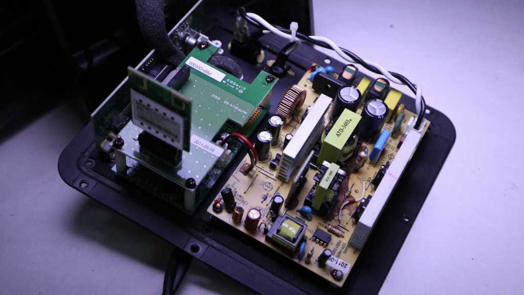
About a year ago I opened up my malfunctioning Insignia 100W Powered Subwoofer (NS-RSW211). I found a burnt-out capacitor, and replaced it with two salvaged capacitors that should work well together. That repair brought the subwoofer back up and running until it fell silent again recently. I looked at the control panel and saw the power LED was dark. Hmm. Back onto the workbench it goes for another round.
The first thing I checked out were the capacitors I previously installed. If there was a flaw in this system that kills capacitors, it might have killed this second set.
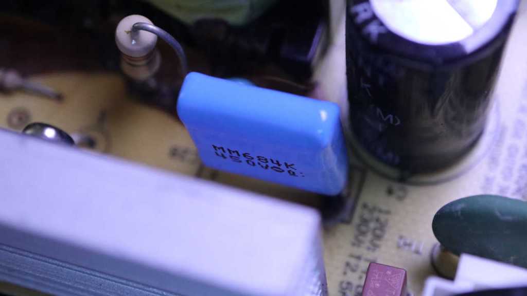
The capacitor up top looks fine
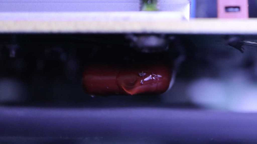
As did its parallel buddy mounted to the bottom. I don’t know if their capacitance has degraded and I don’t feel like unsoldering them to check. For now it is good enough they are not blackened like the original when I found it.
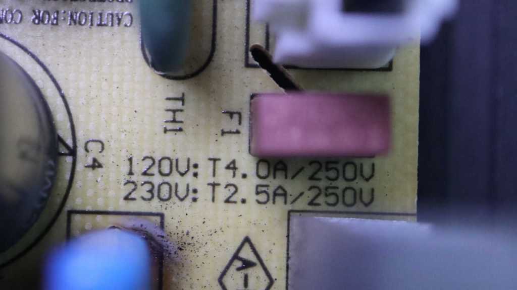
The next thing I checked was the non-user-replaceable fuse sitting adjacent to these capacitors. Electrical continuity checked out OK so it’s not a blown fuse.
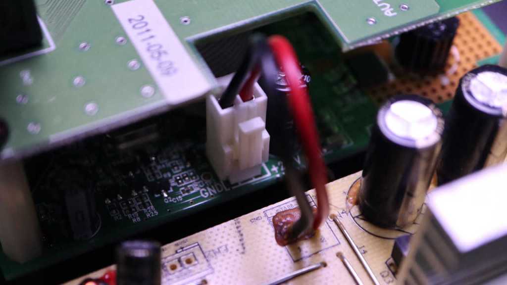
Trying to isolate whether the fault was again in the yellow power supply board, I powered up the system and measured its output connector to the logic board. I read 24V DC, exactly as expected. Implying the fault was not in the power supply board. Onward to the logic boards!
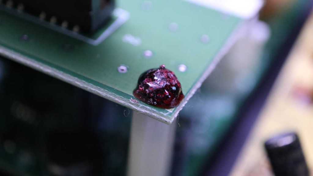
Its top screws had this annoying material on top. I don’t know if this is supposed to be a thread locking compound to keep it from coming loose (a good idea in the vibration environment of a subwoofer) or if it’s supposed to be tamper-resistant. It wasn’t much of a barrier, though, as it is brittle and shatters under light pressure for removal. Maybe it’s meant to be tamper-evident?
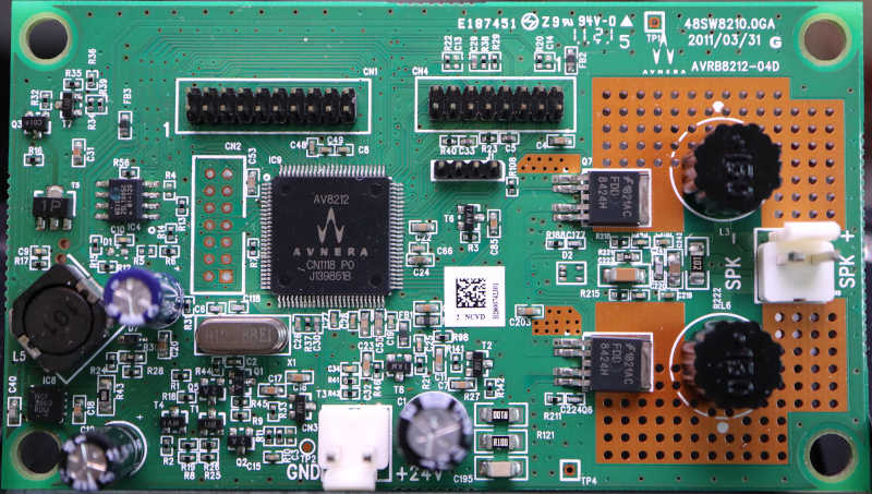
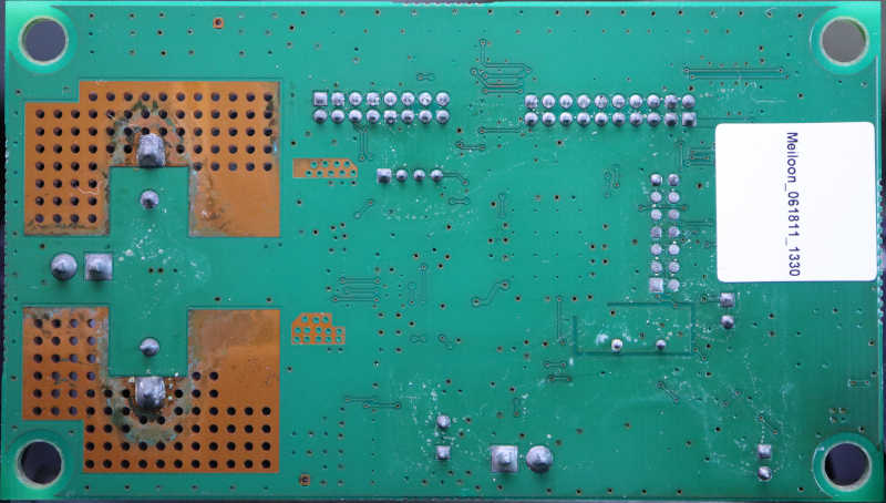
I didn’t notice anything burnt out or visibly damaged on the main logic board, which had an Avnera logo in the upper-right corner as well on the AV8212 controller in the middle the board. Apparently Avnera was the subcontractor for this Insignia (Best Buy house brand) product. Avnera was acquired by Skyworks in 2018 and now every link I’ve found just gets forwarded to the Skyworks home page. Dead end.
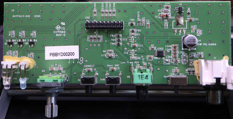
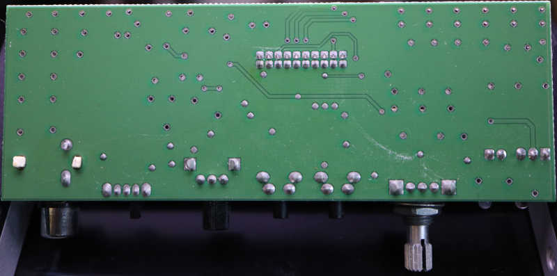
Nothing obviously failed on the I/O board, either. I was surprised to find the volume knob appeared to be a quadrature encoder instead of a potentiometer. From this I inferred the volume could be adjusted via the wireless protocol supported by this device. Something I’ve never used so I never noticed.
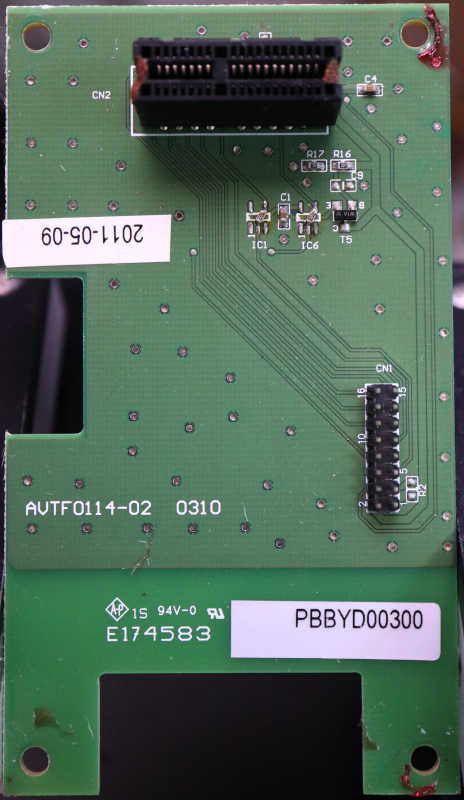
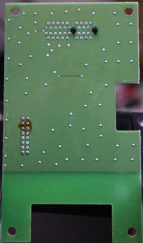
Nothing obviously failed on the wireless carrier board, but then again there’s not much on this board at all. The 16-pin connector is for a ribbon cable to the mainboard, and it is routed almost directly to a connector for the wireless module. It looks like a PCI Express x1 card slot.
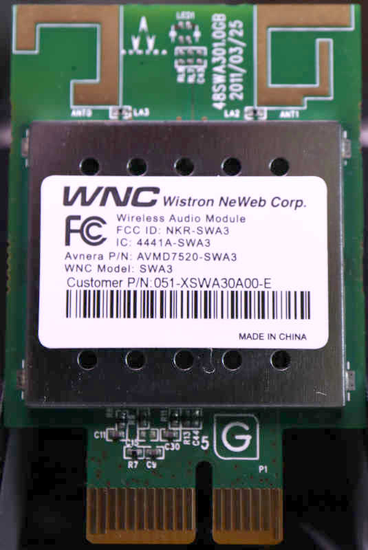
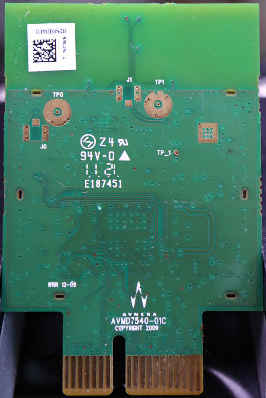
And finally, the wireless module itself. No obvious signs of failure here but most of it is under that metal shield. I see the Avnera logo front and back on the circuit board, but the stick had a different name: Wistron NeWeb Corp. This company has not been acquired by Skyworks, but there were no results for a query on model number SWA3. There’s an Avnera part number AVMD7520-SWA3 but I’ve already established Avnera’s website is gone. That left the FCC ID NKR-SWA3 and that returned some interesting results from FCC’s database. One bit of trivia: they did, in fact, use the PCI Express x1 connector but this is not a PCI Express card.
Sadly I didn’t find any signs of a failure I could fix. Since the 24VDC power supply seems to still be good and the speaker driver itself looks OK, I went online looking for subwoofer amplifier modules. The DC-powered units I found were designed for cars expecting 12V-14.4V and not all the way up to 24V. And regardless of AC or DC power input, everything I found were aimed at powering big booming boxes. Not basic units like this one, so they tend to cost more than just buying another basic little sub. I admit defeat and conclude I’m at the end of the road for this device. Since I had most of the components taken apart already, I continued taking things apart for curiosity’s sake.

Beyond the electronics box, the cabinet was mostly a big box to surround the speaker driver and padded with white fluffy batting.
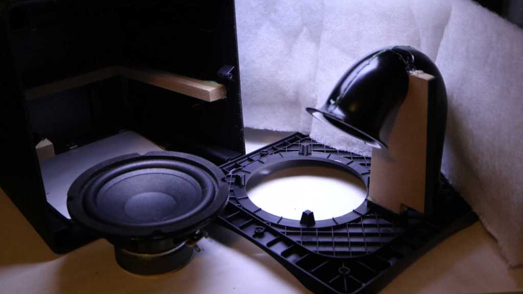
The air duct and port design is interesting, allowing air movement in and out of the subwoofer enclosure. I recognized flared edges exist to reduce hissing airflow noise, but I don’t know the art/science behind the length and shape of the tube. I just think it looks neat! [UPDATE: Thanks to a comment by Nic, I now know this speaker is a bass reflex system and science behind the tube is based on Helmholtz resonance.] Too bad it is glued in place. I’m curious about the few pieces of MDF supporting the injection-molded plastic. What are the respective strengths and weaknesses of these two materials? I thought there was a chance the MDF were late additions to the design to address problems, but they look too well integrated for that. There’s a slot molded in the plastic for the MDF piece supporting the duct.
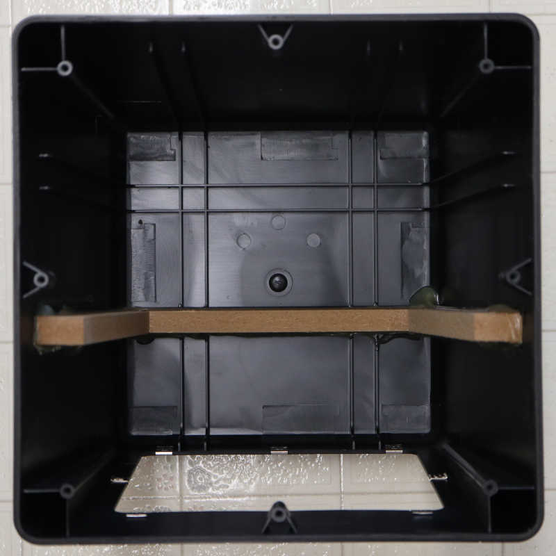
As for the outer enclosure, it looked like multiple slots were molded in place but only one was occupied by a piece of MDF. Perhaps they were reinforcement ribs instead of MDF slots? I can sense some sort of design intent here but I have no guesses on what they were.

Hi there,
The ported sub box tube measurements uses a now readily available algorithmic calculation to produce a length and circumference of the port itself. One must consider the size of speaker to calculate box dimensions, then calculate the resonant frequency of the enclosure, from there; there’s two different lengths of port you can go with. The shortest length, which is what you will find in almost 100% of ported sub box enclosures, aims to simply have the sound that emits from the reverse side of the speaker into the box cause as little disruption (phase cancellation or coloring/comb filtering) to the front side signal as possible when it exits the port – hence all the padding. It ultimately aims to utilize the energy from the reverse side of the speaker to excite as much air as possible, with the port simply acting as the excess energy vent. However, if you were to use the maximum size of the port calculation, it tends to be quite the distance of tubing routed very creatively much like intestines, and will cause the energy from the reverse side speaker fire to travel enough distance that when it exits the tube (note that in this scenario you want the port exiting in as close a proximity to the actual sub as possible) it will combine in phase with the original signal and bolster the energy excitation within the environment in such a manor that much smaller speaker diameters are capable of mimicking very large setups. It’s all actually very, very cool.
And your MDF rib is just for rigidity.
Nic
LikeLike
Awesome info, thanks! Your comment prompted me to go digging for more information. Among my search hits I felt Wikipedia’s “Bass Reflex” page was the most informative.
https://en.wikipedia.org/wiki/Bass_reflex#Explanation
If I understand it correctly, the “readily available algorithmic calculation” you mentioned characterizes the Helmholtz resonance of a subwoofer+enclosure and from that, derive port+tube dimensions.
https://en.wikipedia.org/wiki/Helmholtz_resonance
It’s always great to learn new things. Thank again for the prompt!
LikeLike