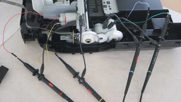
When I started taking apart my old Canon Pixma MX340 multi-function inkjet, I didn’t expect to make heads or tails of the sensor bar. So I was very proud of myself for getting far enough with a reasonable hypothesis on how to work with it, and jotted down some potential approaches potentially scaled down to my skill level. They are potential projects for later. Right now I want to move on with observing other parts of the machine. Today’s subjects: the motors used to move the print carriage horizontally (“X-axis”, in my mind) and a separate but similar motor responsible for feeding sheets of paper (“Y-axis”).
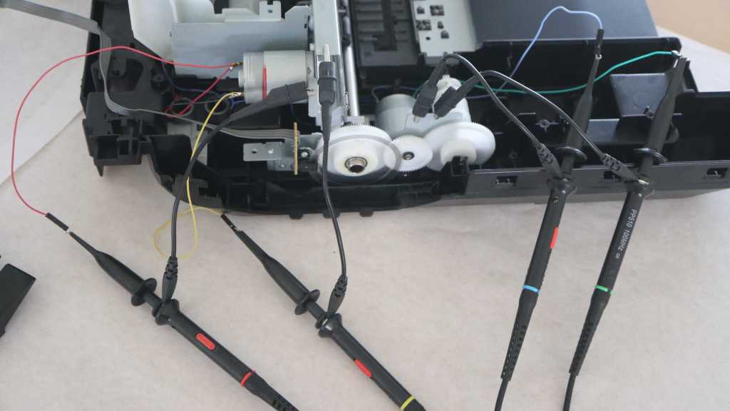
There are two wires on each motor, characteristic of inexpensive commodity brushed DC motors. I was pretty confident I knew what I’ll see on my oscilloscope screen: 0V ground on one wire and 24V DC from the power supply on the other wire in a PWM pattern depending on desired speed. It turns out I was both right and wrong.

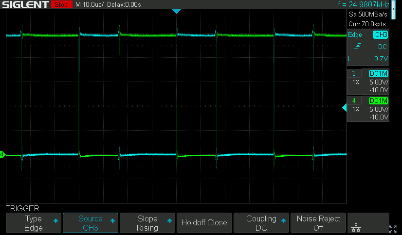
There’s definitely PWM going on, but in both directions! Here’s the oscilloscope plot for the print carriage motor upon startup, moving the print carriage out of its parking spot across the width of the printer. For slow motion I expected a low PWM cycle on one pin and the other pin held kept at ground, but the printer actually alternates between turning the motor forward and reverse with no de-energized states between them. (Not counting the very brief MOSFET ramp-down during the switch.) I guess this is similar to how when we want to make precise motions with our limbs, we keep some tension on muscles on both sides of the joint. The motor speed is thus dictated by the ratio of time spent in each direction.

Continuing the startup sequence: After the print head moved across the entire width of the printer, it moves back towards its parking position at the same speed. Changing the edge trigger channel made it easy to see the same ratio was used except with the polarity reversed.
The paper feed motor is driven in a similar manner. This was also taken during the printer startup sequence, at the moment the motor is spinning in a direction backwards from normal paper feed direction during printing. I don’t know what this motion accomplishes yet, I hope to find out later in this teardown.
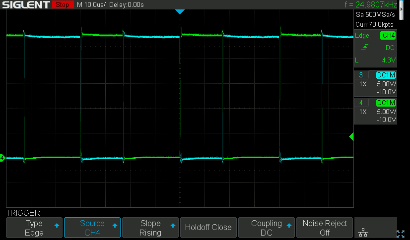
Shortly after that action, the motor turned in the normal paper feed direction for a short distance. (Not far enough to pop open the paper output tray door.) It also turns at a slightly slower speed. The most obvious difference between these two plots are the different in voltage for opposite direction, and a less obvious difference is the power energized ratio between blue and green wires. It is slightly closer to 50/50 when the motor is turning slower.
Driving the motor in this manner is not very energy-inefficient, as most of the power is spent fighting power expended a few microseconds earlier. Only a fraction actually goes into motion, all the rest are turned into heat. Indeed these motors grew warm to the touch after some use. There’s probably an explanation for why this is the preferred approach, somewhere in an electrical engineering motor control theory textbook. Maybe this is the only way to reliably accomplish precise movements with inexpensive DC motors? I should experiment with this concept the next time I revisit my micro Sawppy project, perhaps it would allow the little thing crawl at a more rover-like speed. However, I think it’s likely this motor control scheme only works because it has encoder feedback for a closed-loop control system.
This teardown ran far longer than I originally thought it would. Click here for the starting point.
