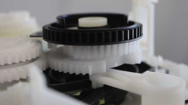
The paper tray in my retired Canon Pixma MX340 multi-function inkjet has a box of mechanisms to orchestrate its page-feeding sequence. Powered by the paper-feed motor, two different actions can be triggered from a gear shifting mechanism by engaging one of two gears. But there was at least one more gear interaction: The forward gear position can be inhibited by another gear, part of the largest assembly in this box.
I didn’t notice this interaction at first, but as I looked at the lever in detail, I noticed a protrusion up top. Given all the design optimizations I’ve seen so far, I knew that protrusion could not have been accidental. I saw it could push against a wall on the big black gear that covered only roughly 240 degrees out of the circumference. This would inhibit engaging the forward gear.

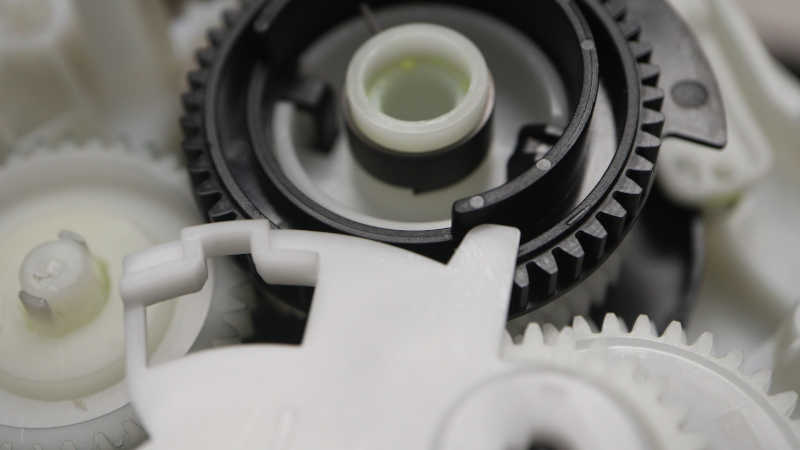
When within that ~120 degree gap, though, it is possible to engage forward gear. I thought it was neat, but as soon as I looked at this big black gear more closely, I realized that was just the beginning. If the black gear continued turning counter-clockwise in this picture, the wall will eventually push on that protrusion and pop it out of gear.
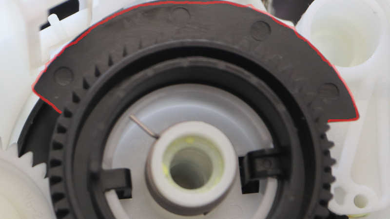
Beyond the ring of gear teeth, I see a thin piece of plastic covering a different ~120 degree arc. This slotted into a photo-interrupter sensor. Looking at the two mechanisms, it appears the beam is interrupted when we’re within the arc where forward gear engagement is allowed.

Which led me to the next question: why would the angle matter in a spinning gear? The answer can be found in layers attached below this big black gear. I saw two white plastic gears, but they didn’t have teeth all the way around. Both are missing teeth (roughly 45-60 degrees worth) at different positions. Adjacent to one side of this gap, 5 gear teeth are mounted on an unsupported arch while remaining gear teeth are mounted rigidly.
I interpret this as a mechanism that can convey motion for part of a rotation before falling into a gap. To re-engage the gears, it would have to turn in the direction of those arch-mounted teeth. Taking advantage of their slight bit of flexibility to help gears mesh back up instead of grinding like a student driver learning a manual transmission car. I never noticed any gear-grinding noises from this machine so I guess it works and reliable enough for years of service.
Attached below the pair of intentionally incomplete gears is another piece of black plastic. A cam mechanism with contours to move arms that actuate mechanisms in the paper tray. The “top” side visible in above picture controls the large spring-loaded flap of the paper tray (labeled “1” below) and the “bottom” side of this cam has two separate contours for manipulating two other mechanisms (“2” and “3”).
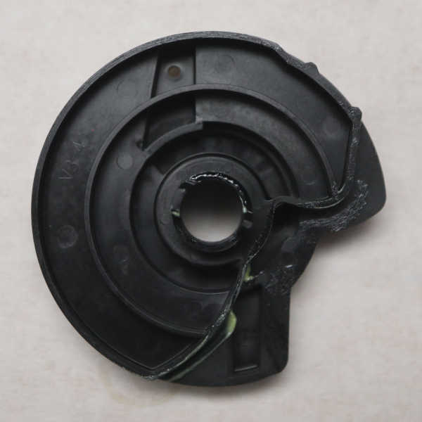
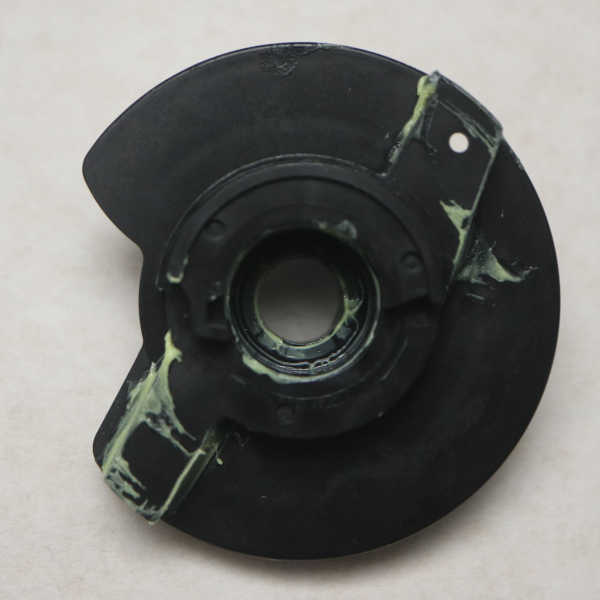
Here are some pictures of the cam by itself.

And a picture of the paper tray. with numbers labeling its moving mechanisms.
All this added up to a lot of mechanical sophistication attached below that big black gear. What I had thought was just another gear in the gear train turned out to be the output shaft for coordinating many separate actions related to feeding a sheet from the paper tray. It even incorporated a freewheel mechanism, something I overlooked at first.
This teardown ran far longer than I originally thought it would. Click here to rewind back to where this adventure started.
