CircuitPython busio.uart Up and Running, Mostly

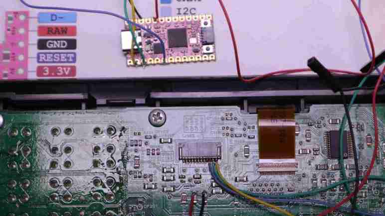
After a quick warm-up exercise of verifying activity over expected serial transmission lines, I updated my code to use CircuitPython’s busio.uart to interpret that activity as asynchronous serial data. Based on earlier analysis, I expect to receive data at least once every 9.2ms, so I set up an asynchronous task to constantly process incoming data. The good news is that I saw a constant stream of 0x80 0x40, which was as expected. I had established 0x80 was the value reported for “no buttons are pressed” so I had expected that value to change if I pressed a button. It did not! Apparently key matrix scan code reporting doesn’t start by default.

In order to parrot the initialization sequence decoded by my logic analyzer, I need to write another asynchronous task. This one transmits given data and then wait for the receiver task to see an 0x20 acknowledgement byte before returning. Once up and running and initialization sequence sent, the receiver task started reporting key matrix scan code values. Success!

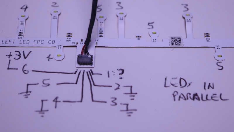
Up until this point I still had the Neopixel sample code running as a system heartbeat indicator. With serial communication up and running, I thought I’d switch over to using one of the LEDs on the control panel. I created another asynchronous task, this one loops to turn the “In Use/Memory” LED on and off at one second intervals while leaving the “WiFi” LED off. I have already decoded the bit flags necessary to toggle LEDs and I got a LED that blinked for a few seconds.

Then it got stuck.

Debugging indicated that my code got stuck because the data transmission to update LED state never received that 0x20 acknowledgement, which meant the transmit task never returned to caller. I quickly whipped up a timeout mechanism by checking timestamp in a loop. It worked, but then I realized there was already a mechanism built into CircuitPython. So I deleted my timestamp checking loop and replaced it with a single call to asyncio.wait_for().

I needed to write this timeout code and retry transmission for robust error recovery no matter the reason, but I want to know the reason why I never got 0x20 acknowledgement. Maybe there are times when the chip is not listening to my commands? Or maybe there’s a problem in my data transmission? I think it’s very likely the chip isn’t always receptive, but that’s not as important as the discovery there was indeed a problem with my data transmission.

CircuitPython countio For Detecting Activity (Limited on RP2040)

I have a rough idea on how I would use CircuitPython’s asyncio capability to structure my learning project, but jumping straight into async/await in a new platform is too bold for me. I would rather ramp up gradually starting with running a few CircuitPython samples. Once I was satisfied my KB2040 board is generally working as expected, I started poking at project-specific needs. First task: see if I’ve soldered serial communication wires correctly by checking for activity on those pins in reaction to enable pin status. (Toggled via CircuitPython’s digitalio module.) I expect activity on the receive pin when the enable pin is high, and no activity when enable is low. The transmit pin should have no activity in both cases.

I had originally intended to check pin status by polling pins in a loop, which is not guaranteed to catch all activity but probably good enough for an “is there activity” check. Polling in a loop would have been trivial in an Arduino test sketch, but CircuitPython made it just as easy to pull in something more sophisticated: countio module counts rising/falling edges driven by hardware interrupts, which would have taken a bit more work to set up on Arduino. Great! Let’s do that.

I copied sample code from documentation and modified it for my purposes of watching pins D0 and D1, which were default UART transmit and receive pins on my KB2040. I saved my file and promptly got an error telling me I am not allowed to do this on D0. Huh? Re-reading countio documentation I saw a paragraph I had missed:

Limitations: On RP2040, Counter uses the PWM peripheral, and is limited to using PWM channel B pins due to hardware restrictions. See the pin assignments for your board to see which pins can be used.

Reviewing KB2040 pinout reference, I see D0 is also PWM0A and D1 is PWM0B. So they are both PWM-capable pins satisfying the first restriction, but only D1 satisfied the second restriction of channel B. Fortunately D1 on PWM0B is the default UART receive pins, so that’s the one I was more interested in checking status for anyway. And the check was good: when enable pin is high, there is a steady stream of activity on D1. When enable pin is low, activity stops. Good enough to take the next step, connect UART peripheral to those pins.

CircuitPython asyncio For Cooperative Multitasking

I want to apply my CircuitPython lessons to a project that will require importing the busio library to utilize asynchronous serial communication hardware on board a RP2040 chip. This is a pretty common microcontroller scenario, but example projects usually only deal with one direction, either just sending or just receiving. Adafruit’s CircuitPython UART serial introduction only received data and did not send. Things will get more complex as I intend to implement bidirectional communication, and even more so because there’s interaction between the two directions: I need to send data and listen for an acknowledgement.

If that’s the only thing being communicated, it would be easy: one line of code to send data, followed by a line of blocking code to wait for response data. But it’s more complicated in this project because the K13988 chip on the control panel sends key scan matrix reports on a regular basis. (Every ~9ms.) If I wrote my code in the naive way, that wait for response may pick up a key scan matrix report byte instead of the acknowledgement byte. What I need is something that is constantly receiving and processing data, mostly key scan report bytes. After the data sender code runs, it will have to wait on the receiver loop to pick out any acknowledgement bytes as they come through in between key scan reports.

This is doable within an Arduino-style loop(), and I’ve done it before, but I end up with code that’s hard to follow as it rapidly switches between multiple contexts. That’s why I was happy to learn CircuitPython implements the async/await pattern with its asyncio library, which should theoretically allow cleaner code structure. My prior experiences with this pattern mostly centered around JavaScript client/server networking code and not microcontrollers, but never fear, as per usual for Adafruit there’s an excellent guide Cooperative Multitasking in CircuitPython with asyncio putting the pattern in context for microcontroller tasks.

It also highlights an important simplifying characteristic of CircuitPython: it has only a single thread of execution running a single event loop, so there is no concern of race conditions between multiple threads/loops and we don’t have to worry about protecting critical sections. Eliminating concurrency eliminates all the huge headaches of writing concurrent code, at the performance cost of running only a single core. A RP2040 has two cores, like an ESP32, but apparently one core sits idle while the other runs CircuitPython. For this project (and most of my potential CircuitPython projects) a single CPU core will suffice. I’m not going to worry about the lack of dual-core operation until I run into an actual problem that needs it. Right now my problems are simple, like checking to see if there’s any activity on a pin.


Installation note: for most CircuitPython libraries in the bundle, we install it by copying its single corresponding *.mpy file into the \lib\ subdirectory on our microcontroller’s CIRCUITPY storage volume. But asyncio is actually a directory containing multiple *.mpy files and we copy the entire directory under \lib\ so all its components are under \lib\asyncio\*.mpy.

CircuitPython busio For Hardware Serial Communication

For my first nontrivial CircuitPython project, I thought I would try getting a microcontroller to communicate with control panel salvaged from a Canon MX340 multi-function inkjet. Like most microcontrollers, the RP2040 chip at the heart of my KB2040 board can handle asynchronous serial communication via its UART hardware peripheral. Under CircuitPython, this peripheral is exposed by an uart class. It is under the umbrella of busio library, which includes hardware-accelerated communication of popular serial buses I2C, SPI, and asynchronous serial. CircuitPython has several libraries with the io suffix, and given their hardware-focused nature they appear to be a big chunk of the work required to port CircuitPython to a new microcontroller.

One aspects of CircuitPython (and MicroPython) I found enticing is the ideal that I could develop and debug code on my desktop computer and then copy it to run on a microcontroller. Unfortunately this goes out the window when I want to use hardware-accelerated features like busio.uart. Its name clearly announces that it is not trying to act like PySerial on the desktop. If I want to write something that works on both desktop Python and microcontroller CircuitPython, I would have to write an abstraction layer restricted to the small subset of common features I need in my project. Learning how to write such adapter code is on my Python learning to-do list, but it is out of scope for my first CircuitPython project. I’ll stick with busio.uart and develop/debug strictly on microcontroller.

One Python skill area I want to improve is structuring my code to better handle non-sequential events. The relevant scenario today is sending serial data out the transmit pin while simultaneously responsive to serial data coming in over the receive pin. Plus handling when the two interact: for example waiting to receive an acknowledgement after sending data. My earlier serial data filtering tool handled reading from two serial ports by rapidly switching between polling the two ports, but in hindsight, that was not elegant code and it didn’t handle interaction between the two streams. In the search for a better way, I recall Python supported the async/await pattern I’ve encountered earlier in JavaScript and C#. Furthermore, CircuitPython supports some form of the pattern as well, so I’m going to give it another go.

CircuitPython Test Run: MX340 Control Panel

After reading through AdaFruit’s “Welcome to CircuitPython” guide, the obvious next step is to tackle a project to apply what I’ve learned. I do want to apply it to a rover project, but I fear that’s too big of a first step. Looking around at what I have, I decided to communicate with the control panel I salvaged out of a Canon Pixma MX340 multi-function inkjet.

During my teardown I mapped out the pinout of its ribbon cable connector to printer logic board. I then connected my logic analyzer (and other tools) to understand its communication to the best of my ability, with findings summarized here. In theory, all I have to do is to use CircuitPython to tell my KB2040 how to replicate what I observed coming from MX340 logic board, and I will have a control panel I can use for a future project. In practice, I’m sure it wouldn’t be quite that easy but hey that’s the fun part!

Examining my deciphered pinout list, I connected the three pins leading to the NEC K13988 chip on board. Asynchronous serial transmit, receive, and the chip enable pin. I also need to supply +3.3V DC logic power and connect ground, but that doesn’t strictly need to be on the small 1.0mm pitch connector. I found a few capacitors that presented a larger surface for soldering my wires. For this first round I won’t bother wiring up the direct connection to two buttons (Power and Stop) and two LEDs (Power and Alarm) as getting those working should be fairly straightforward for a microcontroller project and I don’t foresee any educational challenges there. I can do that after I tackle the more interesting challenge of CircuitPython serial communication.

Notes on Adafruit “Welcome to CircuitPython”

After getting comfortable with the idea of learning CircuitPython, I began reading Adafruit’s Welcome to CircuitPython starting guide. I found this to be a great introduction and met my expectation for a document helping beginners get started with CircuitPython. That said, my opinion isn’t as good as one coming from an actual beginner! They would be the true test whether Adafruit succeeded.

[UPDATE: I just noticed that there is a lot of overlap between the general welcome guide and information posted under the KB2040 umbrella. However, they’re not identical. The KB2040-specific version had no reason to cover CircuitPython Hardware, and the general version lacked some sections like CircuitPython Pins and Modules.]

The most immediate interface point of CircuitPython is that it shows up as a USB file storage device. We just have to put our code in a file named code.py on the device, and every time we save our changes they will immediately run. This architecture means any device that can edit files on a USB flash drive can be a CircuitPython development tool, and feedback is immediate for instant gratification. This is great for beginner-friendliness! But I’m a grumpy old man set in my ways. I like keeping my source code in a git repository and that means I have to copy my file from my repository to the USB drive. This is probably not a deal breaker and I expect to find a workflow that will work for me, but it did start me on the wrong foot.

While any text editor will work, Adafruit does name Mu as their recommended Python code editor. Advertising itself as a simple Python editor for beginner programmers I thought I would use it at least for the duration of my learning on-ramp. I found it to be a simple straightforward Python editor, supporting not just CircuitPython but also MicroPython and just regular ol’ Python on computers. It felt a bit like what Visual Studio Code used to be, before it got all bloated with features. Notably, Mu is not so overly simple that it became infuriating for me to use, which makes it better than Arduino IDE before version 2.0.

Speaking of Arduino IDE idiosyncrasies, I like the fact CircuitPython handles libraries for a project by putting them in a \lib\ subdirectory. I felt this was more straightforward than Arduino’s package manager, which always felt more complicated than it needed to be and weighed down by a massive catalog of community contributions.

In comparison, CircuitPython doesn’t have as long of a history to build up such a huge library, but Adafruit & contributors have been making great effort covering common needs. Every time I thought of something I might need from a library, a search quickly found one. (The latest: rotaryio to handle quadrature encoders.) So far, so good! What I need now is a learning project putting CircuitPython to work for me.

MicroPython And CircuitPython Are More Alike Than Different

I want to learn how to work with RP2040-based microcontrollers, and I like the idea of working in a high-level language like Python. Or at least, I would like to give it a shot. Reading about Python for microcontrollers quickly run into two names: MicroPython and CircuitPython. Looking around for information on why I might choose one or the other, I found a wonderful comparison guide published by Adafruit. Based on this information, I now feel more comfortable starting with CircuitPython.

For me, the most important piece of background is that CircuitPython is built as a fork of MicroPython, with enhancements focused on beginner friendliness (an Adafruit signature) versus full support for all features. For someone learning to blink a LED, CircuitPython aims to be the best solution. Beyond the basics, intermediate level projects (where I feel I fit) are likely to be served equally well by either platform. Advanced features like threading and PIO are where CircuitPython concedes to MicroPython, but speaking for myself I won’t have to worry about that for a while if ever. And even if I find myself in a situation where I need to switch, I’m comforted by the claim 95% of knowledge will transfer directly between the two platforms.

What will likely swing the decision for most people are software modules they want to pull into their project. And here I think CircuitPython will take the lead for my scenarios. I buy a lot of stuff from Adafruit, and they are likely to provide CircuitPython libraries for those components. So that covers a lot of hardware which also serves as example code to learn from if certain hardware is not explicitly supported. And following my earlier search for a MicroPython web server with WebSocket support, I found that CircuitPython offers a counterpart httpserver which should be sufficient for my rover project purposes. Looks good enough for me to dive on in.

Dusting Off Adafruit KB2040

My latest distraction is a Raspberry Pi Pico W, a promising alternative to ESP32 for a WiFi-capable microcontroller board. After a cursory experiment with a single LED, I’m ready to connect more components to the board to explore its capabilities. Since it’s new hardware, though, there’s always the chance I’ll goof up somewhere and destroy the microcontroller. I don’t want to take that risk because I’m borrowing this particular Pico W. It’s not mine to blow up! Thinking over my options, I remembered that I already had microcontrollers built around the same RP2040 chip: a pair of Adafruit KB2040.

I got my KB2040 as an Adafruit promotion. They typically have something set up to entice us to put a few more items in our shopping cart, and these were “Free KB2040 with $X dollar purchase” type of deal I got across two separate purchases. As the product page made clear, KB2040 was designed for people building their own custom keyboards. So it was built to be physically compatible with an existing board (Pro Micro) popular with that niche. I had no intention of building my own custom keyboard, but I thought the RP2040 chip was worth a look at some point in the future. That time is now.

There are a few tradeoffs of using a KB2040 to substitute a Pico W. The first and most obvious problem is the fact KB2040 doesn’t have the WiFi/Bluetooth chip, so I could only practice aspects of programming a RP2040 before I bring in wireless connectivity. Equally obvious is the different physical form factor, which means a different pinout. I didn’t think that was a huge deal because I’m not trying to install the board on anything that expects a specific pinout. I printed Adafruit’s pinout reference chart and I thought I was good to go, but I wasn’t. While the RP2040 chip lies at the heart of both a Pico W and a KB2040, they have different peripheral chips. This means I’d need a KB2040-specific build of software and it is not on MicroPython’s list of supported Adafruit boards. D’oh! Fortunately, Adafruit supports KB2040 for CircuitPython. Is it close enough for my purposes? I now have motivation to find out.

HP Windows Mixed Reality Salvaged LED Pinout

While doing a bit of work bench clean up, I found the LED arrays I had intended to salvage from my HP Windows Mixed Reality headset teardown. The surface mount LEDs were soldered on flexible circuit boards so they’re a bit too fragile for me to just toss them in a plastic bag. I found a piece of cardboard to serve as a backing and that should help. Before I put them away folded between sheets of cardboard, I thought I’d pull out my LED tester. Here’s what I found out about their pinout, in the hopes such information will be helpful for future project planning.

The two long strips came from handheld controller location beacon rings. Their shapes are symmetrically mirrored between left and right hand controllers, but they both use the same electrical connector. I saw a small arrow and decided that was pin 1, but it didn’t seem to connect to anything? Pin 6 is the common positive power supply, and pins 2 through 5 are grounds, one for each of four strings. Each string of LEDs are wired in parallel, so 3V is enough to start illuminating them with 20mA shared across all LEDs. There are resistors visible on board so current limiting seems to already exist if I’m ready to crank up the voltage. The LEDs are labeled D1 through D32. I had guessed these 32 LEDs would be evenly divided among 4 strings for 8 LEDs each, but it’s actually two strings of 7 and two strings of 9.

Connector Pin#LED StartLED EndLED Count
2D26D327
3D19D257
4D10D189
5D1D99

Using my mini hot plate I also salvaged the cable PCB connectors. I don’t know if I will use them, but I have the option to do so if I want. At the moment I’m not sure how I might utilize these two very irregularly shaped string of LEDs.

The two short strips came from visor LCD backlights. I wanted to keep the entire backlight display but it was so thin and delicate I failed to disassemble them intact. These LED strips are my consolation prize. Two identical units, one for each eye. Four pins on the connector for two LED strings, but again they are not equally sized. The inner pair powers a string of 6 white LEDs in series, around 17.1V DC for 20mA. The outer pair powers a string of 7 white LEDs in series, around 19.9V for 20mA. I don’t see current limiting resistors here so something else will have to keep things under control.

I thought about using my hot plate to pull these connectors from the flex circuit board as well, but decided to use scissors to cut off most of the flex circuit board and keep the connectors attached. I think this pair of ex-backlight LEDs will work well as PCB side lights, once I can think of a good design for a light-up PCB holder.

Instant Print Toy Camera

A few months ago I learned of digital cameras with integrated thermal printer for instant photo printing. As toy cameras aimed at kids, they have colorful exterior and low price to match. I decided it would be fun to get one. Play with the novelty for a while, then take it apart to learn its electronic guts. Perhaps it can be modified to satisfy one of my friend Emily’s suggestions for my Sawppy rover: instead of a robot arm with scientific instruments, maybe I can build a robot arm with a selfie camera. And with this design, I can instantly print the photo to share!

There are multiple vendors selling different implementations of the same basic concept. I decided on this particular unit (*) for two reasons. First, because it was the cheapest offering of the day and second, it has a camera sensor that can swivel 180 degrees to switch between front-facing (normal use) and back-facing (selfies). The swivel implies a long flex cable, and that should make rover integration easier.

(Picture of toy camera taken by serious camera.)

A lot of accessories came bundled inside the box. Starting with five rolls of thermal paper to feed lots of prints. A pack of color markers let us perform colorization by hand, and a USB type A to type C cable for charging its internal rechargeable battery. Even a neck strap was included!

The camera enclosure was surprisingly well built. I had expected a few simple piece of ill-fitting injection-molded plastic, but it turned out to be more sophisticated than that. The eyes are separately molded pieces of white plastic instead of the sticker I had expected from product listing pictures. The ears are likewise separate pieces, as they are molded in a soft material. No weird plastic flashing and all pieces fit together well. This is pretty amazing quality considering the price point. I’ve paid more for stuff from Harbor Freight that weren’t made as well as this camera. I will be sad to break open the case later, but not enough to dissuade me from my original plan.

I got this device for its instant-print photo capability, but it can also record videos and there’s even a “Hungry” game that’s a weak implementation of the immortal snake game. It reminded me that, as primitive as the screen may be by modern standards, it is generations ahead of the black-and-white LCD used in classic Nokia brick phones.

(Picture of toy camera accessories taken with toy camera then printed by toy camera. Then the serious camera was used to take this picture of the print.)

Photo image quality and print quality were about as expected, which is to say quite poor and appropriate for an inexpensive toy. Certainly Canon won’t lose any sleep over this thing. But it’s definitely good enough to tell what the picture is supposed to be, and its unashamed low fidelity has an unique charm of its own. Given the price point I really can’t complain.

After playing with it for a few hours, print contrast was noticeably faded compared with earlier prints. I first thought maybe the device was designed fully expecting kids to get bored and lose interest quickly, and thus designed with a short service life in mind. But that’s inconsistent with bundling five rolls of paper! It then occurred to me I should try recharging the battery, and that turned out to be the answer: a topped off battery restored the full (if not very wide) range of contrast. Print quality a direct function of battery voltage? Wow. This thing is so spectacularly simplistic it has become its own special kind of awesome. It’s fun, I like it!


(*) Disclosure: As an Amazon Associate I earn from qualifying purchases.

Search For Pico W Web Server Led To MicroWebSrv2

One of the bare minimalist examples I saw while readingConnecting to the Internet with Raspberry Pi Pico W” was a simple HTTP web server. It only serves a single page which is represented by a string embedded in the source code. This is obviously not going to work for anything serious.

Fortunately, the popularity of ESP8266 and ESP32 pioneered an ecosystem of web servers suitable for running on microcontrollers. Many of which have already been adapted to run on the Pico W, as the new hotness on the block. They all meet the primary requirement: Serving static files on board microcontroller flash storage, rather than strings embedded in source code. This is important because I want to update them without having to touch my web server files, and second because I don’t want to hassle with string escape and other inconveniences of embedding HTML/CSS/JS syntax inside valid C or Python syntax.

Most of these web server options were written in Arduino or another C-based framework like ESP-IDF, but a few of them were written in MicroPython so I thought I would look at those first. Beyond serving static files, many of them have routing and associated mechanisms for dynamic server-side responses. Several such frameworks said they’re modeled after Flask, which I’ve played with before, and makes sense in a Python context.

But the one feature I would like is web socket support. I want to try porting my micro Sawppy interface to such a system and that uses web sockets to communicate between the cell phone browser acting as remote control and the microcontroller driving my mini rover. This surprisingly eliminated almost all of the candidates. I found only MicroWebSrv2 for MicroPython compatible web server framework with web socket support.

I am intrigued after a cursory glance over MicroWebSrv 2 README. Especially the claim that MicroWebSrv2 can run on desktop computer Python as well as microcontroller MicroPython. In my earlier development efforts for micro Sawppy interface, I wrote the server-side code twice. Once in NodeJS (JavaScript) as a stub to help me develop on the desktop, and again in ESP-IDF to run on an ESP32. It would be great if I can have a single chunk of Python code that handles both cases. I have to review my code to see what other support infrastructure I would need. The first one off the top of my head is a JSON parsing library, which is included in MicroPython, a good start.

Notes on “Connecting to the Internet with Raspberry Pi Pico W” eBook

After getting my bearings with the “Raspberry Pi Pico Python SDK” eBook, I checked out the Pico W-specific “Connecting to the Internet with Raspberry Pi Pico W“. This volume is even smaller at 49 pages, fitting for an quick introduction to potential of Pico W connectivity. It felt to me like the word “Connecting” in the title is quite literal: this title covers how to establish a connection and not much else on what to do after you connect. Perhaps the authors believed that networking APIs are common with existing platforms. So maybe once we get a Pico W set up enough to connect, everything else will be the same as existing general resources out on the internet? That seems unlikely but maybe a valid stance for an introductory title.

But while the word “Connecting” might be literal, the word “Internet” is not. This book actually goes beyond Pico W’s WiFi connectivity and also covers its Bluetooth LE capability. BLE is not typically used to connect to the internet. It appears the Pico W is also capable of Classic Bluetooth, but this book doesn’t spend much time on that beyond mentioning it was possible.

This book also covers each concept twice: once with the C/C++ SDK, then again with the MicroPython SDK. Seeing them side by side really brought home the fact MicroPython code is generally easier to read. But sadly, the language can only do so much. Bluetooth LE is full of esoteric overhead that needs to be configured no matter the language. An uninformative barrier against beginners trying to learn the technology. While reading one particular example’s MicroPython code in the PDF, I got tired trying to parse BLE minutiae and it occurred to me… I don’t remember reading anything equally dry in the C section. I scrolled back up and that’s when I realized the book authors gave up: there was no C section. Instead of cluttering the book with a bunch of code dealing with C overhead plus BLE overhead, they just said the example code is on their GitHub repository. With a URL for the C developers who care to go wading through it all.

This book tried to cover WiFi, Bluetooth Classic, and Bluetooth LE connectivity enabled by a Pico W over its non-W counterpart. And cover those topics via both C and MicroPython languages. That’s a lot of ground to cover in 49 pages, resulting in a book that feels more like a Getting Started pamphlet. Which is a valuable resource! It was just less than what I had hoped.

Notes on “Raspberry Pi Pico Python SDK” eBook

I’m playing with a borrowed Raspberry Pi Pico W, and thought I’d play with MicroPython on it. That software platform seems to have support direct from Raspberry Pi, which is always promising. I thought perhaps it might even get equal billing with the traditional C-based platform! Well, as soon as I opened up Raspberry Pi Pico Python SDK ebook I knew they were not equal. Despite the usual warning not to judge a book by its cover or length, the fact is there are 54 pages in the Python SDK ebook which is barely 10% of its counterpart C SDK ebook‘s 523 pages.

But I don’t necessarily see that as a bad thing. The advantage of a smaller book is that it’s easier for people to read through and absorb, which aligns with the goal of having Python on a microcontroller to begin with. The book frequently refers the reader to the C book for details not specific to the language, such as details on working with the programmable input/output (PIO) blocks. Writing PIO code is little different from writing in assembly language, and a challenge I intend to tackle sometime in the future.

I was happy to see the prebuilt MicroPython distribution binary for Raspberry Pi Pico W was generated by MicroPython organization, instead of a separate fork maintained by Raspberry Pi. This should mean features are introduced in step with the rest of the MicroPython ecosystem and not lagging behind waiting for someone else to integrate upstream changes.

Another item I was happy to see was a Visual Studio Code extension to ease working with MicroPython. MicroPico, formerly Pico-W-Go, promises a lot of convenience over using a serial terminal like PuTTY, which was what I did before. I’ve become familiar with VSCode so I’ll use the extension first, but people without such affinity have other options like the popular Python IDE “Thonny” and a command-line based “rshell” tool that should be useful for scripting.

Trying MicroPython Again This Time On Raspberry Pi Pico W

I’ve borrowed a Raspberry Pi Pico W for experimentation. I’ve verified it could easily integrate into Home Assistant via ESPHome. (Which is now somewhat misnamed as it works for more than just Espressif ESP chips…) For my next set of Pico W experiments I decided to give MicroPython another try. I tried MicroPython earlier on an ESP8266 and it was not all smooth sailing. Looking for an existing solution to my problem was actually the reason I stopped my MicroPython experiment and found Home Assistant and ESPHome! So this is sort of coming full circle.

The main reason I wanted to give MicroPython another try was the fact Raspberry Pi foundation listed C and MicroPython SDKs side by side as software development platforms for Pico and Pico W boards. This implies MicroPython is treated as a first-class citizen and supported directly from the source. Will actual reality live up to this implication? I don’t know yet but I’m willing to find out. This is also why I’m trying MicroPython before investigating Adafruit’s CircuitPython for the board. As much as I love Adafruit, direct manufacturer support is very compelling.

The obvious criticism of MicroPython is runtime performance. I will have to see how much of a problem it would actually cause for my projects. I’m cautiously optimistic runtime performance will not be a hindrance for two reasons. One, hardware peripherals can handle most performance-critical tasks asked of a microcontroller, and that will largely be the same whether overarching high level application code is in C or in MicroPython. What if there isn’t an applicable hardware peripheral on the RP2040 chip? That leads to the second reason: RP2040’s programmable input-output (PIO) capability. Proven to be adept handling tasks that would otherwise need to be written in low-level interrupt handler code, if it can be implemented that way at all. Sounds like a potentially fun playground to see if reality lives up to theory. I’ll start with the PDF published by Raspberry Pi to guide curious Python developers to Pico W.

Easy To Get ESPHome On Pi Pico W

After borrowing a Raspberry Pi Pico W board to play with, I had many ideas I wanted to try out. The first test was Home Assistant support via ESPHome, and this was a success. In fact, I think getting ESPHome started on a Pico W is even easier than doing the same on their namesake Espressif boards.

A tremendously useful feature of ESPHome is the ability to perform updates over WiFi. This over-the-air (OTA) capability means every ESPHome-powered node in a Home Assistant network can be updated wherever they are around the house, no need to bring them back to a computer with a USB cable (or bring a laptop with USB cable out to them). However, this only works after ESPHome is already running on board, which means initial ESPHome setup on a microcontroller still require a USB connection to install a compiled binary file.

For ESP8266 and ESP32 board, this means connecting it directly to the computer running Home Assistant which can get complicated depending on how Home Assistant is set up and whether its ESPHome plug-in can access USB ports. Alternatively, it can be installed by an ESPHome web tool. Or we can install Espressif’s esptool flash utility on a computer. So this is a solvable problem.

But a Pico W has an even easier way: do it on any modern computer, no software installation required. Because when we hold down the “BOOTSEL” button upon powerup, the Pico W presents itself as a generic USB storage device, to which we can copy the compiled binary file (it has a *.uf2 extension) and the Pico W is off and running. Very nice!

As is typical microcontroller practice, my “Hello World” is to connect a LED to my Pico W and toggle it on/off from Home Assistant. I saw an onboard LED, labeled GPIO25 on a pinout chart, and thought I would use that. When that didn’t work, I looked closer and realized I had mistakenly referenced the pinout chart for a Pico (not W) and Pico W’s onboard LED is actually connected to its WiFi chip instead of 25. Oops! It’s not clear to me where pin 25 was routed on a Pico W, so I switched gears: I connected an external LED with current-limiting resistor to pin 15. And since the board was already running ESPHome firmware, I could do an OTA update to use pin 15 instead.

New Toy: Raspberry Pi Pico W

For the past few years, an ESP32 has been my microcontroller of choice for wireless network-connected projects. Its extensive list of hardware peripherals attract attention from those curious what they can do with such a flexible tool, so now we enjoy a huge online community providing reference support for hobbyist projects like mine. It’s a good situation! People have managed to do some pretty amazing things with ESP32 peripherals, pushing them beyond their original design intent. Espressif has been riding the wave, releasing many chips under the ESP32 umbrella with different peripherals and sometimes even different core CPU architecture. (RISC-V in addition to Tensilica.) To maintain software compatibility throughout their product line, they kept a single SDK (ESP-IDF) for all their different ESP32 variations. Unfortunately, maintaining that commonality meant certain wild features had to be deprecated or removed because they would work on some chips but not others. This has the side effect of crippling certain creative off-the-beaten-path hacks.

With confusion rising between ESP32 variations and restricted/deprecated ESP-IDF features, people started looking at alternatives. While discussing ESP32 projects with a few other local makers, the topic switched to one of the new hotness: Pico and its WiFi capable counterpart Pico W by the Raspberry Pi foundation. In addition to a lot of good (if relatively standard) features, it has a novel feature of programmable input-output (PIO) state machines. I understand it as way to create custom digital logic at a lower level than C code running on the main CPU but at a higher level than FPGAs. I’ve read about some pretty interesting ways people have applied PIO to solve problems otherwise tricky to do on a microcontroller.

I agreed that a Pico W sounded interesting to investigate at some point, and one of the people present offered to lend me one they are not currently using. Well, it’s tough to turn down such an opportunity! With a unit in hand, learning how to work with this microcontroller has been vaulted to the top of my project to-do list. My first test: connect it to my Home Assistant.

I Need More Practice with CadQuery Coordinate Spaces

I thought I might design and 3D-print something to repurpose components salvaged from a disassembled Harbor Freight mini LED flashlight. I still might do that, but another thought occurred to me: for the purpose of CadQuery practice, I don’t need to invent something new, I can try to model the salvaged components themselves.

So I pulled out my calipers and started taking down dimensions for the front window, shiny reflector module, and the circuit board hosting the array of nine LEDs. The front window is trivial, a single flat cylinder, but it got more complex from there.

The good news is that, despite some worrisome early signs, CadQuery has proven to give me better feedback on my mistakes than FreeCAD has. Especially from code centric aspect of Python syntax errors because that gives me a line number of the problem. CQ-Editor also gives a very code centric capability to step through my CadQuery design line by line, which makes debugging much easier than trying to understand where I went wrong in a FreeCAD design.

The bad news is that I have yet to build a mental understanding of how CadQuery coordinate spaces work. I’m frequently confused by parts popping up at positions or orientations different than where I had expected. For some of these mistakes I could see my misunderstanding after the fact, for other mistakes I still don’t understand where I went wrong.

    p = cq.Workplane("XZ")
    p = p.polygon(8,led_ring_diameter, forConstruction=True)
    p = p.vertices()
    p = p.eachpoint(
        lambda pos: (
            ring.add(
                make_led(),
                loc = pos,
                color = color_clear_plastic
                )
            )
        )

In this code snippet, I am working on the XZ plane and I drew a construction octagon on this plane. I then placed an LED at each vertex of that octagon, but they were position on the XY plane instead of the XZ plane.

Why did this happen? I have yet to figure out the root cause. So far I only have a workaround: insert extraneous intermediate CadQuery assemblies for the sake of rotating parts to where I had expected them. I know it isn’t the right tool for the job, but I appreciate CadQuery giving me such tools to bludgeon my way to an imperfect but acceptable state. This is much preferred over FreeCAD’s unhelpful “recompute failed!” leaving me staring at the screen with no recourse.

Waking Up Neglected Scooter Battery Pack

One of my long standing to-do list items is to understand and master control of brushless DC motors. My goal is small robots, so I want to work with motors bigger than tiny multirotor aircraft motors and smaller than beefy electric car motors. Towards the upper range of my interest (before their voltage/amperage start to get scary) are motors used in two-wheeled balance scooters. As a Back to the Future fan, I am offended these devices have been marketed under the name “hoverboard” but that is out of my control.

I’ve been waiting for their prices to drop and they seemed to have settled near the $100 mark. When my local Target advertised a sale dropping a “Jetson Rogue” below $100, I got one with the intent of taking it apart to see what’s inside. But I have yet to do so and it has since gathered a thick layer of dust. It occurred to me I should charge up the battery occasionally. I plugged in the charger and… nothing. Hmm. Not good.

Opening it up, I found its battery pack had a single commodity XT60 connector and nothing else. I can work with that.

I’m mildly concerned by the fact this device had wires that didn’t go anywhere. This white wire has a crimped metal end but it’s not part of any connector I could find.

This properly crimped connector is likewise missing anything to plug into.

Those are mysteries to be solved later. Right now I want to see if the battery is dead or if it can be revived. I unplugged the XT60 connector and measured approximately 3V across its terminals. This is low even for a single cell. The label said it was a 7S2P battery pack with a nominal voltage of 25.9V so yeah, I had waited too long to keep it properly charged. Over-discharging is bad, but it is not necessarily fatal.

I set my bench power supply to deliver up to the full 29.4V appropriate for seven lithium-ion cells in series, but limited to a current of 50 mA. This is 5% of the rate delivered by its charging power adapter and should be very gentle on the battery cells in their delicate over-discharged state. I connected the battery, and my power supply control panel showed power delivery was jumping around. 8V for a second, then no power draw at all for several seconds. Then 9V for a second, and things cut out again. This was unexpected. I disconnected my power supply to investigate further.

Thankfully this battery pack enclosure was held together with screws, so I could open it up for a look inside. Aha! It is not a raw package of 14 cells in 7S2P configuration, they are under care of a battery management system (BMS) board. Similar to the 3S BMS board I had played with, but this one handles 7S cells. There are spot-welded tabs to monitor voltage of each 2P group. Some of those spot welds are… not textbook, let’s say. But they have continuity and they let me measure voltage. The situation looks even better here. Each 2P group (B- to B1, B1 to B2, etc. through B6 to B+) ranged from 1.1V to 1.9V. The pack as a whole is actually hovering around 10V across its “B+” and “B-” terminals. This is still over-discharged but in far better shape than 3V I measured across output terminals. (P+ and P-)

While the BMS chip is designed to allow charging across P+ and P- terminals, a over-discharged battery is outside of its normal operating range. For reasons I don’t understand, this chip is cutting in and out as I tried to charge with gentle low amperage. The chip may be taking deliberate action to work with over-discharged cells, but it may be getting confused by either the low voltage or my low amperage. There’s a chance the chip’s algorithm is confused and is on a path to destroy itself, the battery cells, or both.

I decided not to trust the chip and go with what I know: steady charge at a gentle low rate. With the pack open, I could connect my bench power supply directly to B+ and B- terminals. This bypassed the BMS chip and allowed me to slowly bring up voltage across the whole pack. Many hours later, pack voltage was up to its nominal 25.9V and I disconnected my power supply. I left the pack sitting overnight so internal chemistries can take its time balancing everything out. It was left outdoors in a bucket, just in case the chemistry decided to get angry. The next day I was happy to see it did not burst into flames. I put it back into the scooter. Now the scooter was willing to power up, and was also willing to take power from its charging adapter. I think we are back in business.

CadQuery Definitely Under Active Development

CadQuery is definitely under active development, with a long to-do list they still want to tackle. For a beginner, it can be occasionally disorienting learning a moving target. Generally speaking it’s better to have an active and evolving project rather than relying on something that has been abandoned, but it’s definitely a double-edged sword.

On the upside, new features are being added. Reading through documentation I noticed a new section “Free function API” just popped up. That page doesn’t explain exactly why someone would or would not use this new API. Or at least, if it did the explanation didn’t make sense to this beginner.

And on the downside, sometimes things break. I am still learning the basics of CadQuery assemblies, so I noticed the assembly constraint solver demonstrations have gone out of whack. What used to be a nicely laid out door with doorway built of aluminum enclosures is now a jumbled arrangement of parts.

I copy/pasted the example code into my copy of cq-editor and it looks OK. I wonder if a newer build of cq-editor would mirror this regression. Whatever generated this documentation page certainly had some sort of problem I don’t understand.

There’s one upside to this bug: it told me these aren’t static screenshot images. And I thought “I wonder if these are actual 3D viewer controls” and they are! I could click inside the area and change my viewpoint. There were no visible controls or anything giving me a hint this might have been the case, until I noticed the error.

I looked on CadQuery issues database and didn’t see anything that directly mentions this problem, so I opened issue #1585. We’ll see where this goes. [UPDATE: the developers found an angle unit degree/radian mixup in conversion to JSON, a code path used by sphinx-doc interface to generate documentation. The bug was inadvertently introduced alongside free function API, and the bug has been fixed.]

Harbor Freight Mini LED Flashlight Teardown

I want to learn CadQuery to see if I can use it for my 3D printing projects, but at the moment I’m drawing a blank for a good project to climb the learning curve with. I looked over my teardown queue for potential inspiration and decided to take apart a Harbor Freight mini LED flashlight. This was one of the items they used to give away “Free with Purchase” to entice people like me to stop in, so it must have been made cheaply even by Harbor Freight standards. A good item to compare & contrast with an earlier giveaway keychain LED teardown.

The push button switch at the end unscrews to release a battery tray holding three AAA batteries. Given Harbor Freight price points, it’s not a surprise these batteries inevitably leak and destroy the device. I have several of these little flashlights and I picked this one as it had yet to corrode. The trio of batteries were wired in series, for a theoretical maximum of 3 * 1.5V = 4.5V.

I found no fasteners on the head of the device, nor any signs of glue, so it might be held together by friction alone. I pulled out my pliers and the thin metal construction could be peeled apart. It seems to be roughly the thickness of a food can, but peels much more easily, so probably aluminum instead of steel.

After unrolling that lip, I could remove the clear plastic cover, the shiny plastic reflector, and a circuit board with nine 5mm white LEDs soldered in parallel. There were no signs of a current-limiting resistor, so this design must have been dependent on cheap alkaline AAA battery internal resistance to keep this thing from burning itself up.

Connected to my bench power supply, I gradually dialed up the voltage delivered to this array of nine LEDs. At just under 3.3V, the power supply reported supplying 9 * 20mA = 180mA of current. I guess three cheap alkaline AAAs asked to supply 180mA would sag to 3.3V or less. Either that or the designer of this cost-optimized design decided they don’t care if these LEDs burn out.