Adafruit Memento + AMG8833 Overlay: Performance Timers

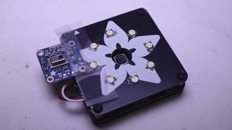
I’ve successfully overlaid data from a AMG8833 thermal sensor on top of the Adafruit Memento camera viewfinder, turning it into a thermal camera. A very slow and sluggish thermal camera! Because my first draft was not written with performance in mind. To speed things up, I converted my thermal overlay to use TileGrid and take advantage of the compositing engine in Adafruit’s displayio library. In theory that should have been faster, but my attempt was not and I didn’t know how to debug it. I went looking for another approach and found MicroPython/CircuitPython has ported a subset of the powerful Python NumPy library as ulab.numpy. And furthermore, there was an example of using this library to interpolate AGM8833 8×8 data to a 15×15 grid in Adafruit learning guide Improved AMG8833 PyGamer Thermal Camera. Ah, this will do nicely.

Add Performance Timers

The first thing I got from that project is a reminder of an old lesson: I need to record timestamps during my processing so I know which part is slow. Otherwise I’m left with vague things like “TileGrid didn’t seem much faster”. I added several lines of code that recorded time.monotonic_ns() and a single line at the end of my loop that print() delta between those timestamps. Since the units are nanoseconds and these are slow operations, I get some very large numbers that were unwieldy to read. Instead of dividing these numbers by 1000, I right-shifted them by 10 bits to result in a division by 1024. The difference between “roughly microseconds” and “exactly microseconds” is not important right now and, in the spirit of performance, should be much faster.

Measure TileGrid Implementation

Here’s are four frames from my TileGrid implementation:

read 38087 scaled 3099 mapped 1789 grid 1728 blit 28223 refresh 360370 total 433296
read 37789 scaled 3099 mapped 1759 grid 1758 blit 30190 refresh 359803 total 434398
read 38713 scaled 3129 mapped 1788 grid 1729 blit 29683 refresh 362098 total 437140
read 38296 scaled 3129 mapped 1758 grid 1759 blit 29146 refresh 360579 total 434667

With a total of ~434ms per loop, this is just a bit over two frames per second. Here’s the breakdown on what those numbers meant:

  • “read” is time consumed by reading 8×8 sensor data from AMG8833 sensor. This ~38ms is out of my control and unavoidable. It must occur for basic functionality of this thermal camera.
  • “scaled” is the time spent normalizing 8×8 sensor data points between the maximum and minimum values read on this pass. This ~3ms is my code and I can try to improve it.
  • “mapped” is the time spent translating normalized 8×8 sensor data into an index into my thermal color palette. This ~1.7ms is my code and I’m surprised it’s over half of “scaled” when it does far less work. Perhaps ~1.7ms is how long it takes CircuitPython to run through “for y in range(8): for x in range(8):” by itself no matter what else I do.
  • “grid” is the time spent updating TileGrid indices to point to the color indices calculated in “mapped”. Since it’s basically the same as “mapped” I now know updating TileGrid indices do not immediately trigger any bitmap processing.
  • “blit” copied OV5640 sensor data into a bitmap for compositing. This ~30ms is out of my control and unavoidable. It must occur for basic functionality of this thermal camera.
  • “refresh” is where most of the time was spent. A massive ~360ms triggered by a single line of my code. This included pulling bitmap tiles based on TileGrid indices, rendering them to the TileGrid, compositing thermal overlay TileGrid on top of the OV5640 bitmap TileGrid, and finally send all of that out to the LCD.

Back to Bitmap

I don’t know why my TileGrid compositing consumed so much time. I’m probably doing something silly that crippled performance but I don’t know what it might be. And when it’s all triggered by a single line of my code, I don’t know how to break it down further. I will have to try something else.


https://github.com/Roger-random/circuitpython_tests/commit/1a62d8adbbeecf9d05ad79ff239906367fbfb440

Adafruit Memento + AMG8833 Overlay: TileGrid

By overlaying data from AMG8833 thermal sensor on top of the Adafruit Memento camera viewfinder, I’ve successfully turned it into a thermal camera. The bad news is all of my bitmap manipulation code runs very slowly, bogging the system down to roughly a single frame per second. I blame my habit or writing Python code as if I were writing C code. Running tight loops shuffling bits around is fine in C, but now the same approach is incurring a lot of Python runtime overhead.

As I understand Python, the correct approach is to utilize libraries to handle performance-critical operations. My Python code is supposed to convey what I want to happen at a higher level, and the library translates it into low-level native code that runs far faster. In this context I believed I needed CircuitPython displayio sprite compositing engine to assemble my thermal overlay instead of doing it myself.

The viewfinder image is pretty straightforward, loading OV5640 into a Bitmap which went into a TileGrid as a single full-screen entry. The fun part is the thermal overlay. I created a TileGrid of 8×8 tiles, matching thermal sensor output data points. I then created another bitmap in code corresponding to my range of thermal colors. I didn’t see any option for alpha blending in displayio and, as I believed it to be computationally expensive, I wanted to avoid doing that anyway. My palette bitmap is again a screen door of my thermal color alternating with the color marked as transparent so viewfinder image can show through.

In theory, this means every thermal sensor update only requires updating tile indices for my 8×8 TileGrid, and displayio will pull in the correct 30×30 pixel bitmap tile to use as a sprite rendering my 240×240 pixel thermal overlay. The underlying native code should execute this as native code memory operation far faster than my loop in Python setting bitmap pixels one by one.

I had high hopes, but I was hugely disappointed when it started running. My use of TileGrid did not make things faster, in fact it made things slower. What went wrong? My best hypothesis is that compositing tiles with transparent pixels incur more workload than I had assumed. I also considered whether I incurred color conversion overhead during compositing, but as documentation for displayio.Palette claimed: “Colors are transformed to the display’s format internally to save memory.” So in theory color conversion should have been done once during startup when I created the thermal color tiles, not during the performance-critical loop.

The upside of Python’s “offload details to libraries” approach is that I don’t have to understand a library’s internals to gain its benefits. But the corresponding downside is that when things go wrong, I can’t figure out why. I have no idea how to get insight into displayio internals to see what part of the pipeline is taking far longer than I expected. Perhaps I will eventually gain an intuition of what is quick versus what is computationally expensive to do in displayio, but today it is a bust and I have to try something else.


https://github.com/Roger-random/circuitpython_tests/commit/650f46e64bc08de9f8c1f451a4d18ea7021e92fb

Adafruit Memento + AMG8833 Overlay: Alpha Blending

The AMG8833 thermal sensor I taped to an Adafruit Memento camera is successfully communicating with the ESP32-S3 microcontroller running Memento, and I can start working on integrating data from both thermal and visual cameras.

Goal

Low resolution thermal data can be difficult to decipher, but overlaying low-resolution thermal data on top of high-resolution visual data helps provide context for interpretation. This is a technique used in commercial thermal imaging products. The most accessible devices are designed to plug into my cell phone and utilize the phone for power and display. For my Android phone, it’ll be something like this FLIR One unit.(*) I’ve thought about buying one but never did. Now I will try to build a lower-cost (though far less capable) DIY counterpart.

Precedence

For code functionality, there’s a useful precedence in Adafruit’s “Fancy Camera” sample application: it has a stop-motion animation mode which shows the previously captured frame on top of the current viewfinder frame. This allows aspiring stop-motion animators to see movement frame-to-frame before committing to a shot, but I want to try using its overlay mechanism for my purposes. On the source code side, this means following usage of the data objects last_frame and onionskin. They led me to bitmaptools.alphablend(). Performing alpha blending on a microcontroller is not fast, but it was a good enough starting point.

Drawing Thermal Overlay

Now that I’ve found a helper to blend the viewfinder image with my thermal data, I have to draw that thermal data. The small LCD on board Memento has a resolution of 240×240 pixels, and that divides neatly into 8×8 sensor resolution. Each sensor data point corresponds to a 30×30 pixel block of screen. Drawing solid squares was really, really slow. I opted to draw every third pixel vertically and horizontally, which means drawing a dot for every 3×3=9 pixels. This lent a screen door effect to the results that was, again, good enough as a starting point.

Thermal Color Spectrum

Commercial thermal cameras have established a convention for color spectrum representing thermal data. Black represents cold, blue is a bit warmer, then purple, red, orange, yellow, all the way to white representing the hottest portion of the picture. I started mapping out a series of RGB values before I noticed that spectrum is conveniently half of a HSV hue wheel. I went looking for a CircuitPython library for HSV color space and found FancyLED. Calling pack() gave me a representation in RGB888 format instead of the RGB565_SWAPPED format used by Memento LCD. I didn’t find an existing conversion utility, but I’m a C programmer and I’m comfortable writing my own bit manipulation routine. It’s not the fastest way to do this, but I only have to build my palette once upon startup so it’s not a concern for the performance-critical inner display loop.

    # Obtain hue from HSV spectrum, then convert to RGB with pack()
    rgb = fancy.CHSV(hue, saturation, value).pack()

    # Extract each color channel and drop lower bits
    red =   (rgb & 0xFF0000) >> 19
    green_h3 = (rgb & 0x00FF00) >> 13
    green_l3 = (rgb & 0x003800) >> 11
    blue =  (rgb & 0x0000FF) >> 3
    # Pack bits into RGB565_SWAPPED format
    rgb565_swapped = (red << 3) + (green_h3) + (green_l3 << 13) + (blue << 8)

Orientation

I was happy when when I saw my thermal color overlay on top of the viewfinder image, but the two sets of data didn’t match. I turned on my soldering iron for a point source of heat, and used that bright thermal dot to determine my thermal sensor orientation didn’t match visual camera orientation. That was easily fixed with a few adjustments to x/y coordinate mapping.

Field of View

Once the orientation lined up, I had expected to adjust the scale of thermal overlay so its field of view would match up with the visual camera’s field of view. To my surprise, they seem to match pretty well right off the bat. Of course, this was helped by AGM8833’s low resolution giving a lot of elbow room but I’m not going to complain about having to do less work!

Too Slow

At this point I had a first draft that did what I had set out to do: a thermal overlap on top of visual data. It was fun taking the camera around the house pointing at various things to see their thermal behavior. But I’m not done yet because it is very sluggish. I have plenty of room for improvement with performance optimization and I think TileGrid will help me.


(*) Disclosure: As an Amazon Associate I earn from qualifying purchases.

https://github.com/Roger-random/circuitpython_tests/commit/30e24717cad579a0cc05f4b381d5f637259fe4bb

Adafruit Memento + AMG8833 Initial Bootstrap

I’ve taped an AMG8833 thermal sensor to the side of an Adafruit Memento camera, just a quick hack for mechanical attachment while I experiment. I want to get them to work together and show something interesting, which means I need to figure out the software side. Here were my initial bootstrap steps:

Boarding An Existing I2C Bus

The first test was to see if the device is properly visible on Adafruit Memento’s I2C bus. Adafruit sample code failed when it tried to create a I2C busio object because it was written with an implicit assumption the AMG8833 was the only I2C device present. When mounted on an Adafruit Memento, I need to grab the existing I2C object instead of creating a new one.

Data Elements Are Floating Point Celsius

One thing that I didn’t see explicitly called out (or I missed it) was the format of data points returned by calling Adafruit library. Many places explaining it will be an 8×8 list of list. That is, a Python list of 8 elements where each of those elements is a list of 8 data points. But what are the individual data points? After printing them to console I can finally see each data point is a floating point number representing temperature reading in Celsius.

I2C Operation On Every pixels Property Getter Call

One lesson I had to learn was to be careful how I call the pixels property getter. One of the sample code snippets had this:

for row in sensor.pixels:
    for temperature in row:
        ...[process temperature]...

And while I was experimenting, I wrote this code.

for y in range(8):
    for x in range(8):
        sensor.pixels[y][x]

Conceptually they are very similar, but at run time they are very different. Mine ran extremely slowly! Looking at the library source code revealed why: every call to the pixels property getter initiates an I2C operation to read the entire sensor array. In the first loop above, this happens once. The second loop with my “write Python like C code” habit meant doing that 64 times. Yeah, that would explain why it was slow. This was an easy mistake to fix, and it didn’t take much more effort before I had a working first draft.

AMG8833 Module Finally Unwrapped

I’ve been learning CircuitPython library implementation for Adafruit Memento (a.k.a. PyCamera) with the goal of doing something interesting beyond published examples. After brainstorming a few candidates, I decided to add an AMG8833 thermal sensor alongside. Mainly because I bought an Adafruit breakout board thinking it was neat and had yet to unwrap it. Today is the day.

According to my Adafruit order history, I bought this way back in 2018. Look at how faded that label has become. Over the past six years several project ideas had come and gone, the most recent one I can remember being an ESP32 web app like what I had built for the AS7341 spectral/color sensor. But none of them got far enough for me to unwrap this roll of pink bubble wrap.

Since the time I bought my sensor, Adafruit has added a higher-resolution thermal sensor to their product list. I told myself not to spend money on the newer fancier sensor until I actually use the one I had already bought. During this time Adafruit has also evolved the design, adding a STEMMA QT connector.

If I had one of the newer boards, I wouldn’t need to do any soldering. The Memento has a STEMMA QT port and this little cable would connect them together.

But since I have the old board, I cut the cable in half so I can solder wires and plug the other end into Memento.

For mechanical mounting, I thought I would use one of the existing mounting holes and bolt it to a Memento corner post. It’d be quick and easy but unfortunately the hole diameter is just a tiny bit too small for this idea to work.

With that idea foiled, my brain started thinking about alternate approaches that grew more and more elaborate. I didn’t want to invest in the time and effort because I didn’t even know if this idea would work. I taped it down for the sake of expedient experimentation until a proof-of-concept first draft is up and running. Time to start coding.

Adafruit PyCamera Library Includes Custom OV5640 Support

I am playing with my Adafruit Memento a.k.a. PyCamera which means digging into Adafruit’s CircuitPython library and sample code. I first looked over its photography parameters under software control, and now I move on to the software implementation. Skimming through source code for PyCamera CircuitPython library, I see its functionality were largely stitched together from existing Adafruit CircuitPython libraries corresponding to hardware components on board. The notable exception is that PyCamera has its own code to interface with the OV5640 camera module instead of leveraging an existing OV5640 CircuitPython library. This is interesting, why might Adafruit choose to split their OV5640 support?

PyCamera library is very much a “batteries included” bundle optimized to a particular piece of hardware, and the split fits with this design priority. Not only does the library expose interface to the camera module and the LCD screen module, it has code optimized for them to work together. The viewfinder capability is one example. This is literally all it takes to continuously send camera sensor data to LCD:

import adafruit_pycamera

pycam = adafruit_pycamera.PyCamera()
while True:
    pycam.blit(pycam.continuous_capture())

Adafruit’s OV5640 library does not have a continuous_capture() method, and their ST7789 library lacks a blit() method. Together these two PyCamera-specific APIs minimize delay between camera capture and LCD output so we can have a responsive viewfinder screen. Code comments in blit() explain it bypasses their displayio graphics library for speed, but incurs the tradeoff of not playing well with overlapping graphics elements. To mitigate this problem, camera UI text are not rendered by camera app code. They are rendered by make_camera_ui() within PyCamera library to ensure they stay clear of blit() zone. This was not how I had expected the implementation to go, interesting!

Another difference I found is that PyCamera OV5640 code is built on top of espcamera module, restricting it to run on Espressif microcontrollers. In contrast, the standalone OV5640 library uses an abstraction layer called imagecapture. Searching in CircuitPython source code, I see implementations for Atmel SAMD and Raspberry Pi Pico microcontrollers, but not for Espressif. I’m sure it would have been possible to add Espressif support to existing OV5640 library, but I can see how it was easier for PyCamera to go its own way. It knows it has an ESP32-S3 and it wants speed optimizations tailored to hardware.

While I can understand this approach to designing PyCamera library, it does make exploration more difficult. A big monolithic library means it’s harder to compose its elements in different ways to experiment off the designed path. I want a quick experiment, and the monolithic nature means I have to design something that largely resembles existing PyCamera sample code but with my added twist.


Appendix: On the Arduino side, PyCamera is also tied to Espressif’s camera library. For the OV5640 by itself, Adafruit’s guide to their breakout module didn’t mention Arduino at all.

Adafruit Memento a.k.a. PyCamera Photography Parameters

I would love to build upon Adafruit’s work and make something cool with their Memento camera module at its core, but before I brainstorm ideas I need to know what’s already on hand. After reviewing the hardware side of this system, I moved on to the software side. Looking at sample code I immediately saw mention of a “PyCamera”. As far as I can tell, it’s the same thing. Adafruit’s Arduino sample code documentation use the two names interchangeably. Perhaps PyCamera was a development code name for the product that eventually launched as the Memento? Perhaps Adafruit was afraid Arduino fans would pass over a product named PyCamera thinking it implied CircuitPython exclusivity?

One angle Adafruit used to promote Memento is the programmatic control we have over our photography. Given this sales pitch, I wanted to check out this camera’s capability in photography terms I’m familiar with. Between reading Adafruit source code and “OV5640 register datasheet” available on their downloads page, here is my understanding:

Aperture

I found nothing that I recognize as a counterpart to controlling camera aperture. Maybe I’ll find something later, but for now I believe aperture is fixed and we can’t play with our depth of field or other aperture controlled photography techniques.

Shutter Speed

There’s no physical shutter in an OV5640, but “exposure” affects how much time the camera takes to read sensor values. The default setting is to use its built-in automatic exposure control (AEC) which varies image integration time based on an internal algorithm, but it is also possible to switch the camera over to manual exposure mode for deliberately over- or under-exposed pictures. To a limited degree, at least. Even manual control is limited to range of “normal” photography so no multi-hour exposures here. The register datasheet outlines range of values but I don’t understand what they mean yet.

Sensitivity (ISO)

The conceptual counterpart for OV5640 is “gain”, and there is again the default of automatic gain control (AGC) with the option to turn off AGC and write values to specific registers to control gain. The register datasheet discusses the range of values, but I don’t understand what they mean yet.

White Balance

We can turn automatic white balance (AWB) on or off, but that’s all I know from this document. What happens when AWB is turned off is out of scope. Adafruit library exposes set_camera_wb() but then we’re out of luck for the actual values passed into that API. “For advanced AWB settings, contact your local OmniVision FAE.

Focus

This was the most excitement part for me, because vast majority of camera modules available to electronics hobbyists have a fixed focus. The OV5640 on board the Memento has a voice coil motor (VCM) to move its optical path and adjust focus. One of the Adafruit demos performed focus-stacking so I know we have programmatic access, and the camera test app exposes the ability to perform auto-focus. I was looking forward to seeing an auto-focus algorithm in detail!

Unfortunately my hopes were dashed. Indeed we have programmatic access to move the lens within its range of positions, and indeed we have access to an auto-focus algorithm, but the two are separate things. The auto-focus algorithm is an opaque binary blob uploaded to the camera running on its built-in microcontroller. We do not get to see how it works.

On the upside, there are a few auto-focus modes we should be able to select and allow us to specify a region for focus. These controls were designed to support the “tap to focus” usage pattern common to touchscreen cell phone camera apps. So while we don’t get to see the magic inside the box, we have some amount of control over what happens inside. On the downside, this capability is not exposed via Adafruit PyCamera CircuitPython library API so some modifications will be required before experimentation can commence. If I might be doing that, I should dig in to see what’s under the hood.

Adafruit Memento Camera Hardware

I’ve opened my Adabox 021 and assembled the Memento camera within. Installing and running their “Fancy Camera” CircuitPython test app was fun for a bit and a good test to verify everything worked, but my objective with Adafruit products is always to try building something of my own. At the moment I’m on a theme of learning CircuitPython. But before I start writing code, I need to know what hardware peripherals are available.

As per usual, Adafruit publish great documentation for their products, and I quickly found their Memento camera hardware peripheral pinout page. It is pretty packed! The good news is this means a lot of peripherals are already onboard and available for experimentation. The bad news is that packing all this hardware doesn’t leave much room for adding anything else. I had expected to find a handful of pads we can solder to access extra unused pins, but looking at the schematic nearly every pin is already in use. In fact we had already “run out” as one of the peripherals on board is a GPIO expansion chip to add even more pins in order to read user button presses.

The only pin not already in use was routed to expansion port A0 which is open and available. (Port A1 is already occupied for driving front face plate LEDs.) There’s another open port marked STEMMA QT which is something Adafruit uses for making I2C connections easy. It taps into the I2C bus, which already has several passengers on board.

Mechanically, the most obvious approach would be to tap into existing front and rear faceplate mounting points. They are held with small fasteners and it would be easy to use them to bolt on something else. I may have to find longer fasteners when I do, though. Another approach would be to go tool-free and use something with a bit of spring/flexibility to clip onto support posts from the side. Other than those four support posts (one at each corner, with fasteners front and back for faceplates) I saw no provisions for mounting hardware. But I think those four posts will be enough.

Now that I have some idea of the hardware on board, time to look at the software side of Memento.

Adafruit Memento Camera Assembly (Adabox 021)

I’m having fun learning Adafruit’s CircuitPython, alternating between beginner-friendly tutorials and diving into more advanced topics like USB endpoints. Next step is popping back into tutorial world as I open my Adabox 021.

This was my first Adabox. I started my subscription sometime during the pandemic hoping for a nice distraction but global supply chain issues meant Adafruit had to put the program on hold. Subscribers are not charged until a box ships, so the hold didn’t cost me any money, it just meant I didn’t get the distraction I wanted. Finally the program resumed with Spring 2024’s Adabox 021 and I like what I saw when I opened the box. Everything was wrapped up with a nice presentation, like a gift box.

The core of Adabox 021 is their Memento camera board, which can be purchased on its own but subscribers get several accessories to go with the board. Like face plates front and back to protect fragile electronics on the main camera board. I was amused by the fact fun photography-related quotes have been placed on inner surfaces where they can be read during assembly but hidden out of sight once assembled.

I followed assembly instructions and everything came together smoothly. But the camera couldn’t take any pictures. A bit of troubleshooting pointed to the bundled 256MB microSD card as my problem. When I swapped it out with a 4GB microSD card I had on hand, the camera started working. My computer couldn’t read the 256MB card either. So I followed “microSD Card Formatting Notes” and used SD association’s formatting utility on the 256MB card, which seemed to run as expected. After formatting I could use my PC to write a text file to the card and, once ejected and re-inserted, read the text. But if I then put that card into Memento, it would not be recognized by Memento as a valid storage device. And after that, my PC could no longer read the card, either, and I have to format it again. Something’s weird here and I’m not alone but since I had a 4GB card that worked, I’m not going to worry too much about it. It’s much more interesting to start examining details of this device.

USB Devices In CircuitPython

I’ve done two projects in CircuitPython and decided I’m a fan. The second project was a USB keyboard which brought my attention to CircuitPython’s USB capability advantage over classic Arduino setups. They look interesting, but having two projects also exposed some strange CircuitPython microcontroller behavior.

Scenario 1: Plug in second CircuitPython board

I can have a CircuitPython project up and running along attached to my computer with its console output shown on Mu’s serial terminal. If I then plug in a second CircuitPython microcontroller, execution of the first one would halt with KeybardInterrupt as if I had pressed Control+C. I was surprised to discover this interaction as I had expected them to operate independently.

Scenario 2: Unplug one of two CircuitPython boards

If I have two CircuitPython projects up and running attached to my computer, again with console output shown on Mu serial terminal, unplugging the one not connected to Mu would halt the not-unplugged unit with KeyboardInterrupt. Why doesn’t it just keep running?

Control+D To Resume

In both cases I could soft restart the board by pressing Control+D in Mu serial terminal, but this would obviously be a problem if that device was my keyboard running KMK firmware. I can’t press Control+D if my keyboard’s KMK firmware has been halted with KeyboardInterrupt!

I thought maybe this was a KMK keyboard thing, but I quickly determined it’s more general. Whichever CircuitPython device is plugged/unplugged, the other device halts. The good news is that this seems to only happen if Mu serial terminal was connected. Maybe this is a Mu issue? Either way, it appears a way to avoid this problem is to deactivate the serial terminal of a CircuitPython microcontroller after development is complete and it is “running in production”. I went looking for instructions on how I might accomplish such a goal and found Adafruit’s Customizing USB Devices in CircuitPython.

The good news is: yes, it is possible to deactivate the serial text terminal as well as the CIRCUITPY USB storage volume. The magic has to happen in boot.py, which runs before USB hardware configuration occurs. This document also explains that USB MIDI hardware is also part of CircuitPython default USB behavior, something I hadn’t noticed because I hadn’t played with MIDI.

The document also explains more about how CircuitPython’s USB magic works behind the scenes. Valuable background to understand how microcontroller implementation can limit the number of USB devices that can be presented over a single cable. There’s also a second USB serial port that is off by default. It can be turned on after turning off certain other hardware, if we ever need an asynchronous serial port separate from the Python REPL console. Good to know as I proceed to play with other CircuitPython devices.

Good Initial Impressions of CircuitPython

I got a salvaged laptop keyboard module up and running as a USB keyboard using open source keyboard firmware KMK. It was configured with keyboard matrix information deciphered with a CircuitPython utility published by Adafruit. KMK itself was also written in CircuitPython. This project followed another project taking a salvaged Canon Pixma MX340 panel under CircuitPython control. I think this is enough hands-on experience to declare that I am a fan of CircuitPython and plan to work with it further.

As a longtime Adafruit customer I had been aware of their efforts building and championing CircuitPython for hobbyist projects, but I already had familiar microcontroller development workflows (mostly built around Arduino ecosystem) and lacked motivation to investigate. In fact, the reason that got me started looking at microcontroller-based Python wasn’t even for myself: I was on a Python kick due to CadQuery, and that was motivated by a desire to build future Sawppy rover on a open-source CAD solution so it can be shared with others. Sawppy was built on Onshape but I doubted their commitment to keeping a free tier available especially after their acquisition. I was distracted from my CadQuery practice projects with the loan of a Raspberry Pi Pico and kept my train of thought on the Python track. If I want future shared Sawppy to be easy to understand, perhaps its code should be in Python as well!

Switching the programming language itself wasn’t a huge deal for me: I’ve worked in C/C++ languages for many years and I’m quite comfortable. (Part of why I didn’t feel motivated to look elsewhere.) However, CircuitPython’s workflow is a huge benefit: I hit save on my Python file, and I get feedback almost immediately. In contrast iterating Arduino sketches require a compile and upload procedure. That usually only takes a few seconds and I’ve rarely felt that was too long, but now I’m spoiled by CircuitPython’s instant gratification.

Another big benefit of CircuitPython is its integration of USB capability available in modern microcontrollers. CircuitPython’s integration was so seamless that at first I didn’t even notice until I got KMK up and running. I pressed a key and a keystroke showed up on my computer. That’s when I had my “A-ha!” moment: this Raspberry Pi Pico is acting as a USB HID keyboard, at the same time exposing its data volume as a USB storage drive, at the same time exposing its Python console output through a text stream. All on a single USB cable. In contrast, most Arduino are limited to asynchronous serial communication over a serial-to-USB bridge. Firmware upload and diagnostic text has to share that single serial link, and additional functionality (like USB HID keyboard) would require a separate USB port. This keeps hardware requirements simple and makes it possible to port to more microcontrollers, part of the reason why more chips have Arduino support but not CircuitPython.

On this front I believe MicroPython is serial-only like Arduino and thus share the same limitations on capability. I like CircuitPython’s approach. Depending on circumstances, I can see CircuitPython’s requirement for USB hardware might keep it out of certain niches, but I’m pretty confident it’ll be a net positive for my realm of hobbyist projects.