Solar Lawn Light Functional Evaluation

Several years ago I bought a box of eight solar lawn lights and installed them in my backyard. At the same time (or soon afterwards) I bought a second box of identical units and stored it away for replacement. I guess I expected their lifetime under the southern California sun to be short, and that I expected difficulty in finding exact replacements later. It turns out I was right on both counts and I’m happy my past self left me a box of replacements. My back yard has been dark for a while, but now I can try to bring these lights back online.

The functional evaluation steps were:

  1. Fully charge a NiMH AAA battery cell for testing.
  2. Remove a lawn light’s solar+LED module with a 1/4 turn counter-clockwise. The module may break apart if plastic has turned brittle.
  3. Open battery compartment door. The latch may break if plastic has turned brittle.
  4. Remove old tired NiMH AAA battery cell for proper recycling.
  5. Inspect battery compartment and clean any corrosion built up on terminals.
  6. Insert charged NiMH AAA battery cell.
  7. Cover solar cell, the LED should turn on and illuminate.
  8. If the LED does not illuminate, the circuit board is dead and the entire unit must be replaced. If the battery compartment door is in good shape, keep the door for use with another unit.
  9. Expose solar cell to sunlight, the LED should turn off.
  10. If LED does not turn off after 5-10 seconds of direct sunlight exposure, the solar cell is dead and the entire unit must be replaced. Again the battery compartment door, if in good shape, can be used in another unit.
  11. If all tests pass up until this point, install one of the salvaged NiMH battery cells and reassemble so the battery can charge via solar power.

Using these steps I determined out of the eight original units, half of their solar cells had failed. A fifth unit had a functioning solar cell, but its structure was brittle and broke apart when I removed it from the light. That leaves three of the original units still functioning well enough to get replacement NiMH batteries, one of them also getting a replacement battery compartment door from one of the dead units. New units replaced the failed lights. Now I have back yard night illumination again, and I still have a few new-in-box replacement units ready to go in the years ahead. I’ll reevaluate my lawn light situation once they run out.

Solar Lawn Light Old and New

I have solar lawn lights in my back yard that has failed after sitting in the harsh outdoor environment for several years. Their weakest point appear to be their NiMH batteries which I’m willing to replace. But some of them also have failed solar cells or crumbling internal structure, and replacing a battery won’t bring those back. I’ll have to buy new replacements. I went online shopping for solar lawn lights and failed to find an exact match. I expected this but it was worth a few minutes to look. If I wanted to maintain a consistent appearance, I should have bought a second box at the time and stash it away.

As soon as I had that thought, an echo of memory came up in the back of my head. I went looking in the cabinet where I might keep such things and… yes! I had that same thought earlier, bought a second box, and forgot about it until now.

Putting an old sun-beaten unit next to a fresh one out of the box provided quite the contrast. Both in their painted metal surfaces and in the condition of their solar cells.

Here’s a close-up view of a fresh solar cell. I now know the clear top section is not glass, but I don’t know much else beyond that. Someone more knowledgeable about solar cell construction can probably look at this and foresee all the ways it will break down with age and exposure.

What I have now reflects real world long duration outdoor exposure. The clear top layer has yellowed and developed a rough surface texture. And I can’t tell if the outer edges have eroded or if the clear layer material has shrunk. I don’t know if the white visible patches are in the clear top material or in the solar cell underneath. I do know this solar cell stopped producing power some time back and will have to be replaced by a new one.

Solar Lawn Light Staying with NiMH

I have eight solar lawn lights in my yard, and sitting under the sun for several years has taken its toll. Even though they’re basically disposable, I thought I would play with them before throwing any away. I tried to retrofit one with a super capacitor and the attempt taught me several problems not the least of which is that those supercapacitors I bought were too big fit inside. I had better results from my first experiment swapping out a NiMH battery. For the foreseeable future, I think that’s the way to go.

Since my capacitor test light turned out to have a dead solar cell, I used my bench power supply set to 2V as the power source. I charged it up during the day, then disconnected power at sunset to see how long it ran. It shut off a little over six hours later which is roughly the runtime I want out of these lights. It’s also on par with what I get out of running these lights on salvaged NiMH batteries past their prime.

I had contemplated trying my supercapacitor test again with smaller capacitors that would easily fit inside, but physically smaller capacitors would have less energy storage capacity as well. Which means they can’t run as long, and my light would go out sooner. I could compensate for this by wiring several smaller units in parallel, distributed around the light’s interior instead of one big cylinder, but then cost would go up.

The capacitors I bought were advertised as 500F. Given the realities of no-name Amazon vendors I doubt that number is accurate, but it is a starting point for comparison. There are smaller capacitors available roughly the size of my salvaged NiMH cells, which I know would fit with minimal trouble. Maybe even a pair of them. The highest-capacity units I found at that size (*) were advertised as 100F and cost more than my “500F” units. If it runs the lights for 1/5 as long, the lights would only illuminate for a little over an hour before going out. Even a pair working in parallel would go dark in less than two hours, and that’s too short.

I would expect supercapacitors to withstand daily charge/discharge for many years with minimal degradation. But as things stand I would have to pay a price premium and give up significant runtime and even then the solar cell may die first. I don’t think that tradeoff makes sense so I’ve decided to stay with NiMH batteries for now and possibly reevaluate supercapacitor price/performance again in a few years. Especially since I discovered past me had stashed a batch of lights I can use today.


(*) Disclosure: As an Amazon Associate I earn from qualifying purchases.

Solar Lawn Light Capacitor Experiment

I’m playing around with some old tired solar lawn lights I have in my back yard. I discovered their energy storage was in the form of AAA NiMH batteries, and as an experiment I was able to resurrect one lawn light with a salvaged NiMH battery cell. I expect it to die again soon, though, because this is a very stressful application. First, a solar ornament sitting under the summer sun gets really hot, near the top end of NiMH operating temperature range, if not beyond. And second, I discovered these lights use 2V solar panels and would pass that all the way to battery terminals for charging. This also exceeds the recommended NiMH voltage range. Excess power would be dissipated as heat, which aggravates the temperature issue.

Given the limited expected lifespan of NiMH battery in this application, I thought it was a good opportunity to play with a supercapacitor. A relatively new branch of the capacitor family tree, they offer several orders of magnitude more energy storage capacity than other capacitor types though still less than commodity batteries. The types I can realistically purchase and play with can comfortably operate at summer heat temperatures, and their maximum voltage of 2.7V has a comfortable margin over solar cell output. Another key capacitor advantage over batteries are their tolerance for high charge and discharge rates, but that’s not important here. Most importantly, prices have dropped enough for me to pick up a batch to play with. I went on Amazon and bought the highest Farad-per-dollar listing I found that day. (*) Once it arrived, I selected another lawn light for this capacitor experiment.

Electrical Failure: Solar Cell

Having established that the YX805 chip at the heart of these lights won’t do anything when the battery is below 0.9V, I used my bench power supply to charge my capacitor up to a NiMH-emulating 1.25V.

I un-soldered the battery compartment wires and soldered them to the YX805 circuit board. The LED illuminated. This is good! Since my solar panel was facing downwards, this is appropriate behavior for a dark environment with energy in the battery.

I then moved the assembly to a bright sunlit spot, and the LED continued shining. This is bad! It was supposed to go into battery-charging mode. Probing with my volt meter, I established the solar cell is not delivering any power so the YX805 chip thinks it’s always dark.

Mechanical Failure: Brittle Plastic

Even if the solar cell was still functioning, I would not have been able to put this light back together. The plastic bracket directly underneath the solar cell had degraded under heat.

There were four screws fastening the bottom and top covers together. When I started turning those screws, three of these corner posts crumbled apart. That left only one superficially intact, but the threads crumbled during removal so that final fourth post is just as useless as the rest. I can’t install a replacement solar cell, as the dead cell and mounting posts were held with this glob of gray epoxy. Which, inconvenient for me, is still holding strong. If the solar cell was still good and I wanted to repair this mounting mechanism, I would have to design, 3D print, and epoxy something that sits apart from this crumbled assembly.

Mechanical Failure: Not Enough Room

The good news: a dead solar cell and broken mount meant I was free to experiment with fitting a capacitor inside. This capacitor is slightly larger than a D-size battery cell, and I’m trying to fit it in a device designed for AAA-sized cells.

I took a chisel and cut out the battery tray, which also took out two of the four mounting screw holes, but they had nothing to fasten to anyway. This tray is made of plastic and almost as brittle as the top bracket. Pieces of plastic crumbled under the chisel as I went.

I quickly made a hole big enough for the capacitor to fit, but not enough for the two halves to close together. I started an iterative process of “make hole bigger” and “test fit” then repeat. I made the hole larger and larger until it started encroaching upon the LED hole in the center. To make room, I turned the LED circuit board 180 degrees and drilled a small hole for LED to shine from an off-center position.

By the time I can close the two halves together, the capacitor was about half-exposed to the outside. Moving it further center would make the problem worse, because the solar panel bracket assembly would force the capacitor further away so more than half of it would be exposed out the bottom. And as it happens, I would need to move further center: I had put the capacitor too close to the outer edge, cutting into volume required for the glass component beneath. Fail! Fails all around, ah well. But it was fun to try. Now I know enough to decide I should stick with NiMH batteries.


(*) Disclosure: As an Amazon Associate I earn from qualifying purchases.

Solar Lawn Light NiMH Battery Replacement

Years ago I bought an 8-pack of solar lawn lights. They were fun for lighting up the back yard for a few hours after sunset, and I was curious how long they’d last. The answer was about five years, plus or minus a few years, depending on your standards because they gradually fade out. Both in terms of shorter duration after sunset, and in terms of dimmer illumination.

Now only one of the original eight offer any visible illumination, for less than half an hour after sunset. This behavior implies whatever internal energy storage device has degraded over years, and I wanted to take a look to see if I can confirm my hypothesis.

Solar lawn lights are very inexpensive now, and it’s much easier to just buy a new set. The reason I wanted to try reviving these lights is because their center clear section is glass, not clear plastic as many current products use.

Glass won’t yellow and fail after years of southern California sunshine, which is not something I can say for whatever non-glass material was used for the solar cell’s top layer. The paint is also very visibly damaged by sunlight. I can repaint if I want to, but condition of that solar cell looks bad.

Flipping the lid over, I was surprised to see a battery compartment door. I had expected a “no user serviceable parts inside” arrangement. I opened the door and the molded plastic latch broke, brittle from years of baking under the sun.

Inside the door is a AAA NiMH battery cell, literally roasted by the sun while it lived inside a black enclosed compartment. After removing the battery, I took a multimeter and measured the open-circuit battery compartment terminals under sunlight. My meter read 2.095 volts. Yikes! That’s a lot higher than the 1.25V nominal level for a NiMH battery cell. Are NiMH batteries expected to take this kind of abuse? I know NiMH batteries can handle over-voltage better than lithium chemistry batteries, but I didn’t know to what degree. While excess energy can be dissipated as heat, it’s hard to shed energy as heat when it is already very hot from sun. Between the high voltage and high temperature, these cells lived a harsh life.

Looking in my pile of NiMH batteries, I found two AAA-sized units and installed one of them. The LED lit up when I covered the solar panel to simulate night, so I decided the old battery must be completely dead. To my surprise, it wasn’t! When I connected it to my “Joule Thief“, the LED lit up and stayed illuminated for days. The battery isn’t completely dead, but not well enough to run this solar lawn light. Connecting it to my bench power supply, I find the LED turns off when battery voltage drops below about 0.9V. In comparison, my Joule Thief will run all the way down to about 0.4V, which is much more demanding on the battery and a bad idea for longevity.

I don’t have many NiMH AAA batteries on hand. I could buy some more, but I don’t particularly relish the thought of buying new batteries just to sentence them to a quick and hot death. I decided to open up the light to see inside. There wasn’t much: the solar panel is well-sealed by a blob of dark gray epoxy, and there’s only a tiny circuit board inside.

The back of the circuit board shows all the signs of something left out in the elements.

As does the front, which showed a YX805 chip in charge of the operation. An online search found a Simplified Chinese datasheet which explained it was specifically designed to run solar lawn lights. Machine translation claimed battery over-discharge protection as a feature, explaining the deactivation at 0.9V. There’s also mention of adjustable battery charge rate, but nothing about over-voltage protection. Either the machine translation missed it, or the designers decided it was OK for a 1.25V nominal voltage NiMH battery cell to face 2.095V charging input. Or perhaps the 2.095V I measured was just an artifact of an open circuit that fails to trigger the battery charge rate limiter?

Given its corroded condition implying it may fail elsewhere in short order, I’m not eager to spend money on new batteries. I have plenty of NiMH cells on hand, though, just not in AAA size. The biggest of which are from Neato battery packs. They’re too old and tired to run a robot vacuum, but perhaps they can run a solar lawn light. I cut the spot-welded tabs in half and soldered to the half-tabs, sparing battery cells from heat of my soldering iron.

Sadly many of those old cells were too weak to get up over that 0.9V minimum bar, but a few of them were good enough to run a solar lawn light (though dimly) for a bit after sunset. Perhaps my solar lawn lights will be my way of giving some old NiMH battery cells yet another life, even if a hot and short one. Or I can use it as motivation to explore another technology: supercapacitors.

Lithium Iron Phosphate Battery UPS Runtime Test #2 (9 Months)

I have several UPS (uninterruptable power supply) units to keep important electronics running through short power outages. Designed for SLA (sealed lead-acid) batteries in a commodity 12V (volt) 7AH (amp-hour) form factor, I retrofitted one of my UPS with LFP (lithium iron phosphate) battery packs designed to the same form factor for use as a drop-in retrofit. I performed the first runtime test immediate after they were installed, intending to repeat the test at regular intervals. I had thought repeating the test every 6 months would be informative, but I recently realized it’s been 9 months. Oops. Well, it should still be informative. All the same equipment are still plugged in to this UPS, so the test was a matter of setting aside a period of time when I can be interrupted every 5 minutes to write down the estimated runtime remaining displayed on the UPS. Then those numbers were plotted on the same Excel spreadsheet to generate this chart:

The new line (in orange) is slightly lower than the line from the first test, but behaved mostly the same indicating minimal degradation after 9 months. It shares the odd initial jump to 295 minutes estimated runtime as soon as I unplugged it, and two large drops I can’t explain. By the 75 minute mark estimates from this second test were 5-10 minutes lower than the first test until 165 minutes when the two matched up. I wouldn’t put too much weight on that, though, as the first test established that runtime estimate became unreliable around this point due to different discharge curves between SLA and LFP battery chemistries.

I stopped this test after 210 minutes, or three and a half hours. Given the unreliable time estimate beyond 180 minutes, I expected no useful data from draining this UPS further. I was satisfied my UPS can still keep my components running for at least that long, which I felt was the most important part.

I didn’t intend for a 9 month test interval, but now that the precedence has been set, I’ve set a calendar reminder for myself to repeat this test at the 18-month mark: Test #3 is scheduled for April 2025.

Canon PowerShot SD1100 IS: (Mostly) Reassembled Until Next Time

I tried and failed to fix a broken gear I found deep inside my old broken point-and-shoot digital camera. I tried to take it apart non-destructively because there was a small chance I could fix it. Unlikely, given the tiny mechanisms within, but there was a chance. I thought it was more likely that I would find a fault that I couldn’t fix, or that I couldn’t find anything at all, at which point I would proceed to completely disassemble it for the sake of curiosity.

But now that I have tried and failed to fix the fault, I found myself unwilling to move on to destructive disassembly. I didn’t feel it was a “well, that’s that” situation. This feels just barely beyond my reach, and I should be able to think of something in the near future. I’m not ready to give up yet!

This leaves me in an awkward state: I don’t have any more repair ideas to try right now, and I have a lot of scattered camera pieces in front of me. Their current positions on my workbench are a direct reflection of how those pieces fit into each other. If I sweep them into a bag, I will not be able to put this thing back together. With that in mind, I decided to reassemble the camera so I could clear my workbench for other projects until I return to this thing with a new idea.

Manually turning gears tiny bit by bit, I retracted the lens mechanism before putting it back together. Then I electrically connected the assembly to the rest of the camera in a test run configuration:

Typically the lens assembly is in the middle, blocked in by the flash module and other pieces. I don’t want to assemble/reassemble all adjacent pieces every time I want to test something, so I came up with this arrangement. It allows every electronic connector to be plugged in to their right places, but leaves the lens assembly dangling out front so I could easily unplug it. This configuration is a lot more awkward than doing the same thing with an inkjet printer, because every cable is short and have very little slack.

A rear view of this awkward arrangement. This could be a lot neater if there wasn’t a tiny cable connecting LCD to flash module in addition to the wide LCD cable at the bottom. But this is the view I have for verifying I still get “Lens error, restart camera” on screen. While I haven’t fixed the camera, the good news is I haven’t catastrophically damaged anything else either. The bad news is that my laboriously hand-retracted lens was deployed again during startup. Gah! Given the effort it took to manually retract, and the risk I’ll break something if I were to go back in and do it again while frustrated, I decided to just leave the lens extended and resolved to be careful putting this away.

An hour later, I have the camera mostly back together. There were a few pieces of double-sided tape that didn’t hold as it used to, and there were two plastic clips I inadvertently broke when I pulled the lens assembly apart. At the end, I found myself with one extra screw left over despite my notes, pictures, and physical reminder via workbench layout. I don’t remember where this one screw was supposed to go, and couldn’t find a likely place for a missing fastener. Ending with a single extra screw isn’t terrible for a beginner but it shows I have a long way to go before I can be trusted for actual camera repairs!

Canon PowerShot SD1100 IS: Broken Gear

I have a broken point-and-shoot digital camera of circa-2008 vintage, and I think I’ve found the point of failure: a small red gear who is supposed to turn a lead screw but has cracked open.

Without its friction fit grip on the shaft, it now just spins loosely. An optical limit switch told the computer the actuator is no longer actuating, thus the error message on screen. And the crack affected tooth spacing, which means it would no longer smoothly mesh with an adjacent white gear, and thus explaining the mechanical noise.

The crack propagated through the weakest part of this gear, where a hole has been cut out of almost half of its depth. Why is this hole here? It looks too neat and deliberate to be an air bubble in the casting/molding process, and looks too deep to be any manufacturing process artifact I know about. (Injection molding ejector pin mark, injection sprue cutoff, etc.) I’m curious to its intended purpose, which I’m sure is not weakening the gear to fail under stress. But it is broken now, how might I fix it?

Cyanoacrylate Glue

First attempt was to glue it back together with cyanoacrylate. (CA, “Super Glue”, “Crazy Glue”, etc.) A set of calipers acted as small-scale vise to pinch the gear back together, and a dab of CA was dripped into the mystery hole of weakening. A tiny bit was applied to the back side of the crack as well.

After waiting 15 minutes to let the glue cure, I pushed this gear back on the lead screw.

It popped back open, and the cured blob of CA also popped free. I don’t know what the plastic was used to make this little red gear, but the material is apparently not eager to bind to CA glue.

Melting Plastic

If chemical binding doesn’t work, how about some mechanical binding? I thought I would install the finest tip I have for my soldering iron, and melt the plastic across this crack to weld the gear back together.

Of course, “fine” is a relative term. A 0.5mm soldering tip is pretty fine by normal standards, but in this context it is 1/6 of the diameter across this gear, turning it into a blunt heat applicator.

But I tried my best, mostly successfully avoided ruining the gear mesh surface or inner shaft mating surface. Then I repeated the process for the back side of the gear. After it had cooled, I pushed it back on the shaft.

That didn’t work, either, as the gear opened back up again.

I opened this camera up with low expectation of repair. I thought it was more likely that I would find the point of failure, satisfied with “yep, there it is”, and continue taking this apart into its individual pieces. Now that I have this tiny broken gear in front of me, a repair is tantalizing close and I’m not ready to give up yet. However, leaving the camera and all its components scattered on my workbench would keep me from switching to another project, and many of these components are one big sneeze away from disappearing into nooks and crannies never to be found again. To keep all parts together while I think of things to try, I will reassemble this camera before putting it away.

Canon PowerShot SD1100 IS: Sensor Lens Actuator

I have an old broken Canon PowerShot SD1100 IS compact point-and-shoot digital camera, and I’m trying to see if I can find where it broke. My first candidate didn’t pan out so I went looking around inside the lens assembly to find my second candidate: an actuator moving a lens element.

From right to left in this picture, the members of this cast: a stepper motor only a few millimeters in diameter turns electricity into mechanical motion. A lead screw translating rotational motion into linear motion moving the element up-down. A round metal bar acting as the linear rail for this actuator guiding its path. And finally, a spring that compensates for backlash by pulling the lens nut against one side of the lead screw thread.

Near the left edge of this picture, blurry out of focus at around 8 o’clock, is a bit of yellow FPC (flexible printed circuit) attached to a small optical interrupter sensor. A small plastic tab on the lens element blocks the beam, so the sensor can act as a homing switch for this lens actuator. It would also explain how the camera’s brains knew something was wrong here.

The other side of this mechanism is underneath that shiny metal plate in the top right corner, held by a single screw that is threaded into a metal plate at the base of the tiny stepper motor. (I realized that fact when I loosened the screw and the motor fell out.)

Wow, that is a super thin gearbox. Each of these gears are less than 1mm thick, maybe 0.5 mm?

And here I see clear indication of mechanical failure. The little red gear is press-fit into this end of the lead screw. In this picture, the crack allowed us to see through it to the white gear beyond. The whole gear and shaft it is sticking out above the gearbox in this picture because, with the thin metal plate removed, the backlash compensation spring was free to contract.

I want to get a closer look at the crack, but this is about the limit of my camera with macro lens. Time to try my new digital microscope.

The inexpensive digital microscope sensor is a lot noisier, as if I had turned my Canon sensor up to 12800 ISO. But it had the right lens for more magnification and give me the closer look I sought. Yep, that gear is definitely broken. What might it mean, and what might I do about it?

Canon PowerShot SD1100 IS: Lens Assembly Interior

I have an old broken Canon PowerShot SD1100 IS compact point-and-shoot digital camera, and I’m trying to see if I can find where it broke. I thought it was in the lens deployment/retract mechanism but every gear I can find in that gearbox (center lower area of this picture) looked OK. Time to look around the interior of this lens assembly for another candidate.

Towards the front (left) I noticed I couldn’t see out to the surface of my workbench. The shutter must be closed by default. There should also be an aperture control iris mechanism but it is currently out of sight. And finally I know there’s a protective lens cap/door in the front somewhere. I think they’re controlled by a FPC (flexible printed circuit) cable reaching down the side, its typical yellow color covered with a flat black coating to minimize reflection.

In fact, everything within this assembly has a flat black surface. It makes sense Canon designed this optical chamber to minimize reflection, but it makes taking pictures very difficult! This is why my teardown pictures have wonky exposure and level curves.

Anyway, back to the components: I know they must be down that barrel. But even if they had failed, I doubt they would make kind of grinding gear noise I heard. From my past camera teardown experience I expect them to be built out of thin sheets of fragile material. Hard to take apart without damage, and even if I’m successful, hard to reassemble without damage. I’ll put them down as less likely candidates I will postpone for now and revisit later if I run out of other ideas.

Furthest left on this picture is the optical viewfinder assembly. Unlike a SLR camera, this viewfinder has its own independent optical path that points parallel to the camera lens. But I noticed when I zoom in and out, the viewfinder changes in sync. How does that work?

The answer are these grooves on the outside of the barrel that rotates as the lens zooms in and out. They control spacing of a few optical elements within the viewfinder as zoom level changes, keeping the viewfinder in sync. Very clever and, for the purpose of today’s investigation, exonerates the viewfinder because there’s no motor or gear here to make bad noises.

I then started looking at the rear (right) side of the assembly, where I noticed I couldn’t see the sensor directly. There was a lens element sitting in front of it.

Next to the lens element was a silvery metal cylinder that I had thought was a capacitor to supply sensor needs. Then I noticed it had four wires on its side, so not a capacitor. This is a stepper motor! I have found my next candidate for investigation.

Canon PowerShot SD1100 IS: Lens Deploy/Retract Gearbox Pass Inspection

I have an old Canon PowerShot SD1100 IS compact point-and-shoot digital camera, and I think there’s a mechanical failure keeping it from starting up. All the mechanical bits are in the lens assembly at the core of the camera. As soon as I dug it out of the chassis, my attention was immediately drawn to a motor at the bottom.

I removed four screws that provided most of the holding power for keeping this assembly together, but as I felt around trying to pry it open, I discovered there were a few plastic clips as well. Sadly I realized this after I had already destroyed those clips. Those two clips became the first and second irreversibly destructive thing I did during this teardown. Darn.

But at least I got it open! In this picture, the front (left) and back (right) halves of the assembly are still connected in the middle by several yellow FPC (flexible printed circuit) cables. Since I was here to look for a mechanical failure, my eyes went immediately to the motor and the worm gear attached to its output shaft. I saw irregular surfaces in a lighter shade of gray and thought it indicated failure with black plastic turning gray due to stress. I took a closer look and saw my first impression was wrong. The irregular gray surface was just lubricant, and the worm gear was fine.

At the end of the worm gear is a three-bladed structure that I first thought was a cooling fan, but there was no tilt to the “fan blade” and no air path to the motor. A closer inspection of enclosure front found sensor that would wrap around these “fan blades”. They look like optical interrupter sensors, so it’s not a fan but an encoder disc.

I then visually inspected every gear under my new digital microscope, and found no visible damage to any of the gears. Hmm. I guess the problem isn’t here, and I need to look around for another candidate.

Canon PowerShot SD1100 IS: Lens Assembly Freed

I have an old Canon PowerShot SD1100 IS that makes unusual mechanical noises at power-up, resulting in a failed startup sequence with error message “Lens error, restart camera”. Removing the metal enclosure and LCD screen allowed access to the fasteners holding the lens assembly in place.

Working from the left side, I removed fasteners to free the camera flash assembly.

This is where high voltage boost converters live, feeding into a capacitor (black cylinder) that takes up most of the physical volume of this module. I believe it is also responsible for boosting voltage to drive LCD backlight.

With the camera flash assembly removed, a few gears within the lens assembly are visible through small windows in the enclosure. My hypothesis is that a gearbox was damaged inside the camera, could this be my gearbox?

After removing a few more screws, the motorized lens assembly could be separated from the metal chassis and its corresponding electronics circuitry.

There are two FPC connectors on this assembly. The lower FPC connector is the start of a long and winding set of wires that splits into multiple branches and travel all around this assembly. I traced one set of wires to the motor visible in the lower-left corner, presumably driving the adjacent gears I saw earlier. This tells me the lower FPC connector has all the electrical actuator power signals as well as all wires for sensors that feed back into control algorithms on the main logic board.

Well, all sensors except for the main imaging sensor, which is in the middle of this assembly and has its own FPC connector to send data to the main logic board. The metal plate in the middle is held by three visible Philips head screws. Since I don’t think the sensor is related to my camera startup failure, I’m leaving those alone. In the upper right corner is a fourth screw, securing a separate metal plate for a yet-known purpose I will explore later. Right now I have removed enough screws to pry this apart and look inside for signs of mechanical failure.

Canon PowerShot SD1100 IS: LCD Removed

My old Canon PowerShot SD1100 IS sat for years and I had thought might be a candidate for exploring CHDK. But something went wrong when I turned it on. Now it makes atypical noises and shows “Lens error, restart camera” after failing its startup sequence.

The bad news here is that camera internals are intricate, so I don’t have great expectations for a successful repair, but I have little to lose by trying. Besides, if there is a mechanical issue, I want to see if I can find the point of failure. The good news is that Canon engineers designed the camera with repair and servicing in mind. There were a few pieces of small double-sided tape here and there, but for the most part the camera is held together by fasteners. Making it far easier to disassemble non-destructively than most modern consumer electronics.

There were six externally-accessible small Philips-head fasteners. Two left, two right, and two on the bottom. Once undone, the front metal face plate can be removed to expose the main logic board and all the yellow FPC (flexible printed circuit) plugged into it.

Four of those six screws also held the rear face plate, which mostly covered the LCD screen. One interesting side note about the screen: it has a wide FPC which wound around the bottom to be plugged into the main logic board consistent with a high-bandwidth connection for low-latency video viewfinder. But there is also a tiny FPC up top with just two visible wires. It plugged into a connector directly behind the camera flash. This is likely for screen backlight. This camera might be old enough for a fluorescent backlight, in which case it made sense to consolidate all voltage boost converters into the same area within the camera.

A few more fasteners became accessible once the front and rear were removed, most of which released black exterior pieces cover top, bottom, and sides of the camera. Then I got stuck. I removed all the screws I could find, but nothing else seemed to come loose.

The key breakthrough was realizing the rear display LCD was held by more than just screws. There were also two metal brackets that were clipped into place by their clever shapes. Once I figured out the physical puzzle of their retention mechanisms, the brackets were freed and I could remove the screen.

Behind the screen is a large number of fasteners in multiple layers. The outermost ring are holding this rear chassis metal plate to other chassis components. Inside that set are screws mounting the black plastic lens assembly to the metal plate. Then screws that hold pieces of the lens assembly together, and the innermost trio held a metal plate that I expect to be part of the main sensor assembly. I’ll work my way from the outside in until I can free the lens assembly.

Canon PowerShot SD1100 IS: Lens Error

After reading up on unofficial firmware for Canon cameras, I learned they are (largely) nondestructive with low (though not zero) risk of irreversible damage. Hmm, interesting, it might be worth a look to see what I can and can’t do with such a thing. I went digging into my hardware pile for an old Canon camera, and came up with this PowerShot SD1100 IS. According to Digital Photography Review, this camera was announced in January 2008 so it is old enough to get a driver’s license now. Its 8 megapixel sensor is outdated by modern camera standards, but I expected it is still superior to the OV5640 camera module on board Adafruit Memento. I searched CHDK’s list of supported cameras and it’s on the list. Great!

Unfortunately, I won’t be playing with CHDK on this camera. When I pressed the power button, I expected to hear the familiar sound of a smooth Canon lens deployment. But what I heard instead was a harsh and unfamiliar sound as the lens extended. “Oh, that can’t be good.” I thought. The scary sound quickly stopped and camera display showed an error message: “Lens error, restart camera”. Restarting the camera now has a different sound. Not the traditional smooth sound of lens deployment nor the new horrible grinding sound, but a slight buzz/click that may be a recently-toothless gear turning fruitlessly. What’s clear is the lens mechanism is now stuck in a partially deployed position and power-cycling the camera as instructed does not improve the situation.

The camera has been sitting for at least five years, possibly more than ten years. My hypothesis is some part of the lens deployment mechanism had seized up after sitting unused for that time. And when I turned on the camera, the lens deployment gearbox encountered a lot of resistance. The good news is that it was strong enough to free the seized mechanism, the bad news is the effort to do so damaged itself. Well, I guess now it is a teardown project. I will take it apart and see if I find anything that proves or disproves my hypothesis.

Window Shopping Unofficial Firmware for Canon Cameras

My project turning an Adafruit Memento camera into a thermal camera was fun, but it didn’t utilize any of Memento’s programmable photography features. This is fine because I felt the advantage of Adafruit hardware is the ability to mix in more hardware for fun as I did. Besides, if a project’s goal lies strictly within within the realm of photography, they might be better served by using a commercial camera product running an unofficial firmware project.

Modern digital cameras run on microcontrollers and motivated enthusiasts have found ways into those systems. I have historically purchased Canon cameras, so unofficial firmware projects most relevant to me are CHDK for Canon PowerShot point-and-shoot cameras and Magic Lantern for Canon’s EOS interchangeable lens cameras. I read through FAQ for both and learned that’s not exactly correct. Each project is actually specific to the operating system Canon runs on their cameras, and occasionally Canon would release an interchangeable lens camera running their point-and-shoot operating system (or is that vice versa?) for reasons known only to Canon.

Magic Lantern builds on the work pioneered by CHDK and Magic Latern’s author fully credits the CHDK team for paving the way. Apparently CHDK bootstrapped starting from obtaining control over a camera status LED and using it to blink out data that told the team where to go from there. That’s an amazing tale of hardware hacking. This relationship also means both projects use the same software architecture. Canon’s camera firmware is not overwritten by these projects, the downloaded file lives on the memory card. And that CHDK/ML download has to match a specific version of Canon camera firmware.

These facts tell me CHDK/ML found a way to run their code on the memory card. And once they obtained execution control, they call routines in Canon’s firmware to perform actual tasks. The upside of this approach means actual hardware interfacing is handled by Canon driver code, reducing the chance of a bug causing irreversible damage. And this approach is also how CHDK/ML can expose features not present in original Canon firmware, by calling Canon routines with parameters that the factory firmware chose not to utilize. The downside of this approach is that CHDK/ML is limited to features that can be composed from existing building blocks. A hypothetical example: I can snap a picture and save it with custom JPEG compression parameters, but I can’t save to an entirely different image format Canon doesn’t support. Like WEBP, not that I’d want WEBP anyway.

And to bring the discussion full circle: both CHDK and ML offer scripting engines so we can write and run small programs. CHDK supports uBASIC and LUA, while ML seems to have just Lua. Skimming through the documentation, the scripting API is focused on photo and video and little else. It’s no CircuitPython, but that’s expected and perfectly fine for projects in that domain. This all looks interesting enough for me to see if I have a CHDK/ML-compatible camera.

Andonstar AD246S-M Digital Microscope

I wanted an digital microscope that’s good enough to be an useful tool but inexpensive enough I would be willing it to use it as a future project subject. After a quick survey of offerings from Amazon vendors, I chose an Andonstar AD246S-M (*) and I think it meets my criteria nicely. Its capabilities are roughly in line with what I expected at its price point, for both good and bad.

USB Oddness

The bad news first: USB camera capability is sketchy. Sometimes when I plug it in, the microscope only draws power. The computer doesn’t recognize it as a USB peripheral at all.

Other times, I will get a “USB” menu after the “Welcome” boot screen, asking me to choose between two modes. “Mass Storage” turns this device into a microSD card reader, and “PC Camera” turns it into a USB webcam. Reasonable enough, except I only have two seconds to act. After two seconds the screen turns black, then “Welcome” boot screen, and I have another two seconds to choose before it resets again. If I press down arrow + OK within that two second window, it seems to work fine as a webcam, but this startup situation does not bode well.

Solid 1080P Resolution

In their race to attract buyer attention, all sales listings for similar devices throw out the highest numbers they can. This particular device listed UHD and my skepticism was confirmed after a few tests: the practical limit is full HD, or 1920×1080. It is possible to record UHD video or even higher resolution pictures to the memory card, but that only resulted in bigger (likely interpolated) blobs with no additional useful detail.

Ignoring the UHD claim, the device was fine at 1080P. Using the included mini-HDMI to HDMI cable, I hooked up a 24″ 1080P monitor and it reported receiving a 1920×1080 @ 30FPS signal from the microscope. Comparing the two screens, I think the little 7″ integrated screen is either a real 1080P panel showing all the same pixels, or faking it well enough my eyes can’t tell the difference. However, the little screen lacks fine color detail I can see on the 24″ monitor’s IPS panel. And if I save an image to memory card and bring that into a photo editor, I can pull out even more color detail. The sensor is better than the screen and I much rather have it this way than the reverse.

Looking at sharpness of these images, I think optical path is fairly well matched to a 1080P sensor. The color data is pretty noisy, like what I would expect if I turn my Canon camera up to a high sensitivity ISO 12800 or similar, but imaging detail is about right for 1080P. A lower resolution sensor would miss out on some detail, and upgrading to a higher resolution sensor won’t gain much. The exact amount is a function of magnification, which depends on which lens is installed.

Interchangeable Lenses

The interchangeable lens capability was my justification for spending ~$30% more than a mostly equivalent product. Three lenses came in the box, each identified with a letter whose meaning I don’t understand and a range of distance it is intended to sit from the subject under examination.

  • Lens “A” for 12-320mm
  • Lens “L” for 90-300mm
  • Lens “D” for 4-5mm

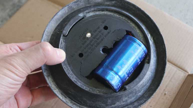
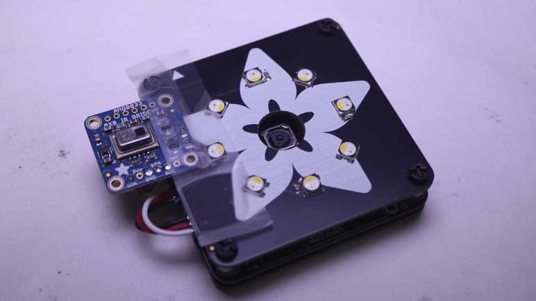
These lenses fits disturbingly loosely in their mount, far short of the level of precision I associate with Canon cameras’ EF lens mount. But it gives me confidence I can match that (lack of) precision with 3D printing. Each lens is fastened with a pair of M3 heat-set inserts and I have lots of that, too. This lens mount mechanism leaves the door wide open for optical experimentation. Which is great for the future, but today I want to better understand this trio. My Adafruit Memento thermal camera was still on my workbench, so I used its front face plate RGB LED as the test subject.

Lens “A” Near and Far

When I pulled this microscope out of the box, lens “A” was the one already installed. I understand it is equivalent to the fixed-lens counterpart of this microscope, and it proved to be the most versatile of the trio.

Here is the view with Lens A roughly 320mm away from the LED. This is probably sufficient for surface mount soldering work. I have a Digi-Key ruler here for scale. Note the IC in the middle of the LED, roughly 0.5mm in length, because that’s what I’m zooming in on.

And here it is with Lens A roughly 12mm away from the LED. The level of magnification is very impressive! But unfortunately it is way past my ability of getting a sharp picture. Part of this is the extremely shallow depth of field. Focus is done manually with a knob on the camera, so turning it exerts some pressure. I can turn the knob to the best focus of my ability but, when I release my hand, that tiny bit of flex moves the camera off focus.

The sharpness of this picture was also limited by the LED module’s clear plastic cover, which was not intended to give me a clear view of the chip.

Oh, and that little black speck near the 4 o’clock position? That’s inside the camera. I could disassemble the camera to try to clean it off, but doing so may introduce even more specks. So I will leave the spot, which will now be the signature of this microscope on every picture I take with it.

Lens “L” Near and Far

I raised the microscope back up and changed lens to “L”.

Here’s the view through “L” roughly 300mm from the LED. It has a tighter field of view than “A” at a similar distance.

And here it is roughly 90mm from the LED, as close it can get while still in focus. Again this is a tighter view than “A” at a similar distance, but in both cases I can move “A” closer to obtain the same picture. So what’s the point? I think of “L” as a telephoto lens, used to take close-up pictures without getting close. Like National Geographic photographers who don’t want to get eaten by the lions they’re photographing, or someone who don’t want to scare a mama bird away from her nest. In this application, it means “L” would be useful for soldering work where I want the camera out of the way of my soldering iron, far from sputtering flux, etc. but still offer a closer view than what I can get from lens “A” at the same distance.

Lens “D” Near And… Well, Just Near

And finally I switched to lens “D”. With a listed distance from object of 4-5mm, there’s not much range of motion. Such close distance also means it’s really hard to aim LED illumination into that narrow gap from the side, as the lens cast a shadow otherwise. This lens is best suited for illumination from the back, like science lab microscopes projecting light from beneath a glass slide. (A set of five prepared sample glass slides and an illuminated slide holder was included in the box, which was a novelty but not why I bought this thing.)

Back to the Memento LED, I could get even closer to the little chip inside. Again I had to deal with a very shallow depth of field. In this picture I focused on the chip itself, and we can barely make out some features etched on the chip. Quite impressive especially since we’re peering through the LED module’s not-perfectly-smooth plastic cover.

The narrow range of lens “D” has an upside: it means the entire range of my focus adjustment knob is divided across a much shallower range of focus. In other words, it is easier to find the best focus I can and, when I let go with my hand, the spring-back doesn’t move as far off-focus as when using lens “A”.

Recommendation Depends On Usage Scenario

Given this first round of experiments, I think most people would be well served by a fixed-lens counterpart permanently mounted with the equivalent of lens “A”. With identical electronics (sensor, screen, HDMI-out, etc.) it offers all important capabilities for a lower price. That said, I am happy with my purchase. Even though I felt this trio of lenses fail to justify the price premium, I didn’t just buy the lenses. I also bought the lens mount and I think the real value lay in future optical experiments with that mount. And if I never get around to those experiments because I got distracted, well, that’s not the microscope’s fault.


(*) Disclosure: As an Amazon Associate I earn from qualifying purchases.

Revisiting Budget Digital Microscopes

After wrapping up a thermal camera project, my mind turned to other things I can’t see with my unassisted eyes. So I revisited the market of affordable digital microscopes and decided to try an Andonstar AD246S-M (*). Verdict: I’m happy with my purchase, but knowing what I know now, a cheaper option would have been fine.

Previously…

Years ago I bought a cheap microscope (~$30 *) which acted like a webcam when plugged into my computer. Except instead of showing my face for a video conference, it showed whatever I could bring into focus for magnification. Appropriate for the price point, it was a neat toy but not a great microscope. I think the native sensor resolution was at most 640×480, the optics were not sharp, and the ring of illumination LEDs surrounding its lens caused a lot of glare. And that’s when it worked properly! After some use, my unit started locking up whenever I brought the picture into focus. I hypothesize there was a problem with data processing or transmission. A blurry picture compresses well and doesn’t require much bandwidth to transmit. A focused picture demands more and apparently too much for the the thing to handle. A microscope that runs only when out-of-focus is useless, so it ended up as teardown fodder for 2019/10/15 session of Disassembly Academy.

Market Survey

But I liked the idea enough for another try. Looking at Amazon listings for “digital microscope”, I see the cheap toy is now only about $20. I’m willing to spend more for a better product, what will I get for my money?

  • Listings over $30 usually have a sturdier stand. This is not a big deal, I can build one if it’s important to me.
  • Listings over $60 have integrated screens. I like the idea of standalone operation. If the USB connection craps out, it’s still a functional tool. Add-on features like adjustable stands and LED illumination start coming into play, but as they’re not core to the electronics they’re things I can do myself.
  • Listings over $90 start talking about 1080P resolution, implying the cheaper options are lower resolution. They also start integrating features like an HDMI-out port and saving pictures to a memory card, stuff I can’t add on my own later. (In hindsight, this is the sweet spot.)
  • Listings over $120 start offering interchangeable lenses. Interchangeable lenses would give me more options now, and leave the door open for future projects in optical experimentation. (Andonstar’s AD246S-M slotted here in my hierarchy.)
  • Listings over $150 seems to be past the point of diminishing returns. For example, some have screens 10″ diagonal or larger, which isn’t as important when I can connect even larger screens via HDMI. We also get into quality improvements that are difficult to filter on Amazon. Quantifying lens quality is complicated. Same for camera sensitivity and dynamic range, etc.

I decided I didn’t know enough to judge improvements offered by products over ~$150. The listings continue all the way up to microscopes costing many thousands of dollars. Personally I wouldn’t buy any of those from random Amazon vendors, at those price points I’d rather buy from a known vendor of industrial/scientific equipment.

I’m here in the cheap end, where lenses are probably plastic and resolution claims are highly suspect. I am willing to believe claims of up to 1080P, as there exist lots of inexpensive webcam sensors and screens at 1080P, but anything higher is likely interpolated. Andonstar AD246S-M claimed UHD, a claim I doubt, but the rest of it looks interesting enough for me to try.


(*) Disclosure: As an Amazon Associate I earn from qualifying purchases.

Adafruit Memento + AMG8833: Upgrade Scotch Tape to Servo Tape

I taped an AMG8833 thermal sensor to my Adafruit Memento camera to create a thermal vision camera, and finally got my code fast enough to keep up with the sensor’s speed limit at around ten frames per second. It turned out to be a great practice lesson in CircuitPython performance optimization! Now I need to wrap up some loose ends.

There was one little change on the software side: because I’m using color to represent temperature, sometimes color in the real world can be confusing. So I flipped the visual camera mode to black-and-white ensuring all color visible on screen comes from thermal data.

Then I worked on improving how the AMG8833 is mounted. I used cellophane tape because it was quick and easy and good enough for me to start experimenting. But it’s pretty fragile and would not fit in the Memento carrying case that came as part of Adabox 021. Now that the experiment is a success, it’s worth effort to make a better mount.

The sensor is now protected by a bit of transparent heat-shrink tubing, and the wires were re-soldered so they exit out the side instead of back.

I then used some double-sided foam tape to attach the sensor module closer to the visual camera module. This position blocked three of the front panel LEDs but I haven’t been using them anyway.

And now it fits in carrying case! I thought having a thermal camera would be neat, but I was never sure how much I would actually use one. Now I have a low resolution DIY version, I’ll see if it comes in handy. I can see several future possibilities:

  1. I might take this apart for another project idea. For one thing, this project didn’t make use of Memento’s photography capabilities at all and I think that’s a shame.
  2. Maybe I’ll upgrade to a better sensor module breakout board.
  3. Maybe I’ll decide a thermal camera is useful enough to finally buy a FLIR ONE for myself.

Time will tell.

For now, I’m still thinking about electronics that help me see what I can’t see with my own eyes. Thermal cameras do that, and so do microscopes.

Adafruit Memento + AMG8833: NumPy and List Comprehension

Pairing an AMG8833 thermal sensor with an Adafruit Memento camera gave me a thermal camera, but my code was running quite slowly. I found an example illustrating use of (ulab.numpy subset of) NumPy for interpolating data from AGM8833’s sensor grid to a larger grid, and adapted it to my project. My performance marker timers say this resulted in total of ~320ms per frame, or roughly 3 frames per second. Here’s an excerpt from rendering four frames:

read 38028 scaled 596 mapped 1520 blit 27626 grid 224501 refresh 24528 total 316799
read 38237 scaled 596 mapped 1520 blit 28789 grid 223636 refresh 24438 total 317216
read 38296 scaled 566 mapped 1580 blit 27567 grid 226170 refresh 24438 total 318617
read 38356 scaled 626 mapped 1728 blit 28849 grid 198901 refresh 24587 total 293047

More important than the interpolation itself was having an example for me to study NumPy. My takeaway is to avoid writing loops iterating through arrays as much as possible. Almost every performance win here boils down to substituting a tightly iterating loop with a single operation.

Bitmap as NumPy Array

The biggest win was converting my thermal overlay drawing commands into a single NumPy operation. The critical part is creating a ndarray view on top of existing bitmap data in order to avoid copying its bits around.

output_ndview = np.frombuffer(output_bitmap,dtype=np.uint16).reshape((240,240))

This was the key allowing me to describe large scale bitmap operations without having to write my own for loops to iterate over x,y coordinates. The loops are still happening, of course, but now they’re within fast native code free of Python runtime overhead.

Subset Blues

I knew ulab.numpy was a subset of full NumPy and was curious if the missing parts would be something I wished for or if they’re too esoteric and I wouldn’t miss their absence. The answer is the former: even as a beginner I quickly ran into situations where I found a NumPy answer on something like a Stackoverflow thread only to find features missing from ulab.numpy. One example is repeat(), which I replaced with my own series of unrolled copy operations.

List Comprehension For Palette Lookup

The final bit of code to be replaced by NumPy operations was a thermal color palette lookup. My first implementation did it easily with nested for loops iterating through x and y axis, but it’s not fast. This feels like an operation that might have a NumPy operator, but nothing in ulab.numpy sounded applicable. Full NumPy offers a way to execute an arbitrary Python function over every element in an array, but that was missing from ulab.numpy. After reading through several Stackoverflow threads I decided to create a list comprehension out of palette lookup and build a NumPy array around the list. I’ve already explained why I didn’t like list comprehensions, but performance numbers don’t lie: performing palette lookup via list comprehension was at least an order of magnitude faster. For that kind of gain, I’ll hold my nose and use a list comprehension.

Final Results

I’ve replaced almost every for loop in my old code with NumPy operations, the only remaining inner loop for generates my list comprehension. All of these changes add up to quite an improvement. As can be seen in these times involved in generating four frames:

read 38624 scaled 775 interpolated 1132 mapped 2444 blit 28551 grid 6199 refresh 25361 total 103086
read 38624 scaled 626 interpolated 924 mapped 2175 blit 28730 grid 33319 refresh 25153 total 129551
read 38594 scaled 685 interpolated 1043 mapped 2295 blit 27716 grid 6288 refresh 25452 total 102073
read 38504 scaled 656 interpolated 924 mapped 2295 blit 28044 grid 33289 refresh 25213 total 128925

As low as 102ms, almost 10fps, which is great! In fact, it marks the finish line. 9-10fps is as fast as the AMG8833 can deliver due to legal limitations imposed on thermal sensors. Going faster won’t gain anything thus ends this practice session of CircuitPython performance optimization. I will wrap up a few details and move on to the next project.


https://github.com/Roger-random/circuitpython_tests/blob/main/pycamera_amg88xx/code.py

Adafruit Memento + AMG8833: Add Interpolation

I paired an AMG8833 thermal sensor with my Adafruit Memento camera to build a thermal camera. I expected it to be an instructional learning project, I just didn’t expect it to be a learning project about CircuitPython performance. First step was to add performance timers to quantify impact of future enhancements, which gave me a baseline. Here’s an excerpt reflecting four frames rendered using TileGrid:

read 38087 scaled 3099 mapped 1789 grid 1728 blit 28223 refresh 360370 total 433296
read 37789 scaled 3099 mapped 1759 grid 1758 blit 30190 refresh 359803 total 434398
read 38713 scaled 3129 mapped 1788 grid 1729 blit 29683 refresh 362098 total 437140
read 38296 scaled 3129 mapped 1758 grid 1759 blit 29146 refresh 360579 total 434667

Total time per frame of roughly 430ms means a little over 2 frames per second.

Back to Bitmap

I converted the code back to my naive dot-drawing code, which showed better numbers. Again, an excerpt of four frames:

read 37760 scaled 3368 mapped 1609 blit 27239 grid 146836 refresh 24468 total 241280
read 38266 scaled 3099 mapped 1580 blit 27239 grid 118077 refresh 24557 total 212818
read 38206 scaled 3368 mapped 1609 blit 27746 grid 144750 refresh 24527 total 240206
read 38237 scaled 3367 mapped 1610 blit 27269 grid 144750 refresh 24378 total 239611

My dot-drawing code is within the “grid” bracket and that’s why it got a lot slower. And “refresh” is technically wrong as I’m no longer calling display.refresh(). I’m actually calling pycam.blit() but since I’m already using the “blit” label for something else I left the label as “refresh”.

At a total cycle time of under 240ms, this was about 4 fps and almost double the speed of my TileGrid version. This is still very slow but the good news is the slowest parts are now code under my control.

Add Interpolation

With code under my control, NumPy experiment begins. I started by adapted PyGamer Thermal Camera code to my project. It replaced my old code within “scaled” and output a 15×15 array of interpolated values. Despite this added functionality, execution time dropped from ~3.3ms to ~0.6ms. Nice!

Unfortunately overall frame rate dropped from ~4fps to ~3fps because “grid” got slower: it now has to draw a thermal overlay of 15×15 data points instead of just 8×8.

read 38028 scaled 596 mapped 1520 blit 27626 grid 224501 refresh 24528 total 316799
read 38237 scaled 596 mapped 1520 blit 28789 grid 223636 refresh 24438 total 317216
read 38296 scaled 566 mapped 1580 blit 27567 grid 226170 refresh 24438 total 318617
read 38356 scaled 626 mapped 1728 blit 28849 grid 198901 refresh 24587 total 293047

Slower frame rate is only a temporary setback, because this example helped me learn how (the ulab.numpy subset of) NumPy can be applied to my project. These lessons helped me unlock additional performance gains.