Yesterday I got a “Joule Thief” (a.k.a. Armstrong self-oscillating voltage booster) circuit up and running on a breadboard. The circuit was more complex than it needed to be, with a tangle of wires, because things got messy while debugging. But now that I know which parts connect to which, it’s time to simplify.
The goal is to make it small and compact enough to package together as a single-battery LED flashlight. That general goal broke down to the following parts:
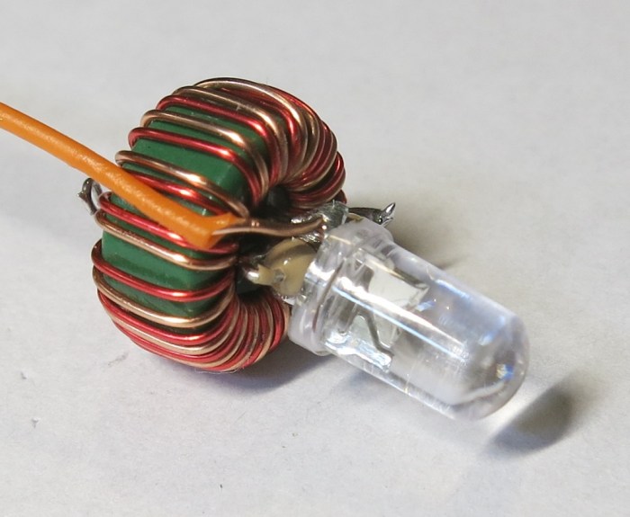
- Minimize physical size. Since the coil is the largest single piece (other than the AA battery) it makes sense to align the diameter of the coil to the battery and pack everything else as tightly inside as I can.
- Minimize component count. Most Joule Thief examples on the internet (including the top picture on the Wikipedia page) soldered the legs of the individual components together. No circuit board needed.
- Friendly to hand soldering. There are some ready-made Joule Thief circuits for sale on the internet using surface mount components and a circuit board. I wanted something I can build by hand and maybe use as a soldering teaching project to be shared on the internet.
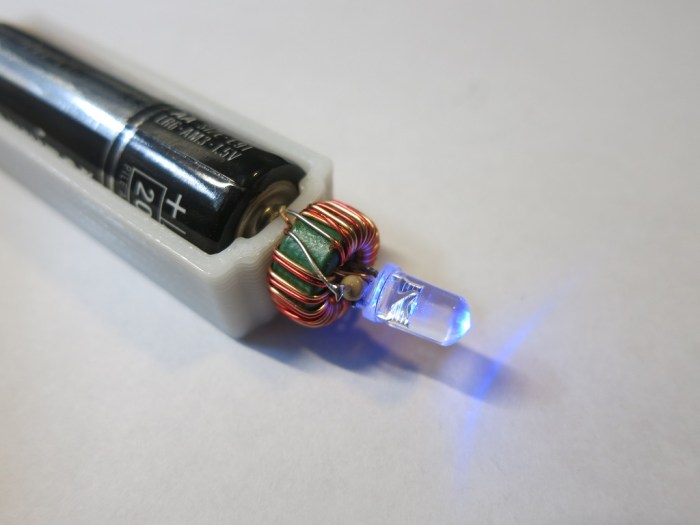
After a few iterations, I have something I’m happy to share with the world. This is purely about the mechanical assembly – the electronic schematic is identical to the one in the Wikipedia article linked at the top of this post.
An overview in words:
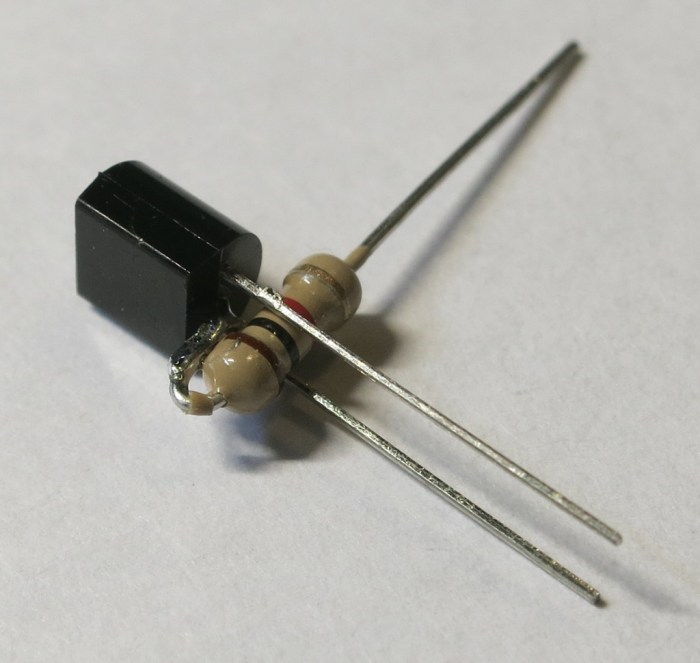
- The resistor for the NPN transistor base is installed between the collector and emitter. The resistor acts as physical separation in order to avoid a short-circuit.
- The transistor and LED are pointing in opposite directions, allowing their pins to point towards each other and soldered together. The aforementioned resistor keeps the LED anode and cathode separate.
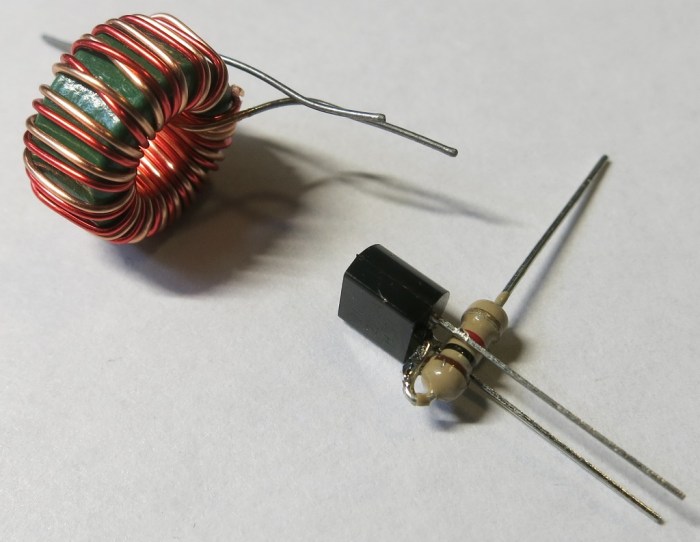
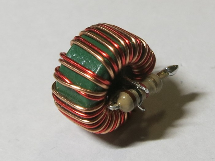
- The transistor is stuffed into the middle of the coil, utilizing the center volume.
The build sequence in pictures: