I quickly discovered several reasons why a computer monitor makes for a poor lamp within an hour of bolting one to the bottom of an IKEA LACK coffee table serving as horizontal mounting stand. The original motivation was to have a for a polarized light source and it worked well enough to give me a few neat pictures. But its inefficiency meant it was relative dim for the power consumed, turning that power into a lot of heat, and it made non-backlit LCD screens (with their own polarization filters) unreadable at certain angles.
I still want polarized light capability for my workbench light, but it should be an optional component for only when it is useful. Similar to the corresponding camera lens polarization filter which I can remove as needed. I also want the light to be more efficient so it doesn’t waste as much power as heat. Leading to my next attempt, pulling from my stack of salvaged laptop screen backlights. They are very energy efficient as they were designed for battery-powered devices. I had successfully transferred a few of their corresponding polarization filters to a sheet of clear acrylic. And I kept the laptop lid backing to serve as mechanical mounting frames. This is what I will convert to an energy efficient polarization-optional workbench light.
There’s a LED controller with associated voltage boost converter on this circuit board, but this time I’m going with the brute-force approach just to see how well it works. If I burn out something, that’s a lesson learned! If it works well enough, that saves me the effort of trying to figure out how to interface with a backlight controller.
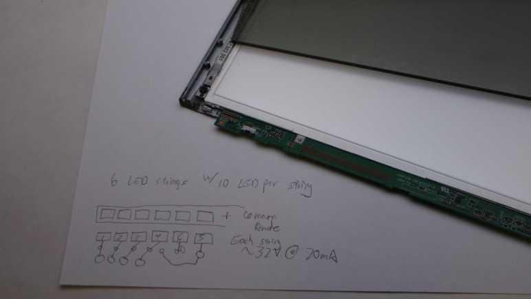
The backlight FPC (flexible printed circuit) connector is too small for me to use comfortably, so I’m going to repurpose just one end of the original circuit board. Using my LED backlight tester, I mapped out the copper pads corresponding to LEDs. In this specific example, there are six parallel strings that draw 20mA at around 32.2V. Since white LEDs in my experience drop a little over 3V each, that implied each string had 10 LEDs. 6*10 = 60 small surface-mounted LEDs inside this backlight module should shine quite nicely, once I find a way to power them.
I mounted a somewhat broken Monoprice 30″ monitor (10734) under an IKEA LACK coffee table so it would face downwards. Combined with an ESP32 perpetually generating an all-white VGA signal, it would shine polarized light on my workbench so I can take cool pictures of my projects. After proving the concept basically worked with those pictures, this first-hand experience also quickly exposed some problems with this idea.
It Makes Other LCD Hard to Read
Using polarized light to illuminate my workbench caused the unexpected (but hilarious in hindsight) problem of making other LCD panels hard to read. LCD with their own light sources (backlights) are OK, like cell phone screens and digital camera displays. But LCD without their own lights, such as that on a multimeter, are only readable at certain angles. This is the same reason why I have to tilt my head at a specific angle when trying to read my car’s LCD information while wearing polarized sunglasses, and it’s just as annoying.
It Is Pretty Dim
Despite the shiny effects we see in movies, computer monitors aren’t designed to be light sources and are pretty bad when drafted into the role. Screen backlights are quite bright when shining alone, but this one is still shining through many layers necessary to make a computer monitor function. Here’s a picture I took earlier of a different panel, showing the brightness difference between a backlight by itself versus when one is still part of a functioning display.
A lot of light energy is lost between those functional layers, and that lost energy is eventually dissipated as heat, leading to the next problem.
It Gets Really Hot
This thing runs hot and being mounted horizontally under a coffee table made the problem worse. The convection cooling vents are now oriented the wrong way. And even worse, an IKEA LACK coffee table is mostly empty space inside, acting as a layer of insulating blanket preventing the monitor from shedding its heat buildup. With the closest edge sitting only about 10cm from my forehead when I’m sitting at my workbench, I can easily feel heat radiating from this thing. Not a pleasant thing in my face in the already warm environment of Southern California. After 15-20 minutes of use, the metal enclosure becomes uncomfortably hot to the touch, leading to the next problem.
It is Glitchy
Once the system is uncomfortably hot, the screen begins blinking at irregular intervals. I interpret it as an indication of an overheating system. When the outside enclosure is too hot to touch, the electronics inside has likely gone beyond its normal operating temperature envelope. A flicking workbench light is worse than useless.
Now What?
I think the heat dissipation problem is fixable, with two ideas immediately and probably more if I think about it longer:
Mount it on something other than an IKEA LACK, something that allows heat to rise away from the hot metal enclosure. This may be an official monitor mounting solution or another hacked-up stand.
Add one or more cooling fans for active cooling.
But improving heat dissipation would not address the original inefficiency that generated all that heat to begin with, it would not make the illumination any brighter, and it would not make my multimeter screen more readable. Given these serious problems, I declared the “monitor as lamp” experiment a failure. I’ll try a different approach to workbench lighting.
When I decided to play with polarized light photography, I knew I would need a source for polarized light in addition to buying a polarizer filter for my camera. And I had just the thing: an old and strangely malfunctioning Monoprice monitor (10734) that has been converted to become a lighting panel for diffuse white light by feeding it a pure white VGA video signal. I didn’t originally have polarization in mind when I started that project, but I knew LCD displays work via light polarization. As soon as I started thinking about a polarized light source, it was an obvious fit. This was once an expensive and capable computer monitor and I hoped I could put it to work again.
Using a monitor as a light panel means installing the monitor facing downwards. This isn’t something the stock monitor stand could handle, neither could most aftermarket monitor mounting solutions. I found a few that can possibly work and handle the weight (it’s a pretty heavy monitor) but they cost more than I wanted to spend for an experiment. So I’m going to mount it to the bottom of an old beat up IKEA Lack coffee table.
Since LACK furniture is mostly hollow, I didn’t expect to be able to handle the weight concentrated on a few bolt heads. Fortunately, the stock monitor stand has a metal plate I could use to spread the weight across a larger area.
The plate was useful as a drilling template as well. I drilled four holes for M4 x 60mm hex bolts then mounted the plate on the table top.
I then threaded those four bolts into the monitor’s mounting holes, making for a secure fit. I lifted this coffee table over my workbench, now it is illuminated by a 30″ polarized light panel! I’m glad I didn’t spend too much money on a fancy stand for this experiment, because a few problems quickly became apparent.
Starting with the recent Philips Sonicare teardown investigation, I’ve reintroduced the use of my Canon EOS M100 camera to take pictures for project documentation. Its excellent sensor paired with a macro lens for close-up photography work quite well to capture small surface-mount components and related circuitry detail. Late in the investigation, I added polarizers to the setup and was amazed at how much of a difference it makes under the right circumstances.
My current understanding is: if I use a light source that is polarized in a direction, then take a photograph with a filter polarized in an orthogonal direction, most direct reflections are eliminated. This means the resulting pictures will not be blown out by reflective glare, even though the subject can be very brightly lit Letting us make out details we could not otherwise see.
Here’s the Sonicare HX6530 circuit board again, taken without polarizers. All the solder pads are very shiny, as are some of the circuit board surfaces. I tell the camera to focus on the markings on the surface of the PIC16F726 microcontroller, but we can barely make it out.
And now a picture taken with polarization. All the shiny reflections are gone, letting us see far more detail that were previously obscured. PIC16F726’s markings are now clearly legible.
This is a great tool to add to the project documentation photography toolbox, but like all tools there are right and wrong times to use them. Even though I can see details with the polarizer in place, some of those details may be misleading. Example: actuator coil pads 1 and 2 show up as red in the polarized picture above. I don’t know why but it tells me to view colors in polarized pictures with skepticism.
But sometimes polarizers are just magic. There’s clear packing tape protecting this solder joint. Normally the tape would directly reflect light into the camera sensor, causing a bright glare on the surface making this solder joint impossible to photograph. But a polarizer can filter out that glare and let the camera focus on the solder joint almost as if the packing tape isn’t there. The downside of removing bright reflection is that it also removes a lot of visual cues for dimensions. Look at the red wire: all visual cues it is cylindrical are gone leaving it looking like a flat red thing.
Polarizer filters are sold for camera lenses for use in this and other scenarios. The Canon EF-M macro lens takes 43mm filters so I started with the cheapest option on Amazon (*) to see how well it worked. The outer ring is assembled from two parts: one part threads onto the lens and stays put, the other part holding the filter rotates freely letting me adjust the polarization angle. These initial tests look promising so I’ll use the cheap filter until I can articulate a reason to move upscale.
The camera lens polarizer is cheap to buy and easy to use, but getting these results also require a source of polarized light. I think the easy solution is to buy sheets of polarizer film (*) and put it over your existing light sources, but that’s not what I did. I wanted to put some old stuff to work.
(*) Disclosure: As an Amazon Associate I earn from qualifying purchases.
Recent changes to Chrome browser motivated me switch to Firefox, but that wasn’t the only recent Google decision that irked me. Google also decided to be a lot less generous with Google Drive. Google Pixel camera images received unlimited Google Drive backup storage, but that perk ended with the Pixel 5. Images from Pixel phones newer than Pixel 5 count against Drive limit just like any other data. I guess Google is no longer funding the Drive division for supporting Google hardware adoption.
It was very convenient to document my projects with my phone camera as it is usually nearby. But being generous with the shutter also meant I was quickly filling up my Google Drive quota. With the flood of nag mail demanding I pay money to increase my quota, I was motivated to migrate from cloud-based storage back to local storage on my TrueNAS array. And if I’m doing that anyway, I might as well dust off my Canon EOS M100 camera. Shown here with a lens for up-close photography and a wrist strap (*) far less bulky than the standard neck strap.
Convenience of cloud backup was a major reason why my M100 had been gathering dust. Now that Google has made it less enticing, I’m returning to the superior photography capability I’ve already paid for. The M200 is the current successor but I don’t feel a need to upgrade yet. Even this older M100 has sensor and lenses that easily outperform a phone camera, even more so when dealing with projects like my Sonicare HX6530 circuit board.
Credit to the Pixel 7 camera design team, it performs well with subjects at normal ranges. But I would not call my usage pattern normal, and I’ve highlighted problems before.
Above is a serviceable picture taken by the Pixel 7, below is from the M100.
When scaled to blog post size, they’re pretty close. But when I want to crop, the M100 sensor delivers more pixels to work with. Here are 1:1 pixel crops from original resolution of above images:
The M100 gives me more pixels to crop closer to the subject. The Pixel 7 is quite competitive here looking at the center of the image, but it falls behind when we start looking towards the edge:
Both lenses degraded as we move away from the center, but the EF-M Macro lens does a better job. And while the phone camera couldn’t focus much closer than these pictures here, the Canon lens can focus far closer. So close, in fact, that the lens itself casts a shadow blocking surrounding light. Which is why it has a built-in ring light to handle those cases.
So a dedicated camera has a better sensor. In front of that better sensor is a better lens, which can be swapped out for different lenses optimized for specific scenarios. And in front of that lens is a finely threaded mount for lens filters, which adds even more capability. For my electronics project photography, adding a polarized filter is a magical transformation.
(*) Disclosure: As an Amazon Associate I earn from qualifying purchases.
One of the reasons I started looking at Angular web development framework a few years ago was because it was backed by Google and I saw that as a positive thing at the time. One of the reasons I looked at Marko web development framework now is because I no longer see Google backing as a positive thing.
I remember Google when it was a young and idealistic startup and today’s mega corporation has strayed quite far from its “Don’t be evil” origins. A few years ago I would enthusiastically add new Google products to my life. Today I am skeptical of new Google launches, due to fiascos like Stadia and disruptions caused by their historical tendencies to kill products. And of the Google products I’m already using, I keep my eyes open for alternatives that might help me reduce Google’s grip on my digital life.
As part of this transition, I’m working to reduce reliance on Google’s Chrome browser. I have Firefox installed but remembering to use it instead of Chrome requires breaking longtime habits. My latest motivation to do so is Google’s aggressive push for additional user tracking to increase its advertising revenue, and maybe this time my switchover will stick. I plan to keep Chrome around to run Google-specific properties like Gmail and YouTube (since Google is tracking me there anyway) but use Firefox for everything else.
So far there’s nothing in Firefox that made me regret switching, and I’ve found a feature that might make the switch worthwhile all on its own: I can make Firefox PDF viewer default to “Page Fit”!
I remember when downloading Adobe’s free Acrobat reader was a standard part of setting up a new machine. Today, PDF’s ubiquity meant browsers tend to include PDF viewing capability. I’m tired of Adobe trying sneaky things to generate revenue from free Acrobat reader, so I am happy to skip that download. But there was one little annoyance: I prefer to read my PDF with each page zoomed to fit the window. I know how to set that default on Acrobat reader but that’s not how it opens by default in a browser’s integrated PDF viewer window.
I never found a way to do what I want in Chrome’s PDF viewer. Microsoft’s Chromium-based Edge browser is a little better: there’s a keyboard shortcut Control + “\” to change zoom setting. I got in the habit of pressing Control+”\” twice whenever I opened a PDF in Edge, which zooms to page, but it would be nice if I didn’t even have to do that. A web search found confirmation this was not possible in Edge.
By default, Firefox opens PDF in “Automatic Zoom” mode, which isn’t what I want. I searched for a Firefox equivalent to Control+”\” in Edge but I found something better: this support page with instructions on how to change that default, it even had a link to the GitHub pull request that implemented the feature. Sweet!
In case those links go dead in the future, here’s the summary:
Type “about:config” into Firefox address bar
We will see a warning screen and we have to decide to accept the risk and continue.
In the search box, type “pdfjs.defaultZoomValue“
Click the pencil to edit.
Type in page-fit. (Or, if that’s not personal preference, one of the following supported options: auto, page-actual, page-fit or page-width.)
Click the check icon to save.
Now Firefox PDF viewer will open with my preferred zoom setting, no need to press Control+”\” twice.
If Google had left Chrome alone as a consumer-friendly browser, I don’t know if Firefox PDF default zoom capability would have enticed me to switch. However, now that Google is getting greedy and I’m starting to use Firefox, this feature is definitely one that will make me want to stay with Firefox. In the meantime, another Google “revenue enhancement” policy change motivated me to start using a real camera again.
While I’m window-shopping open-source software like Godot Game Engine, I might as well jot down a few notes in another open-source package. Marko is a web app framework for building user interfaces. Many web development frameworks are free open source so, unlike Godot, that wasn’t why Marko got on my radar.
The starting point was this Mastodon post boosted by someone on my follow list, linking to an article “Why not React?” explaining how React (another client-side web development framework) was built to solve certain problems but solved them in a way that made it very hard to build a high performance React application.
The author asserted that React was built so teams at Facebook can work together to ship features, isolating each team from the implementation details of components created by other teams. This was an important feature for Facebook, because it also meant teams are isolated from each other’s organizational drama. However, such isolation meant many levels of runtime indirection that takes time every time some little event happens.
There was also a brief mention of Angular, the web framework I’ve occasionally put time into learning. And here the author asserted that Angular was built so Google can build large-scale desktop applications that run in a web browser. Born into a world where code lives and runs in an always-open browser tab on a desktop computer, Angular grew up in an environment of high bandwidth and plentiful processing power. Then Google realized more of the world’s internet access are done from phones than from desktop computers, and Angular doesn’t work as well in such environments of limited bandwidth and processing power.
What’s the solution? The author is a proponent of streamed HTML, a feature so obscure that it doesn’t even get called a consistent name. The underlying browser support has existed for most of the history of browsers, yet it hasn’t been commonly used. Perhaps (this is my guess) the fact it is so old made it hard to stand out in the “oh new shiny!” nature of web evolution and the ADHD behavior it forces on web developers. It also breaks the common path pattern for many popular web frameworks, roughly analogous to Unity DOTS or entity component systems.
What’s the solution? Use a framework that supports streamed HTML at its core. Marko was originally developed by eBay to help make browsing auctions fast and responsive. While it has evolved from there (here’s a history of Marko up to the publishing date in 2017) it has maintained that focus on keeping things responsive for users. One of the more recent evolutions is allowing Progressive Web Apps (PWA) to be built with Marko.
It all sounds very good, but Marko is incompatible with one of my usage scenarios. Marko’s magic comes from server-side and client-side runtime components working together. They minimize the computational requirements on the client browser (friendlier to phones) and also to minimize the amount of data transmitted (friendlier to data plans.) However, this also means Marko is not compatible with static web servers where there is no server-side computation at all. (Well, not impossible. But if Marko is built for static serving, it loses much of its advantages.) This means when I build a web app to be served from an ESP32, Marko might not be the best option. Marko grew up in an environment where the server-side resources (of eBay) is vastly greater than whatever is on the client. When I’m serving from an ESP32, the situation is reversed: the phone browser has more memory, storage, and computing power.
I’m going to keep Marko on my mind if I ever build a web app that can take benefit from Marko’s advantages, but from this cursory glance I already know it won’t be the right hammer for every nail. As opposed to today’s web browsers, which try to do it all and hence have grown to become Swiss Army Knife of software packed with capabilities like PDF document viewers.
The most important value proposition of a game engine is cross-platform capability. Godot has that pretty well covered. Godot editor can run on all the desktop platforms I care about: Windows, Linux, and MacOS. There’s even a native Apple Silicon build, something Unity only started offering a few months ago.
Godot engine can export to all the target platforms I care about: All the editor platforms I listed above plus iOS, Android, and web. Android and web are actually supported editor platforms as well, but I do not expect to use them. I do not expect support for IE11 (Windows Phone browser) but neither does Unity so that is at parity.
Unlike the commercial offerings, Godot has no official solution for console games because console SDKs are all under NDA protection at odds with an open-source model. It’s possible, but not supported, but I don’t care about that myself anyway.
VR Support
Godot supports OpenXR, which is the open-source entry point to hardware like Valve SteamVR and Oculus headsets. Godot also has support for Apple’s ARKit but I didn’t see any mention of Google’s ARCore. Fundamentally, XR support in Godot is a function of whatever support they receive for it. Whether in the form of volunteer contributors, donated test hardware, or just straight up cash.
Entity Component System/Data Oriented Design
Based on customer feedback, Unity offers their DOTS “Data Oriented Technology Stack” built on an entity component system. This opens things up for those who want to adopt data-oriented design for their software architecture. (A counterpart of object-oriented programming.)
Godot explains why they’re not terribly eager to follow in these footsteps, because data-oriented design requires a different mindset not terribly intuitive for the human mind. Partially because we have to consider nuts and bolts of CPU cache behavior. We usually have the luxury of ignoring those details as an abstraction! All that said, Godot is not forbidding data-oriented development, the document even shares a few links to resources to help. But it’s not on the main path and unlikely to be.
Reinforcement Learning
I briefly played with the reinforcement learning subset of modern deep machine learning, using Unity as the learning environment. (“Gym”.) I thought the general idea was great, but the field is still quite young. Right now, an absurd amount of computational power is required to learn what a human brain would perceive as simple behavior. I’ve also learned that Unity ML-Agents was not terribly performant, bottlenecked by communication between Unity engine and machine learning frameworks.
A cursory search found several GitHub repositories of people working to bolt Godot and RL frameworks together, whether they share the same performance issues I do not know.
Educational Resources
Learning guides are where Unity has a huge head start, with their longtime investment into Unity Learn building up a huge library of examples and tutorials for all sorts of different domains for a wide range of audiences.
Godot would not be able to match or exceed that in the short term. But supposedly the current popularity of Unity exodus has led to a spike in number of Godot tutorials being published. A rise in quantity is no guarantee of quality, but I’m optimistic that there will be sufficient resources for Godot beginners to start with whenever I choose to join those ranks.
With this quick survey, I saw no deal-breakers against using Godot. The next time I have a project idea that would benefit from being built on top of a game engine, I’ll likely use that as the focus for learning Godot. In the meantime Godot will sit on the “something to learn once I have an appropriate project” list alongside Marko.
I’ve just learned some very valuable electronics lessons, and it was helped by KiCad the free open-source electronics design software. It’s a very large suite of tools but having a specific need in front of me (capture reverse engineered schematics of a circuit board) helped me stay focus and get to the “know enough to do what I need to do” point quickly. I’ve also been learning FreeCAD, another piece of free open-source software, but I haven’t reached that point yet. And now I’m adding another piece of open-source software on the “learn enough to do what I need” list: Godot Engine.
Godot is an alternative to Unity 3D, both offering a game development environment and runtime engine. Unity has lots of learning resources online. It adopts new development paradigms like data-oriented programming, new tools like machine learning, and supports new platforms like virtual reality. It also used to have very beginner-friendly terms and conditions, letting aspiring indie game developer hobbyists play around for free and letting small startups launch. Originally the pitch was: “share your success”. Only after a game studio is successful would Unity start requiring payment. Unfortunately, Unity as a business is changing for the worse.
Recently there’s been an uproar in the game development industry as Unity announced new pricing policies to go into effect at the start of 2024. While price increases happen across the economy on everything we buy, this particular case was deeply antagonizing.
Instead of paying royalties on successful games, it could levy a fee upon every game installation regardless of whether it is a revenue-generating context. This means, for example, successful royalty-paying game studios will be charged for every installation of a free demo whether it turns into a sale or not.
Even though it doesn’t take effect until next year, the new policies could apply retroactively. Games currently in development will be held to different terms than what the project started with. Even worse, it applies to games that have already been released!
Before the announcement, these changes were previewed with a few game studios to get their feedback. After receiving some very negative feedback, Unity went ahead anyway.
The worst part: Unity pulled this stunt once before in 2019 and got flamed for it. They walked back those changes and promised “we heard you” and won’t do it again. Now in 2023, they did it again.
Why is this happening? Money, of course! Unity went public in 2020, which meant a management structure incentivized to “maximize shareholder value”. And the most obvious way to do that was to squeeze game developers for as much as they will tolerate. The proposed 2019 changes were originally intended to improve Unity’s financial outlook pre-IPO but backfired. And now it is obvious Unity’s management has failed to learn the lesson.
As of this writing, Unity is on a damage-control footing walking back their announcement. Again. Will it work a second time? I don’t know. It hasn’t escaped people’s notice that the same management mindset that drove headfirst into this train wreck is still in charge. [Update: CEO has resigned, but the board of directors and senior management are still there.] Notably absent from the current retraction is any legally binding obligation preventing them from trying yet again after this current storm blows over.
So “Fool me once”, and all that. Unity’s largest competitor is Unreal Engine whose licensing terms aren’t as generous, but they also lack a history of such underhanded tactics at changing said terms. Unreal will likely pick up Unity customers who need a mature toolset with leading-edge performance and quality. For those without such requirements, like small indie game studios and aspiring game developer hobbyists, maybe none of these Unity changes affect us today. But we should all be deeply concerned that Unity’s free tier may gradually become crippled in the future if not disappear entirely. Thus, alternatives like Godot Engine deserves a look.
I previously observed the actuator coil ends are alternately energized to battery voltage with the other end at ground for about 1.25ms. Then both ends sat at ground level for around 0.75ms before repeating with the coil energized in the opposite direction.
This time I connected the four channels of my oscilloscope to four test pads each associated with a MOSFET control gate. I started a brush cycle and got this:
There were two mysteries with this plot:
Why are there only two colors visible when four channels are active?
Why is the alternating pattern occurring for 0.75ms (duration of the rest period) at a time, instead of the 1.25ms (duration of the actively energized time)?
I figured out the first one by pushing each of the four channel select buttons in turn, which brings their color to the foreground. It turns out that two of the MOSFETs corresponding to the same end of the coil always receive the same control voltages, so they overlap on the plot and only one of those two colors is visible. The yellow line corresponds to TP3, P-channel MOSFET for coil output 2. It is always in sync and thus plots over the cyan line, which is TP9 and N-channel MOSFET for coil output 2. If I push the channel 3 button (cyan) it would completely obscure the yellow line. Likewise, the green line here is TP10 (N1) masking the magenta line for TP4 (P1). If I press channel 2 (magenta) select, it draws exactly where the green is and mask all green.
It makes some sense for both MOSFETs corresponding to one end of the coil to stay in sync. We want only one of those to be conducting from source to drain at any given time. If they are both active, that would cause a short circuit between the battery power and ground rails. Since one is a P-channel MOSFET and the other a N-channel, both receiving the same signal means one turns on and the other turns off.
But if they are in sync, why bother using two separate control pins from the microcontroller? Why not just have a single signal that goes to both MOSFETs? I learned this was a difference between the ideal world and the real world. In the real world, MOSFETs take a tiny bit of time to ramp up and down. If we use a common signal wire, one MOSFET will start to turn on while the other one is still ramping off within this narrow time window and cause a short circuit. Having two separate control signals allow the microcontroller to turn one off, wait a bit for it to ramp down, before turning the other one on.
If that’s the case, though, it’s not visible in my oscilloscope plot at 1ms/grid resolution. I selected channel 2 (magenta TP4 P1) and 4 (green TP10 N1) and started increasing the time resolution until I saw a clear difference in timing, around 3us apart, between those two signals. I love it when I can see real-world necessities confirmed in an actual implementation like this.
The next challenge is figuring out why MOSFETs look like they’re energizing the coil for 0.75ms out of the cycle, instead of 1.25ms like I expected. It didn’t make sense, so I started questioning my “known facts” until I got to cycle time. I have an oscilloscope plot on hand showing 1.25ms ON time and 0.75ms OFF time, but that wasn’t captured at the same time as the MOSFET signal plots. To verify this “known fact” I moved one of the oscilloscope probes over to coil terminal 1.
The coil is ON for 0.75ms! The “known fact” of 1.25ms ON time was wrong. I had assumed the cycle time would have stayed consistent, but something changed between the previous oscilloscope session and this session to change those cycle times. If it didn’t happen to land inversed from before (say 1.5ms and 0.5ms) I would have realized my assumption was wrong, but it just happened to end up inversed and confused me until I identified my incorrect assumption.
Valuable lesson learned: given the luxury of a multichannel oscilloscope, use those channels to capture related data at the same time. Comparing plots across different instrumentation sessions risks outdated information leading to bad conclusions.
With that, I believe my investigation of Philips Sonicare HX6530 circuit board is complete. I want to apply these lessons and build my own brush actuator control circuit, but that will be a future project. Some unrelated things worth noting happened while I had my nose in this circuit board, starting with how Unity corporation’s management alienated users.
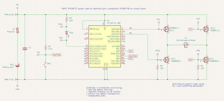
I probed the circuit board salvaged from a retired Philips Sonicare HX6530 electric toothbrush, trying to understand how it controls the brushing actuator. I compiled my findings into a partially reconstructed schematic of this circuit board, and it looks like a H-bridge or at least a similar arrangement of components.
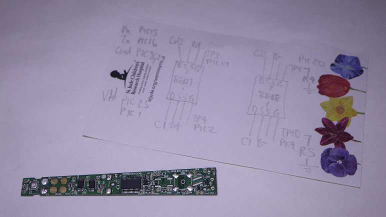
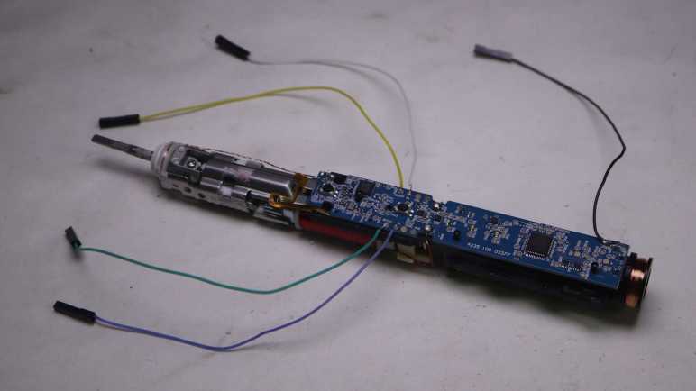
I made effort to figure out which test points corresponded to which locations on this schematic, because that’s my next step: solder wires so I could connect them to my oscilloscope and watch them run. These test points were intended to mesh with a specially designed test harness with pogo pins corresponding to those locations, but I decided that was too much effort for the sake of curiosity and went with direct soldering.
Color coding will help me keep from getting my wires mixed up. Yellow, blue, and green wires were soldered to test points so I could connect them to oscilloscope channels that use similar colors. This idea occurred to me just after I soldered a white wire to TP4. I briefly contemplated unsoldering the white wire and replacing it with a red one for the sake of consistency, but decided three out of four was good enough to avoid ambiguity.
I powered up the control board with my bench power supply set to 4V, here’s what things looked like in an idle state. TP3 and TP4 corresponding to the two P-channel MOSFET gates float at Vcc. TP9 and TP10 correspond to the two N-channel MOSFET gates with pull-down resistors are at ground. This was as expected.
Here’s an oscilloscope plot I captured earlier, measuring two ends of the coil relative to the ground plane of the control board. We see the coil is driven in one direction for roughly 1.25ms, then not powered for about 0.75ms. Then it is driven in the other direction for roughly 1.25ms, followed by another 0.75ms of rest time. Given this plot, I would expect to see MOSFET gate voltages go to a pattern consistent with driving the coil one way for 1.25ms, followed by 0.75ms of idle state, then flip the other way for 1.25ms, and then another 0.75ms of idle, and repeat.
My expectation did not match what I saw on the oscilloscope screen. All four MOSFET gates were raised high for ~1.25ms, followed by 0.75ms of activity in an alternating pattern. I expected an alternating pattern, but that was supposed to run for 1.25ms, not 0.75ms. Furthermore, there were fewer colors visible on screen than I had expected. What happened to cyan and magenta (channel 2 and 3)? I have to dig deeper to understand what I’m seeing.
Armed with the knowledge granted by “Getting Started in KiCad” guide, I can now take bits and pieces of information gleaned from a circuit board and compile them into a partial reverse-engineered schematic. The first (of hopefully many) subject of these exercises is the Philips Sonicare HX6530 circuit board. I looked it over earlier taking note of components I recognized but didn’t dig deeper into how they are connected. For this second pass, I am armed with an electrical continuity meter to probe how they connect.
To trace routes across this circuit board, I started with magnifying glasses but then moved to a digital camera with a macro lens. This allowed me to put pictures of the front and back together in a slide show and rapidly go back and forth between them to trace routes across layer vias. It worked really well this time, and I expect to continue evolving that system in future explorations.
The goal of these exercises is to control the salvaged brush actuator myself, so I focused on the actuator control MOSFETs to the left of the PIC16F726 microcontroller. I worked out most of the circuitry to the left of the PIC16F726 all the way up to the LED at the far left edge. I mostly ignored the other half of the circuit board, as it dealt with charging and unpopulated pads imply absent features. The only thing I worked out on that side is C1 as a decoupling capacitor between Vdd and Gnd.
The user interface button and feedback LED turned out to be straightforward implementations, easily probed so I put them in my schematic. The focus is on the array of four MOSFETs on the right, surrounding the actuator coil.
At a high level, I recognize the arrangement as an H-bridge circuit popular in motor control. I guess this actuator coil is a motor in a sense. But if so, why did Philips engineers decide to implement their own with two components (each a package of dual MOSFETs) instead of using a single-chip H-bridge solution like a DRV8833? It might be cost, or it might be an important difference between this brush actuator and a generic DC motor.
I notice an asymmetry in this circuit. Dual N-channel MOSFETs each got a 33k pull-down resistor (R4 and R5) on their control gates, but the dual P-channel MOSFETs went without any kind of pull-up or pull-down resistor. Why is it OK to leave them floating? I don’t know.
I didn’t find any flyback diodes on this circuit. My rudimentary understanding of driving inductive loads (such as an actuator coil) is that we need flyback diodes to protect the circuit against voltage spikes when the electromagnetic field in the coil collapses. A generic L298N motor driver module has clearly visible diodes for this purpose. Newer motor control modules like DRV8833 has such capability built-in. DRV8833 datasheet section 7.3.2 Bridge Control and Decay Modes cover this topic.. MOSFETs have a “body diode” intrinsic to their design, perhaps they were sufficient for flyback protection?
It was very instructive to poke around this circuit board and assemble the bits and pieces I teased out into a KiCad schematic. It is incomplete and likely inaccurate, and it raised more questions than it answered. All signs that I still have a lot to learn. And I will start by putting the circuit board under my oscilloscope to compare its measured behavior against what I expect from the schematic.
After making my tiny contribution to the “Getting Started in KiCad” guide, I sat down to actually read through it all. I’ve downloaded and installed KiCad 7.0.7 on my computer and followed along with the tutorial. I found it well-written and very informative for getting me started. Which gave me confidence I can make use of KiCad in the future.
However, the guide assumes the reader is familiar with the basics of electronic circuit design, and just needed to know where to find KiCad has organized various basic functionalities. My hypothesis is that six years ago I didn’t have the prerequisite background knowledge and was thus unable to absorb the lesson to make use of KiCad. If that’s the reason I stopped, I choose to celebrate my growth and hope things turn out better this time.
I don’t know why I had the impression KiCad has tightly coupled symbols and component footprints, because the tutorial made it pretty clear that is not the case. Schematic editor and circuit board layout editor are two completely separate modules, and it’s absolutely possible to draw a schematic with generic symbols (drawing from the stock “Devices” library) and never proceed to layout at all. This bodes well for my intended use of KiCad as a reverse-engineering/learning note-taking tool.
Reverse-engineering means I won’t have control over what components are involved in a design. I certainly won’t have all the technical data for all the components. Which is why I appreciated the tutorial covered how to make custom symbols and footprints, it’s not like I can contact a supplier representative to request technical data. There is an official style guide (“KiCad Library Conventions“) for library symbols and footprints. I skimmed through it, but I don’t understand all of it yet. If I do continue using KiCad, I should revisit this link on a regular basis to better align my own creations with official best practices.
One feature I did not expect to find in KiCad was 3D rendering. Not just the circuit board layout, but a rendering complete with components populated on the board. To do this, a design must have 3D model data associated with the footprint and symbol for a part. The tutorial linked to the FreeCAD StepUp Workbench which bridges FreeCAD and KiCad. It allows using FreeCAD to generate 3D model data for KiCad part libraries, and it also exports KiCad generated 3D data into FreeCAD. The latter allows integrating a circuit board with its associated mechanical components. This sounds like a very powerful capability and, if I ever need such capability, I hope I remember to come back and take a closer look.
My current project goal is building a control module for a reciprocating motion actuator salvaged from a Sonicare electric toothbrush. As a side quest to that goal, I’ve decided to pick up learning KiCad again. I played with KiCad 4 around six years ago, but without practice I have forgotten almost everything so I thought I would start at the beginning with KiCad’s “Getting Started in KiCad” guide.
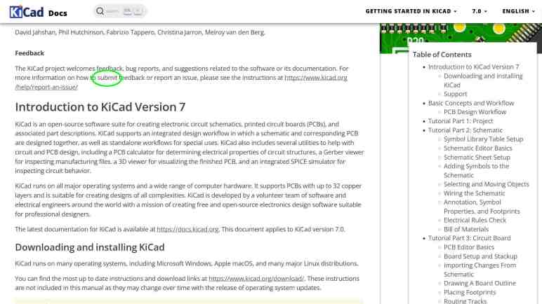
Towards the top of that guide is a “Feedback” section where everyone is invited to help make the project better. Fairly common for free open source projects, but here something caught my eye: a tiny typo of “sumbit” instead of “submit”. Well, they did say they welcome feedback, let me see if I can bring this typo to someone’s attention. I followed the link to instructions on how to “Report an Issue“
Most of the instructions regarding filing an issue concern the software, focused as it was on version/build number and software libraries in play. That wouldn’t strictly apply to reporting a typo, but towards the bottom is a link “I have a docs.kicad.org issue” and I followed that to the kicad-doc-website repository on GitLab. Poking around the directory tree, I couldn’t find any of the documentation information. That was because it was the documentation web site infrastructure (Jekyll scripts, etc) and not the documentation itself. What I’m looking for is the “I have a documentation issue” link to a sibling repository kicad-doc.
Poking around the kicad-doc directory tree was more fruitful. I found getting_started_in_kicad.adoc containing the text for that page. My first objective was to see if the problem has already been fixed. I see the typo in the main branch, so the problem is still there. And since I had the source in hand, I copy/pasted it into Microsoft Word to see if the spell checker can find anything else. It highlighted a few debatable differences in convention (Word wanted “mouse wheel” versus the existing “mousewheel”) and some domain-specific terminology (“opamp”.) I decided they were out of scope for my first run. It did find one other clear problem: a typo “subsitution” which is “substitution” but missing the first “t”.
With these two problems in hand, I will now file an issue. First I had to create a GitLab account, which had been on my to-do list anyway. As part of the sign-up process, GitLab forced me to create a repository pre-populated with a guide to GitLab-specific features as well as general git functionality. This is great to onboard someone new to git-powered source control, but it got in my way today. It took a few minutes before I broke out of the enforced tutorial so I can get back to kicad-doc and file issue #864: Misspellings in “Getting Started” Guide.
Once that was done, I figured I might as well try fixing the problem myself. Trying to edit the original source file resulted in a permission denied error, as expected. But it did launch an automated process to handle small single-file edits. It forked the repository into one I could edit, and then immediately package my edits into a merge request. (“Merge request” is GitLab’s slightly different name for GitHub’s “Pull Request” feature.) I thought this automation handling what would otherwise have been a manual multi-step process was pretty cool! After making my two edits, I put #864 in my description so merge request #909 was automatically attached to my issue #864.
At the same time I was building my GitLab merge request, one of the KiCad documentation maintainers (Graham Keeth) saw my issue #864 and fixed it immediately in the main branch, making my MR#909 superfluous. Graham was apologetic about my wasted effort but I was not offended. I wanted to learn the ropes of contributing to KiCad with reporting an issue, the merge request was a stretch goal. I received advice that I could have mentioned I’ll be working on a merge request when opening the issue. I’ll keep that in mind if I find something else in the future. I got feedback my issue was good, so there’s that.
A tool I’ll need for this job is a circuit diagram a.k.a. electronic schematic. Making notes in the form of word description will only go so far. I can always draw a schematic by hand, and I’ll definitely be drawing fragments as I probe the circuit. But to get a good picture after that, I should transfer that knowledge into a piece of software designed for schematics. (Versus general purpose graphical software like Inkscape.)
Around 2019 I dabbled in Digi-Key’s online tool Scheme-It but found it limiting. In early 2021 I used the electronics design portion of Autodesk Fusion 360 (derived from Eagle) to draw up reverse-engineered schematics for L298N and DRV8833 motor driver boards I bought off Amazon, as well as a quick stepper motor experiment with ESP32 and TMC2208 drive board. It was serviceable, but then Autodesk yanked on the chain of Fusion 360 subscriptions a little tighter and turned me off on it. I don’t like it when my user experience is at the whim of some Autodesk executive’s decision to seek more revenue, so I decided against investing any more time or money into learning Fusion 360.
What I think I should do is pick up where I left off in late 2017. That’s when I played with KiCad and got as far as getting a board made by OSH Park. I can’t remember why I didn’t continue building my KiCad skills, and annoyed at myself that I didn’t write those reasons down on this blog. (This is my project notebook! This is what it is for!) Since KiCad is free open source software, it wouldn’t have been licensing subscription fees like Autodesk Fusion 360. Perhaps I ran into problems with the software itself? Based on KiCad release history, late 2017 was the tail end of KiCad 4. (KiCad 5 would be released in early 2018.)
As of this writing, KiCad is at version 7.0.7. It would have seen significant advancements during my time away, possibly resolving whatever issues that annoyed me in 2017. Maybe it’s worth another look. At the moment I’m not interested in building a board, I just want to capture a reverse-engineered schematic. I don’t think that necessarily makes things easier as I learn the ropes again, because I remember a very tight coupling between logical schematic symbols (which I care about right now) and physical component footprints (which I don’t.) Even then, I hope the immediate goal would help keep me focused. Which naturally meant I was immediate distracted by a spell-checking side quest to the KiCad side quest.
While I think over what I might do with parts salvaged from a retired and disassembled Sonicare electric toothbrush, I played with its corresponding charging base.
Since both the toothbrush and the charging base are designed to sit on our bathroom sinks, they are both waterproof and have no exposed electrical contacts: charging is done inductively.
It doesn’t transmit very much power, based on the label claim that it only draws up to 1.4W.
After prying off that bottom panel with the information label, I see a solid mass of potting compound putting a quick end to this particular teardown session. What else can I do with this thing?
The oscilloscope reads a ~85kHz sine wave with an amplitude of ~40V peak-to-peak. I played with coil position and was surprised to learn being slightly off-center hardly affected transmitted power.
Removing the alignment post allowed me to go beyond the narrow range of axis alignment, where I confirmed the expected behavior: going too far decreased voltage transmitted. Inside the snapped-off alignment post was filled with a mystery black material. It is a brittle material that does not appear to be electrically conductive. A magnet is attracted to the broken-off post but I can’t tell if that’s necessarily this black stuff or perhaps there’s a piece of steel embedded further inside.
I found some electrical connectors and tested to verify they mate with the microwave motor coil terminals. Unfortunately, these terminals were dependent on the now-absent external enclosure for strength. When I pulled on my connector, the whole terminal came out breaking the wire.
And unfortunately, out of two wires I could have broken, I broke the inside wire. If I had broken the outside wire, it would have been pretty trivial to unwind a single loop to get some extra wire and solder it back on the terminal. But I broke the wire that’s buried underneath the entire coil, making this impractical to repair.
I started pulling on wire just for the sake of seeing what it’s like. This is extremely thin copper wire and there’s a lot of turns in this coil. I ended up with an impressively large hairball of fine copper wire.
It’s unfortunate I destroyed a salvaged coil that might have been fun for exploration. As fallback (or maybe they should have been the first option) I also have the Sonicare charging coils that were designed to work with this charging base. I kept it along with the bottom of the Sonicare enclosure to maintain precise alignment, though thanks to this experiment session I now know such alignment may not be strictly necessary.
I thought the fact it was a much smaller coil with far less wire would have meant I have a different voltage transformer. When sitting on the charging base, the oscilloscope reads about 34V peak-to-peak. I had expected more difference in voltage between the two coils.
Some knife work separated the coil assembly from the rest of the toothbrush chassis.
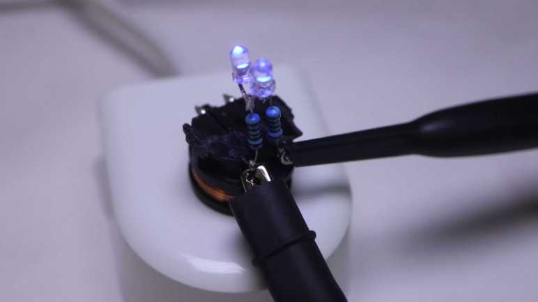
What’s the first step when exploring any electronic concept? Make it light some LEDs! Since this is an AC waveform, I soldered two salvaged LEDs side by side with opposite terminals.
When given DC power from my bench power supply, only one of the two LEDs would illuminate. If I reverse the polarity, the other LED would light up.
I didn’t bother with electrical connectors this time: the test LED assembly was soldered directly to coil terminals.
I put it on the charging base and both LEDs lit up, the expected response to AC power.
I connected my oscilloscope probes to see how the waveform changed with this load added to the system.
I can see a bump at roughly +/- 3.7V, the voltage drop point for these little blue LEDs.
That wraps a successful first test of using inductive power. Where might things go from here? If I can find the rectifiers I bought for the brushless motor generator experiment, I can get some amount of DC power flowing. It won’t be much power, a good chunk less than the 1.4W this charging base drew from the wall socket due to inductive power transmission losses. For comparison, slow USB charging is 5V @ 500mA or 2.5W, and that doesn’t even have to deal with inductive transmission losses. So any project idea would either have to be a modestly powered system or incorporate a battery like a Sonicare.
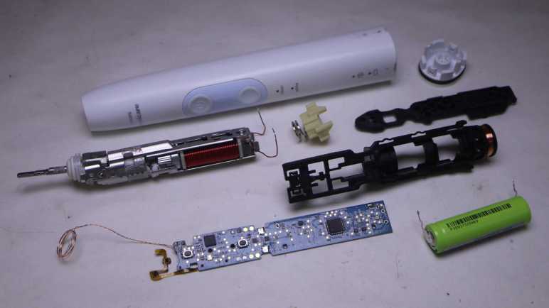
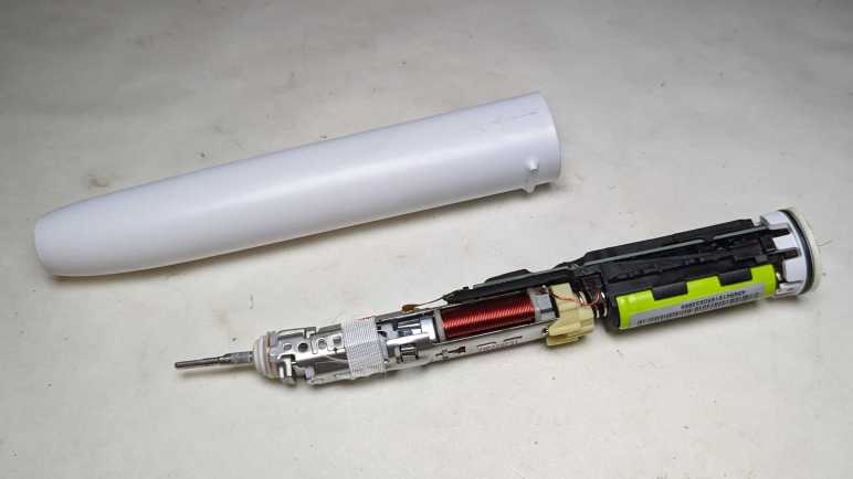
After looking over the electronics of my retired Philips Sonicare HX686P electric toothbrush, I unsoldered the main circuit board from the actuator, battery, and charging coil so I could remove it from the black plastic chassis.
Separating the main circuit board from the rest of the device also meant I could get good pictures both front and back.
I was surprised to see that there were a handful of surface-mounted components on the back. They couldn’t fit everything on one side.
The “pressing too hard” sensor’s flexible printed circuit strip is directly soldered to the back of the main board. I see ten soldering points, two per wire except for the left-most where four of them are connected to a single wire. This is consistent with power/ground/clock/data or some similar variation thereof.
On my previous Sonicare HX6530 teardown, my next step was taking the brush motor actuator apart. It was an instructive process, but a destructive one. Since the actuator in this HX686P is nearly identical, I doubt I’ll learn much from taking this one apart. It’s also in better shape, as it lacks the rust and deposits of water intrusion. I can keep it intact while hoping a project idea would arise. What would I do with it? I’m not sure! Recently, Hackaday featured somebody turning their old electric toothbrush into a tiny sander. The Hackaday writer Al Williams correctly pointed out this control board has a lot of features unsuitable to sanding. For example each session only runs for two minutes, with a small beep every 30 seconds. If we want to run it as a sander, we might be better off building our own control circuit for the actuator.
Sander or not, reusing the actuator will be best done with my own control circuit. I don’t know how to do that, but maybe this is a good opportunity to learn! I now have components on hand to support such a learning exploration: circuit boards with existing implementation, a disassembled actuator where I can test the coil by itself, and I have an intact actuator for potential application. And any knowledge I gain could continue to be useful in the future, because I’m still using a Sonicare every evening for my dental hygiene routine and it’s just a matter of time before I have additional retired toothbrushes to play with. Toothbrushes, and their associated charging bases.
I got inside my retired Philips Sonicare HX686P electric toothbrush and found a few physical signs of new features relative to my older Sonicare HX6530. Mechanically they seemed quite similar, but there’s a significant upgrade in electronics between the two.
Here’s the circuit board I pulled from the older HX6530, featuring a few surface-mounted components and even a few unpopulated positions, presumably to support features absent in this model.
And here is the newer HX686P circuit board. They are both the same length and have the same maximum width, but the older HX6530 board is a trapezoid that tapers versus a full rectangle in the newer HX686P. As a result the newer HX686P board has more surface area. It also has more surface mount components on board, packed more densely. There were no obvious unpopulated positions, but there’s at least one extraneous LED presumably to support feature absent in this model.
The ringleader of the new circus is a Cypress Semiconductor (since acquired by Infineon) CY8C4146AZI-S433, an ARM Cortex-M0+ microcontroller that offers a significant step up in computing power over a PIC16F726 used in the older HX6530.
The second largest chip on this board is a NXP MFRC630 for RFID applications. It makes sense it is positioned close to where the RFID antenna coil wires are soldered to the board.
Curious about what the chip is doing, I connected my oscilloscope to the RFID antenna wires where I could confirm… yep, something is happening. Beyond that, I don’t know what to look for or how to set my oscilloscope to be more informative.
Adjacent to the actuator electromagnet coil wires are these two tiny chips I inferred to be transistors controlling coil power. If so, they would be a counterpart to the Alpha & Omega Semiconductor field effect transistors found in the older HX6530 doing the same job yet only about a quarter of the size. Chip at position Q103 is marked 1Z W9n and chip at position Q104 is marked 1V W9n. There’s not enough room on these tiny chip to have full brand name and model number so this is an abbreviation. A web search on these designations turned up many results, but I couldn’t find anything relevant.
Adjacent to those are three white LEDs at position CR5, CR6, and CR7. Curiously, the external enclosure only had provision to show CR5 (“clean”) and CR6 (“white”) with only a smooth surface where CR7 would be. I never saw it illuminated, yet it was populated on this board during assembly.
The chip at position U2 is the third largest on this circuit board and has the abbreviation DEK 735. Another abbreviation I couldn’t find relevant information about.
The item at position F100 is in series with battery positive Vbat+ and labeled with just a single letter P. There is a very similar counterpart on the HX6530 board and I think they’re safety fuses. Perhaps P stands for polyfuse?
Near the charging coil (JC1 and JC2) and battery negative Vbat- are a pair of dual LEDs, each package contains a green and an orange LED side by side. These are used to indicate battery charging status (CR1) and notification for brush replacement (CR2).
It’s difficult to focus on the LED internals, here was my best effort.
And here’s the same item with the green LED illuminated. I want to get sharp pictures of these things, time will tell if that desire separates me from my money for a microscope camera.
I soldered wires to pads labeled SPDAT, SPCLK, Rx, and Tx so I could look at their activity under the oscilloscope. Rx stayed at the ground plane, while SPDAT, SPCLK, and Tx stayed at Vbat+ voltage level. I struck out again here, Sonicare firmware engineers are clearly not in the habit of shipping chatty hardware.
And finally, here’s a closeup shot of the chip I hypothesized was a brush actuator feedback sensor, sitting as it was over the gap between the electromagnet and permanent magnet. Perhaps it is a Hall effect sensor? Accelerometer? Audio microphone? There are many possible ways to measure actuator behavior, but again I struck out here. A search on its markings C180 1371G returned a lot of search results on Cessna 180 airplanes and Mercedes-Benz C-class automobiles, burying any information that might be relevant to a Sonicare toothbrush.
That’s what I’ve learned from poking around a disassembled Sonicare HX686P. What’s next?
I retired & took apart my Philips Sonicare HX6530 after it had slowly degraded over years. So slowly I didn’t realize until I was reminded by a newer unit: “Hey, this is what a Sonicare clean should feel like!”
I replaced it with this HX686P, which has also been recently retired due to degradation. But this one degraded overnight instead of gradually. Literally: one evening it felt fine, the next night “hey, what’s wrong with this thing?” My first thought was that I had accidentally triggered the “Easy-Start” feature, which introduced newcomers to Sonicare clean by starting easy and ramping up strength over time. I verified Easy-Start was not active, and ran out of ideas on why it might have suddenly weakened. Oh well, time for a new one and tearing down this one.
The manual for this HX686P explicitly stated it can be disassembled for battery disposal so I tried pushing on the metal toothbrush stem. Unlike attempts with the HX6530, I was successful popping this core loose. In addition to seeing if I can find any obvious signs of why it failed, I’ll be looking for physical implementation of some new features:
It works with newer brush heads to keep a usage count and notifying me when it’s time to replace the brush.
It detects when we’re pushing too hard for effective brushing, telling us to back off.
Comparing HX686P and HX6530 side by side, the mechanical components appear nearly identical.
There’s a loop of fiber-reinforced tape that would be useless for holding the metal assembly in place. I think it exists to hold the RFID antenna wire.
Peeling off the tape confirms there isn’t anything else underneath other than the RFID antenna wire. It also confirms the clips + welded system is still here. When I saw the welds on the old HX6530 I had wondered if it was a hack on top of an original clip-based design. Since it’s still here after several generations, I assume clips+weld is a belt-and-suspenders system to hold the mechanical actuator chassis together.
Here’s the other end of the RFID counter system, at the base of the brush head.
It was glued in place and impossible to remove non-destrutively, so I destroyed an old brush head for a closer look. The small chip is connected to a coil of wire that would sit aligned with the coil visible inside the toothbrush handle. I’ve read that people have tried to reverse-engineer this system.
Relative to the older Sonicare, another new component is this chip and capacitor sitting on a little segment of flexible printed circuit. Why are they here and what are they doing?
A hypothesis surfaced when looking at the side view: this chip is sitting above the gap between the electromagnet and permanent magnet, ideally placed to sense brush actuator lever motion. I think this is a sensor that feeds into the “is the user pushing too hard on the brush?” feature. To test this hypothesis, I peeled off the sensor which was held by double-sided tape. Once it was bent away, the “pushing too hard” alarm feature stopped working.
Another observation: The gap is noticeably larger here on the HX686P than on the older HX6530, but I’m not sure if that signified anything. On the other hand, the lack of water intrusion is certainly a good thing.
Until I decide to start destructively cut things away, I could only lift the circuit board a tiny bit. Peeking underneath, I don’t see any signs of a connector for the flexible board implying it’s soldered directly to the bottom of the circuit board. Before I try to get a better look at the bottom, there are plenty of interesting things up top.
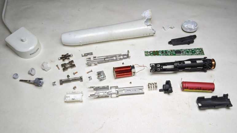
After looking over the circuit board and charging coil of my retired Sonicare (HX6530) electric toothbrush, only the electromechanical actuator assembly remains. Earlier in this teardown I noticed a few welds, that’ll have to be dealt with at some point, but I’ll start with the screws at the base of the electromagnet.
There were two of them, one top and one bottom. Removing the first one was undramatic. As soon as I loosened the second, though, there was a metallic “click” and it took me a few seconds to figure out what happened: as soon as the screws were loose, the electromagnet core slid up against the permanent magnet.
Manually prying them apart, I see the gap adjustment ranges from a maximum of almost two millimeters down to no gap which was where it went when the screws were loosened. This distance would affect toothbrush performance but I don’t know in what ways, so I have no idea how to optimize this gap.
Here’s a picture taken earlier intended to show rust as sign of water intrusion, but here we can also see the original spacing between permanent magnet and electromagnet. That is a tiny gap and I doubt I could restore that precise distance again. Then again, perhaps this distance is wrong: maybe its gradual degradation of performance was due to the electromagnet slowly sliding towards the permanent magnet over many years? Ignorant of metrics to measure proper operation, I have no way to tell.
On the other end of the actuator, I could access a single screw. Loosening it freed the toothbrush stem assembly, caked with deposit left from water that got past the rubber seal.
Everything else was enclosed inside the stamped sheet metal shell held with stamped clips as well as spot welds. I’m curious if it was originally designed to be held with just the clips. The welds may have been added to the manufacturing process later when they realized the clips along weren’t strong enough, or maybe the welds were part of the plan all along.
A cutting wheel removed the welds, but the stamped clips were pretty strong even without them. I ended up cutting off one set of clips as well.
Once the top and bottom stamped sheet metal bits could be separated, I could extract the electromagnet and the pivoting lever sub-assembly.
Unscrewing the visible fastener freed the permanent magnet from the pivoting lever sub-assembly. The final fastener was hidden under the top plate of the pivoting lever sub-assembly, holding it together. Once undone, everything could come apart.
This was a lot more complex than I had expected. Once I saw this device worked by using an electromagnet to actuate a lever, I expected an one-piece arm with a magnet on one side and the toothbrush head on the other. I infer this complexity was required because they wanted to implement a very specific motion profile for optimal dental hygiene. All these parts allow them to fine-tune the motion: from changing the thickness of spring steel plates to increasing/decreasing the mass at either end of the lever. If they wanted to optimize production costs, it wouldn’t need this much complexity to just vibrate a brush head. A cheaper and simpler knockoff could vibrate but not necessarily replicate the precise motion.
Would I notice the difference between a genuine Philips Sonicare and some cheap knockoff? Maybe yes, but maybe not alone by itself. I think I’ll notice a difference with a side-by-side comparison. After using Sonicare for years, I think I have a good idea of what feels right. While a slight gradual degradation may go unnoticed as was the case with this unit, if something goes wrong overnight I’ll notice. I’m confident because that happened with my next Sonicare.