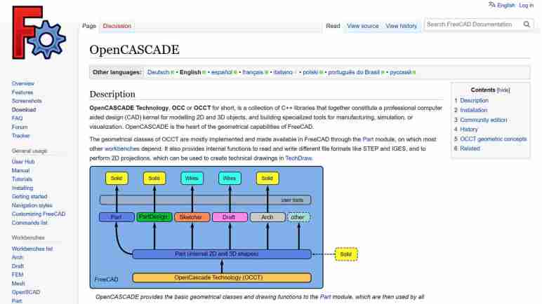
I’ve decided to spend some time learning about FreeCAD and was quite intrigued by their wiki page on OpenCascade (a.k.a. OpenCASCADE, OCC, OCCT, etc.) The first paragraph ended with “OpenCASCADE is the heart of the geometrical capabilities of FreeCAD.” The rest of the page goes into details on how OCCT integrated into FreeCAD code base and basic geometric concepts from which FreeCAD bodies are built upon. From this page I inferred that OCCT implements most (all?) of the basic requirements of building any 3D CAD software. FreeCAD can then be viewed as a set of user interfaces on top of OCCT concepts. Of course, this grossly understates the effort required to do such a thing but is a rough imperfect lens for this beginner to view the rest of FreeCAD through.
Elsewhere in FreeCAD documentation, I learned user interfaces are built around the concept of grouping related tools together. Each of these groups is a workbench intended to address their target usage scenarios. Despite their differences in methods operation, in the vast majority of cases, they all eventually break down to 2D or 3D elements built using OCCT primitives and manipulated via OCCT operations.
This is very interesting because, as an open-source CAD kernel, OCCT is not exclusive to FreeCAD. This means anyone who wants to try out a new twist on CAD semantics, they do not have to reinvent the wheel. They can build on top of OCCT as well. This sounded very interesting because one of my favorite features of Onshape CAD is that it is available anywhere that can run a modern web browser. I remember when “CAD workstation” meant a multi-thousand-dollar computer. With Onshape, a $200 Chromebook can be a modern CAD workstation.
This is not possible in FreeCAD, which is very solidly tied to a desktop. I think it would be very interesting to have an open-source browser-based CAD solution on top of OCCT, and I’m not the first to have this idea. I took a quick survey of several options, starting with CadQuery.
Creating Sawppy the Rover was a great learning experience, sharing it with the world was even more so. It wasn’t until I started receiving feedback that I learned tools for hardware projects lag behind the software world in their ability to support an open-source community. I published a wishlist earlier but haven’t made any progress on finding answers. But I know FreeCAD is going to come up in some way. FreeCAD is a large and high-profile open-source CAD project. It will either be part of the solution, or I will need to know it well enough to articulate why it isn’t.
Since I had always intended for Sawppy to be open-source, I looked into FreeCAD from the start. Back then, even people behind the project cautioned it was yet ready for prime time, so I took their advice and looked elsewhere. A few years later, FreeCAD release 0.19 close coincided with Autodesk starting to… shall we say… “aggressively increase revenue” from Fusion 360 users. This caused dissatisfaction within my maker circles. Some people took another look at FreeCAD and reported: “It’s not as bad as it used to be!”
That was hardly a ringing endorsement, but enough for me to take another brief look. My problem at the time was that 0.19 was hot off the press and all the available resources online were for 0.18 or earlier. And since FreeCAD 0.19 changed significantly, those resources were out of date. I made a mental note to come back later.
As of this writing in July 2023, the latest stable release of FreeCAD is 0.20 which was released June 2022. I expect a year’s time is enough for online resources to be aligned with 0.20 and thought I should give it another look. I started reading documentation and encountered a lot of unfamiliar terminology. This is normal whenever I venture into any new technical field, though it does slow down my reading a lot as I looked up definition for each.
I quickly got distracted by a specific acronym: OCC which stands for Open Cascade. (Also OCCT, for Open Cascade Technology.) It is the beating heart of 3D geometry math at the core of FreeCAD. Learning about OCCT opened my eyes to possibilities beyond FreeCAD.
I recently learned about a particular bit of engineering behind AHEAD (“Advanced Hit Efficiency and Destruction”) ammunition, and I was impressed. It came up as part of worldwide social media spectating on the currently ongoing Russian invasion of Ukraine. History books will note it as the first “drone war”, with both sides using uncrewed aircraft of all sizes for both strike (bombing) and reconnaissance (spying). Militaries around the world are taking notes on how they’d use this technology for their own purposes and deny the enemy use of theirs. “Deny” in this context ranges anywhere from electronic jamming to physically shooting them down.
“Just shoot them down” is actually a lot easier said than done, especially for small cheap multirotor aircraft like the DJI Mavic line widely used across the front. They have a radio range of several kilometers carrying high resolution cameras that can see kilometers further. Shooting anti-aircraft missiles to take them down is a financial loss: the quadcopter cost a few thousand US dollars, far less than the missile. And that’s if the missile even works: most missiles are designed to go against much larger targets and have difficulty against tiny drones. Every failed shot caught on camera gets turned into propaganda.
When missiles are too expensive, the classic solution is to use guns to throw chunks of metal at it. But since these are tiny drones flying several kilometers away, it’s nearly impossible to hit them with a single stream of bullets. The classic solution to that problem is to use some sort of scatter-shot. A shotgun won’t work over multi-kilometer distances (skeet shooting uses shotguns at a distance of a few tens of meters) so the answer is some sort of airburst ammunition: cannon shells that fly most of the way as an aerodynamic single piece then explode into tiny pieces, hoping to hit the target with some fragments.
OK great, but when should the shell burst apart? “Have it look for the drone!” is a nonstarter: even if something smart enough to detect a drone can be miniaturized to fit, it would be far more expensive than a dumb shell. The cheap solution is a timer: modern technology can make very accurate and precise timers, durable enough to be fired out of a cannon, at low cost.
It’s pretty easy to set a timer before the shell is fired, but what do we set the timer to? If it detonates too early, the fragments disperse too much to take down the target. Detonating too late is… well… too late. If the shooting cannon has a radar to know the distance to target, in theory we could divide distance by speed to calculate a time. But what speed do we use in that math? Due to normal manufacturing tolerances, each cannon shell will be a tiny bit faster or slower relative to another. Narrowing the range of tolerance is possible but expensive, opposite of the desire for cheap shells. It’d be nice to have a system that can automatically compensate for the corresponding variation.
Enter AHEAD. It removes one uncertainty by measuring the velocity of each shell as it is fired then sets the timer after that. Two coils just past the end of the barrel can sense the projectile as it flies past. Its actual velocity is calculated from the time it took for the shell to go from one coil to the next. That information feeds into calculation for the desired timer countdown. (A little more sophisticated than distance divided by velocity due to aerodynamic drag and other factors.) Then a third coil wirelessly communicates with the shell (which, as a reminder, has already left the barrel) telling it when to scatter into tiny pieces.
It shows the three coils in red: two smaller velocity measurement coils followed by the larger inductive timer programming coil. Given the 35mm diameter of the shell, there seems to be roughly 100mm between the two velocity measurement coils. Wikipedia page for an AHEAD-capable weapon lists the muzzle velocity around 1050 meters per second, which calculates out to ~95 nanoseconds to cover the distance between those two coils. The length of the shell is a little over five times the diameter, and the inductive communication coil is somewhere towards the back so call it 5*35 = 175mm from tip of shell to inductive coil. The distance from second velocity coil to programming coil is roughly the diameter of the shell at 35mm. 175 + 35 = ~210mm distance. That implies in the neighborhood of 200 nanoseconds from the time the tip clears the second coil, to the time the two inductive communication coils line up. That 200ns is my rough guess as to the time window for the computer to perform its ballistic calculations and generate a timer value ready to transmit. That transmission itself must take place within some tens of nanoseconds, before the communication coils separate. That is not a lot of time, but evidently within the capability of modern electronics.
Here’s a YouTube video clip from a demonstration of an AHEAD-armed system firing against a swarm of eight drones. Since it’s a sales pitch, it’s no surprise all eight drones fell from the sky. But for me, the most telling camera viewpoint was towards the end, when it showed the intercept from a top-down camera view. We can see the airburst pattern to the left of the screen and the target swarm to the right. From this viewpoint, the top-down variation is due to aerodynamic and other effects and the left-right variation is due to shell-to-shell variation plus aerodynamic and other effects. To my eyes, the airbursts are in a circle, which I inferred to mean the system successfully compensated for shell-to-shell variation.
I’m not very knowledgeable about military hardware so I don’t know how this system measures up against other competitors for military budgets. But from a mechanical and electronics engineering perspective I was very impressed there is a way to set the fuze timer after the shell has been fired.
I’ve got a set of inexpensive load cells hooked up to log signs whether I’m getting a good night’s sleep. It was an experiment that was both interesting to me and fits within the quite-significant limitations of these cheap little things. I’m going to leave that setup collecting data for a while, in the meantime I want to write down details on the software side before I forget.
I did not try to compensate for temperature or for system warmup, those two together could affect final weight output by as much as half a kilogram. But in the specific purpose of tracking changes on a minute-by-minute basis, those factors could be ignored.
This sensor and HX711 amplifier combination has a recurring issue sending occasional readings that do not reflect what’s actually happening. To minimize effect of these spurious data points, I have taken the following measures:
The reported weight value is the median weight out of the past minute and a half. Median value filter is more tolerant of spurious data of drastically different values.
Once I had everything set up, I noted the minimum measured value (empty bed) and the maximum expected value (bed with me in it) and discarded all values outside of that range as “Off Scale Low” and “Off Scale High”. That will throw out some spurious data but still leaves those within the expected range.
The reported delta value is not the difference between the maximum and minimum values seen within a time window. I track the second-largest and second-smallest values and report that delta instead. This way I can ignore spurious outliers, though it only works as long as spurious data doesn’t happen multiple times within a minute. Fortunately that’s been the case so far. If the problem gets worse I’ll have to devise something else.
And here’s the ESPHome YAML. If you want to copy/paste this code, feel free to do so. But make sure the values of hx711 “dout_pin” and “clk_pin” matches your hardware. The constants used to filter off-scale high/low will also need to be adjusted to fit your setup:
sensor:
  - platform: template
    name: "Delta"
    id: load_cell_delta
    accuracy_decimals: 0
    update_interval: never # updates only from code, no auto-updates
  - platform: template
    name: "Off Scale Low"
    id: load_cell_toolow
    accuracy_decimals: 0
    update_interval: never # updates only from code, no auto-updates
  - platform: template
    name: "Off Scale High"
    id: load_cell_toohigh
    accuracy_decimals: 0
    update_interval: never # updates only from code, no auto-updates
  - platform: hx711
    name: "Filtered"
    dout_pin: D2
    clk_pin: D1
    gain: 128
    update_interval: 0.5s
    filters:
      median:
        window_size: 180
        send_every: 120
    on_raw_value:
      then:
        lambda: |-
          static int load_window = 0;
          static float load_max = 0.0;
          static float load_second_max = 0.0;
          static float load_min = 0.0;
          static float load_second_min = 0.0;

          // Ignore spurious readings that imply negative weight
          if (x > -500000) // Constant experimentally determined for each setup
          {
            id(load_cell_toolow).publish_state(x);
            return;
          }
          // Ignore spurious readings that exceed expected maximum weight
          if (x < -1500000) // Constant experimentally determined for each setup
          {
            id(load_cell_toohigh).publish_state(x);
            return;
          }

          // Reached the end of our min/max window, publish observed delta
          if (load_window++ > 120)
          {
            load_window = 0;

            // Use second largest/smallest values, in case the absolute
            // max/min were outliers.
            id(load_cell_delta).publish_state(load_second_max-load_second_min);
          }

          if (load_window == 1)
          {
            // Starting a new min/max window
            load_max = x;
            load_second_max = x;
            load_min = x;
            load_second_min = x;
          }
          else
          {
            // Update observations in min/max window
            if (x > load_max)
            {
              load_second_max = load_max;
              load_max = x;
            }
            if (x < load_min)
            {
              load_second_min = load_min;
              load_min = x;
            }
          }
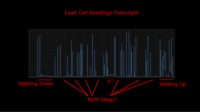
I took an inexpensive HX711-based load cell setup (the type that measures body weight in a bathroom scale) and installed them under my mattress. I wasn’t interested in measuring my weight while I sleep, I was interested in changes that indicate movement while sleeping. Ideally, I would see pauses in the data implying muscle inhibition associated rapid-eye movement (REM) sleep. I would take lack of movement as an indication of restful sleep. Logged to my Home Assistant database, here’s a plot of first night’s data:
This was a relatively restful night where I woke up refreshed. Looking at the plot, I can see when I got into bed and muscle activity gradually reducing as I fell asleep. There are multiple periods of nearly zero movement, implying a nice deep sleep in my cycle. As I started waking up in the morning, the load cell picked up more activity.
There was one unexplained set of data halfway through the night, where the movement activity is low but not as low as restful periods. The movement resembled my “settling down” period. I wonder if I woke up for some reason and had to fall back asleep? If so, I have no memory of this.
For comparison, here’s a graph of a different night’s data:
It was not a restful night of sleep. I have vague memories of waking up in the middle of the night, tossing and turning. I also woke up exhausted which corroborated with this plot of measured weight delta. It took longer before I fell asleep, there were far fewer periods of restful low movement, and I started to stir much earlier before I got out of bed.
I’ll keep the system running for a while, logging information from a time when I’m asleep and unconscious. But that’s about as far as I’m going to go. It would take more sleep science knowledge to analyze this data further and I’m not inclined to do so. Partially because this was a really cheap load cell + HX711 amplifier chip combo delivering unreliable data. Some of these “movements” may just be spurious data from the sensor. I wouldn’t read too much further into it, it’s just a fun project and not a serious health diagnosis tool. But here’s my ESPHome/HX711 code if anyone wants to play with it.
I didn’t expect a lot when I paid less than $10 for a set of load cells from Amazon, and indeed it has some pretty significant limitations. But that’s fine, every instrument has limitations and it’s a matter of making sure an application fit within them. Looking at the limitations of this sensor, I thought I had the perfect project fit: use them to gain some insight on my sleep quality.
Quality of sleep is important and there’s a lot of research behind it. For the home scientist, one of the easiest metrics to measure is the fraction of time we stay still in rapid-eye movement (REM) sleep. Problems disrupting sleep will cut into the amount of time we spend in REM sleep, depriving our brains of an important part of resting. Measuring actual eye movement is difficult, but (healthy) REM sleep also temporarily inhibits our muscles keeping our body still. This is an imperfect correlation: it is possible for muscle movements to happen while in REM sleep (should be small, though) and it is possible to stay still without being in REM sleep. Despite the imperfection, sleep movement is a good proxy.
There are many options to track sleep movement in the consumer medical technology field. Health wearables with accelerometers can do it, but it requires wearing the device while sleeping. Alternatives to wearing something include motion-detection cameras, but I’m not putting a camera in my bedroom. Using a set of cheap load cells seems like a good option, and logging data to my Home Assistant server at home is much better for personal privacy than a cloud-based solution.
I’ve already written my ESPHome YAML lambda tracking maximum/minimum values within a one-minute window. It was originally intended to quantify noise inherent in the system, but it works just as well to pick up changes on sensor readings. So, there will be no additional software work required.
On the hardware side, I have an IKEA bed frame with a series of slats holding up the mattress. I can put my sensors where the slat rests on the frame.
Load on all other slat-frame interface is not measured, which meant the absolute measured values will change depending on where my body is on the bed. Fortunately, the absolute value doesn’t matter because I’m only interested in changes minute-to-minute. Those changes over time are my sleep movement data. This also means I can ignore other problems with this instrument’s absolute values, like system warmup and daily temperature cycle sensitivity.
The bad news is the problem of spurious data will still impact this application. Such erroneous data will indicate movement when no actual movement has occurred. It means these measurements will understate the quality of my sleep by some unknown amount. (I slept better than the data indicated, but by how much?) However, given that the correlation between REM sleep and lack of motion is an imperfect one to begin with, perhaps this error is acceptable. The recorded data is pretty noisy but some patterns are visible.
I dusted off my inexpensive load cell system (read by a HX711 chip) and switched the associated microcontroller from an Arduino Nano to an ESP8266. That ESP8266 was then programmed using ESPHome to upload load cell readings to my Home Assistant server. I configured the ESP8266 to read every half second, but I’ve learned sending that much raw data directly to Home Assistant bogs down the system so that twice-a-second data is filtered to a summary report once a minute.
General Noise
One summary is generated by a small code snippet I wrote tracking the difference between maximum and minimum values seen within that minute. This gives me an idea of the natural level of noise in my particular configuration. If all other variables are unchanged, I saw a fluctuation of roughly 350 sensor counts, mostly within the range from 250 to 450.
The other summary is an average. Since I already had code tracking maximum and minimum, it wouldn’t have been hard to calculate my own average. But rather than adding those 3-5 lines of code, I used ESPHome’s built-in sliding window moving average filter because it was already there. Keeping the system running for a little over 24 hours, here’s the graph it generated:
Spurious Data
The little spikes visible in this graph are caused by the occasional data that does not reflect reality. I saw this in my earlier experiments with the HX711 talking to Node-RED, but that only ran for a few minutes at a time. I had hoped that, by graphing its behavior over a day, I could observe some pattern.
There was no frequency-based pattern I could detect: they can happen mere minutes apart, and sometimes I can go for hours without one.
I only have a single day, which is not enough data to say if there’s a time-of-day pattern.
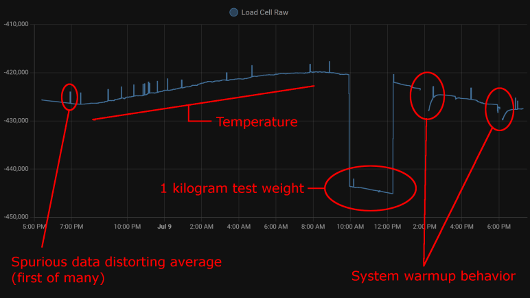
Visible spikes in the graph were caused by nonsensical values indicating less weight than when the load cell is completely unloaded: negative weight, so to speak. The raw sensor count is usually in the few thousands range when unloaded is approximately -420,000, a big enough difference to visibly throw off the average over 120 readings.
Even though “negative weight” is the most visible in this graph, there are also unexplained brief flashes of data in the positive weight domain, they just don’t throw off the average value as visibly on this plot.
Temperature Sensitivity
One behavior I never noticed during my short duration Node-RED experiments were the relation between sensor counts and temperature. With a full day’s worth of data plotted, the correlation is clearly visible. From around 7PM to 8AM the next day, temperature dropped from 28.2°C to 21.6°C. (Tracked elsewhere in my Home Assistant network, not on this graph.) During this 6.6°C drop, average sensor count rose from around -426,500 to -420,000. This rounds to approximately 1000 sensor counts per degree Celsius.
Kilogram Test
But what do those sensor counts correspond to? I used my kitchen scale to measure as I poured water into a jar, stopping when they weighed one kilogram together. I placed that on my test setup for two hours. This dropped sensor counts from around -420,000 to -443,000 (plus temperature-induced variation). Using 23,000 sensor counts per kilogram, I can tentatively guess the random noise of ~300 sensor counts correspond to roughly thirteen grams. This is consistent with my earlier observation I need roughly fifteen grams of weight change before it is barely distinguishable from noise.
By the same metric, temperature change for a single degree Celsius changes the reading by roughly 43 grams. Over the course of a day that varies by 6.6 degrees Celsius, that would change weight reading by roughly 280 grams.
System Warmup
I brainstormed on possible reasons for spurious data and thought perhaps they were caused by the JST-XH connectors I used. A small intermittent connection might not be noticed in most of my projects, but load cells work by slight changes in resistance and the HX711 amplifies those changes. Small flaws in a connector that would go unnoticed elsewhere would drastically change behavior here, so I unsoldered the connector and soldered all wires directly to the HX711 board.
That experiment was a bust, direct soldering did not eliminate spurious data. I still don’t know where that’s coming from. But I came out of it with an additional observation: When I disconnect the system for a while to work on it, then turn it back on, there’s a warmup curve visible on the plot. This graph had two such work sessions, and I see a curve of roughly 3000 sensor counts. That’s roughly 130 grams.
Conclusion
Based on these observations, I conclude this specific load cell setup is only dependable down to about half a kilogram before we have to worry about compensating for factors system warmup or ambient temperature. This is consistent with the primary use of these devices: inexpensive bathroom scales for measuring human body weight.
We also need to account for spurious data in some way, for example take multiple readings and average them, possibly ignoring readings that are wildly inconsistent with the rest.
And even if we somehow managed to compensate for environment variables, it’s not possible to reliably measure any changes less than ~20 grams because of fundamental noise in this system.
This isn’t bad for a $10 kit, but its limitations does constrain usefulness. After a bit of thought, I think I have a good project idea to fit this sensor.
A few years ago, I bought a cheap set of load cells to play with. The kind that performs weight measurement in an inexpensive bathroom scale. I got them up and running with the bundled HX711 board, sending data to Node-RED. Using this infrastructure, I performed a silly little (but interesting!) experiment measuring squishing behavior of packing material. I then got distracted with other Node-RED explorations and haven’t done anything with the HX711 load cell setup since. Now I’m going to dust it off (quite literally) and play with it again. This time, instead of Node-RED, I’ll be using the ESPHome + Home Assistant infrastructure.
There are multiple reasons for this switch. After a few experiments with Node-RED, I haven’t found it to be a good fit for the way I think. I like the promise of flow-based programming, and I like Node-RED’s implementation of the idea, but I have yet to find enough of an advantage to justify changing over. Node-RED promised to make prototyping fast, but I found something that got my prototypes up and running even quicker: ESPHome and Home Assistant. In my experiments to date, ESPHome’s YAML-based configuration lets me get simple straightforward components up and running even more quickly than I ever managed under Node-RED. And when I need to venture beyond the simple defaults, I can embed small fragments of C code to do just the special thing I need. This comes to me more naturally than using Node-RED’s counterpart function node with a snippet of JavaScript. It’s also very quick to put together simple UI using Home Assistant, though admittedly with far less control over layout than Node-RED’s dashboard.
But the primary motivation this time around is that I already had an instance of Home Assistant running, so I don’t need to set up logging infrastructure for longer-duration projects. Node-RED is perfectly capable of working with a database, of course, but I’d have to set something up. Home Assistant already has one built-in. By default, it stores data only locally, and only for ten days, making it much more privacy-friendly than internet-based solutions with wildly varying levels of respect for privacy.
Hardware changeover was pretty simple. The HX711 board needed four wires: power, ground, data, and clock. I unsoldered the Arduino Nano I previously installed and replaced it with an ESP8266. It will need to run ESPHome’s HX711 integration, which under the hood used the same PlatformIO library I had used earlier for the Arduino Nano. A few lines of YAML later, load cell data started streaming to my Home Assistant server for me to examine.
Moving my RXBB8 project website from AWS to GitHub Pages has another benefit: now it is trivially simple to update. I push a change, and GitHub default Action will handle publishing. Much easier than copying the files over to an AWS S3 Bucket like I had to do earlier. Which means it is a great time to make (what’s very likely) the final update to this project site.
First, I updated the content of the page, adding a shorter version of what I’ve posted earlier: Why I decided to say goodbye to RXBB8, and then the process of actually doing so. Illustrated with the same image files I used here. I decided against following the precedence of providing a “web” (low resolution) and “full” (high resolution) copies of each image. For this final update, I’m providing only the web resolution image. Previous content is largely untouched except for one point: instead of link to “latest activity” on social media Facebook and Instagram, I updated it to be past tense and added Twitter as well.
After the content was updated, I updated the behind-the-scenes infrastructure as well. I had used the Materialize-CSS library for this project, and I thought I would be six years out of date. (Fortunately given it is a static site, the chances of a dangerous security flaw are quite low.) Then I looked at Materialize-CSS library releases and realized I was only about a year out of date. The library reached version 1.0.0 on September 2018 at which point activity stopped. Since it is done I thought I should download the version 1.0.0 CSS and JavaScript files for direct inclusion on my site. There’s no longer any worry of falling out of date, but now there is the worry of the project distribution site disappearing.
Since I only used some superficial capabilities of the library, I did not expect anything to break and visually everything looks fine. I did notice one advancement, though: version 1.0.0 no longer depends on jQuery, so I removed the line loading jQuery from my page.
Is this the end of my interaction with Materialize-CSS? Maybe, maybe not. There’s a potential upside of a library frozen in 2018 at version 1.0.0: It probably still works on Windows Phone browser. I will likely revisit Materialize-CSS if I want to work with Windows Phone browser again. And even if the project site disappears, I have a copy of the library CSS and JavaScript now.
After peeling the BB-8 inspired art from my Mazda RX-8, it seems like a good time to do some long-overdue cleanup on the project site as well. Six years ago, I wasn’t sure whether it’s better to build a website for each project or just put everything here on a single personal blog. With experience, I now know my scatterbrained nature is a better fit for the latter. Also, domain registration costs add up quick!
I had created http://rxbb8.com to be a small static web site served via Amazon Web Services, and one of the earlier entries on this blog was an outline of my experience setting it up. What I have forgotten (and did not write down) was why I chose this approach as opposed to using GitHub Pages. I already had a GitHub repository for the markup files, though without the image files. I suspect there was something about GitHub policy six years ago that made it impractical. Was there a file size limit that prevented image files? Another data point was that project predated Microsoft acquiring GitHub which changed a lot of policies. Also, a lot of features were added to GitHub over these years. Is it possible GitHub pages didn’t exist at the time? I no longer remember.
What I do know is that I would like to move it off AWS now. Hosting this site via AWS has been quite affordable. Every month I pay $0.50 USD for the Route 53 name service and a few cents for S3 bandwidth. Historically that has added up to less than half of the domain registration itself, which was $18/yr via DreamHost. However, there’s a hidden risk on that S3 expense: there is no upper bound. If someone decides to write a script to repeatedly download all of my images as quickly as possible, my bill will go up accordingly and I won’t know until I see my bill next month. Sure, it’d cost them bandwidth as well, but most bandwidth are cheaper than S3 rates and that’s assuming they aren’t doing something unethical like consuming some innocent third party’s bandwidth. Six years ago, I dismissed such worry as “Nobody would have a reason to do that.” Now I am older and more cynical. The truth is all it’d take is for one person to decide “because I can” is a good enough reason and cause me grief.
In the time I’ve been learning web development, I’ve come across horror stories of unexpected AWS bills. Always inconvenient, sometimes it leads to people getting fired from their job, and occasionally a startup has to declare bankruptcy and shut down because they can’t pay their AWS bill surprise. Thinking about that possibility has me on edge and I have enough to worry about in my life. I don’t need that stress.
Another reason is to eliminate a recurring stream of nag mail. Setting up a static web site as I have done means setting an Amazon S3 bucket to be globally readable by everyone. This wasn’t a big deal six years ago but there have been multiple cases of people finding confidential data stored in publicly accessible S3 buckets. Because of this, public buckets are now rightly treated as potentially risky. So, Amazon sends periodic email reminding me I have a public bucket and to review that I’m really, really sure I wanted it that way. This is good security practice, but I have enough email spam. I don’t need another stream.
Now that I’ve finally gotten around to moving the site, my steps are:
Upload project image files to existing GitHub repository.
After waiting a day to ensure all DNS changes have propagated, I can deactivate my AWS Route 53 hosted zone and delete my AWS S3 bucket. With the new forwarding action, browser URL bar would visibly change to https://roger-random.github.io/rxbb8.com/ as well. I’m fine with that. If I really wanted to keep the URL bar at http://rxbb8.com, I can read up on how to use a custom domain with GitHub Pages. But right now, my priority is on making what is likely to be the final update to the site.
My RXBB8 project is looking pretty tired after six years, and I’ve decided it’s time to say goodbye and restore my 2004 Mazda RX-8 to its original factory blue. Removing a Plasti-Dip project involved several different distinct steps.
Large Surface Removal
The easiest part is the headline feature of Plasti-Dip: we can peel it off automotive paint. When applied thick enough, large sheets can be peeled off intact. My first full-car Plasti-Dip project only had three coats and it was annoying to remove. RXBB8 had six coats of white plus up to three additional coats for either orange, silver, or black. The hood was easiest to peel on account of its thick layer of Plasti-Dip, followed by the roof and trunk. Those were all horizontal surfaces where I was comfortable applying thick coats. I was afraid of drips on vertical surfaces, so doors and fenders didn’t get as thick of a coat and were correspondingly more difficult to peel off intact.
Ever heard “the first 90% of a project takes 10% of the time”? Removing Plasti-Dip is like that. My car was 90% back to its original blue very quickly, but removing the rest will take a lot more effort.
Edge Cleanup
As large surfaces were removed, they tend to leave fragments of their edges behind. I probably didn’t spray the edges as thickly as the middle, causing them to break apart and be left behind. And since they were already reluctant to leave, taking them off becomes time-consuming. Each of these two fragments took about as much time to cleanup as peeling majority of the bumper.
Overspray Cleanup
Beyond edge pieces lie overspray, super thin bits of Plasti-Dip that is not thick enough to become a peelable layer. Now I need to turn to chemical removal with solvents that can remove Plasti-Dip without damaging the underlying paint. (Or at least, not damage it too much.) I used Xylene, which was the recommended cleanup solvent six years ago, but there might be a better choice now.
In this picture I temporarily removed the rear window so I could reach all of the overspray underneath window edges. Some overspray is accessible without removing any parts, like the doorsill visible through this window.
Detail Cleanup
And finally, I have to pull out the box of Q-Tips so I can remove Plast-Dip that has worked their way into tiny little details. Overspray and detail cleanup is tedious, and I have to take frequent breaks because Xylene fumes are unpleasant even when working in a well-ventilated space.
The problem with detail cleanup is that it feels like a never-ending process. I tackle the most visible things first and when that is done, I take a step back to look for the next most visible area to clean. As I make progress, the “next most visible” area becomes harder and harder to clean. I don’t think I’m going to be able to get absolutely everything, and I have to be resigned to my car having little crooks and crannies of white and orange.
Around six years ago I decided to use Plasti-Dip to turn my 2004 Mazda RX-8 into a fan tribute to Star Wars BB-8 droid. This project titled RXBB8 was originally intended for a few months, but I loved it enough to keep it on my car for several years. Unfortunately, it has degraded enough I am ready to say goodbye.
No Cracks
Plasti-Dip sprays on as a liquid and dries to a rubbery layer that conforms to the sheetmetal curvature but does not adhere to the paint. That’s the beauty of it: I can peel it off when I’m done. Due to its soft texture, I had expected Plasti-Dip to degrade like all soft texture materials do under relentless Southern California sunshine: turn brittle and crack apart. I was pleasantly surprised to find that it had not done so after six years. It may be a little less stretchy than new, but it was still intact.
Minor Fade
Another failure point I had expected is color fading, another typical reaction for things under sunlight exposure. Plasti-Dip exceeded expectations here as well. I thought the silver parts would hold up but the bright orange to fade. While the color did fade over the years, it did so gradually. More importantly, it faded evenly so I didn’t end up with blotches of different shades of color.
Sharpie Ink Faded
The same could not be said of Sharpie permanent marker ink. For smaller scale details like the emblem and a thumbs-up BB-8 on the trunk, that’s what I used instead of Plasti-Dip. Marker art faded significantly and also faded unevenly so colors were blotchy. This is a lesson learned and I know not to rely on markers for this purpose in the future.
Embedded Dirt
And finally, the biggest reason I’ve decided to peel off RXBB8 is because it has become very difficult to keep clean. Because it is a relatively soft material exposed to road conditions, tiny grains of dirt could embed themselves into Plasti-Dip in a way I couldn’t wash off. Over years this buildup accumulated to the point the car looks dirty even after a good scrub. It is especially noticeable on white! When I had to admit to myself the car looks dirty no matter what I did, it’s time to say goodbye to RXBB8.
Administrative side note: This is the 2000th post of this blog. I learned a lot in my first 1000 posts and adapted my style accordingly. I haven’t changed my format for the next thousand as it’s been working pretty well for me.
I experimented with building a faux VFD effect on modern screens. Just a quick prototype without a lot of polish. Certainly not nearly as much as some other projects out there putting a retro look on modern screens. One of those I’ve been impressed with is cool-retro-term. (Mentioned as almost an aside in this Hackaday article about a mini PDP-11 project.) I installed it on my Ubuntu machine and was very amused to see a window pop up looking like an old school amber CRT computer monitor.
The amber color looks perfect, and the text received a coordinate transform to make the text area look like a curved surface. Not visible in a screenshot are bits of randomness added to the coordinate transform emulating the fact CRT pixels aren’t as precisely located as LCD pixels. There is also a slight visual flicker effect simulating CRT vertical refresh.
The detail I found most impressive is the fact effects aren’t limited to the “glass” area: there is even a slight reflection of text on the “bezel” area!
So how was all this done? Poking around the GitHub repository I think this was written using Qt native UI framework. Qt was something I had ambition to learn, but I’ve put more time into learning web development because of all the free online resources out there. I see a lot of files with the *.qml extension, indicating this is a newer way to create Qt interfaces: QML markup versus API calls from code. Looking around for something that looks like the core of emulating imperfect CRTs, the most promising candidate for a starting point is the file ShaderTerminal.qml. I see mentions of CRT visual attributes like static noise, curvature, flickering, and more.
It should be possible to make an online browser version of this effect. If the vertex shaders in cool-retro-term are too complex for WebGL, it should be possible to port them to WebGPU. Turning that theory into practice would require me to actually get proficient with WebGPU, and learn enough Qt to understand all the nuts and bolts of how cool-retro-term works so I can translate them. Given my to-do list of project ideas, this is unlikely to rise to the top unless some other motivation surfaces.
Tonight on my bike ride I saw a guy driving a real life Buick Reatta (in mint condition somehow) and at a stoplight i peeked in the window and it had the really cool dash displays like this pic.twitter.com/SLiMSLRoEi
I’ve played with a small VFD salvaged from an old video cassette machine, but that’s nothing like the panorama we see on a Reatta dashboard. It is not something we’re likely to see ever again. The age of VFDs have long since passed and it’s not practical for an average hobbyist to build their own. The circle of people who consider VFD retro cool is probably not big enough to restart VFD manufacturing. That leaves us with building fakes out of technology we have on hand, and I thought I could quickly prototype my idea using web technologies, and here it is:
There are two parts to this faux VFD.
Less obviously visible is the fine hexagonal mesh emulating the control grid I saw when I put my salvaged VFD under a macro lens. I believe it is one of the two electrodes, whether anode or cathode I do not know. But it is a subtle part of a VFD that designers put effort into reducing and masking. Now it is part of the VFD charm and I wanted to replicate it.
Since it is a pattern built out of many small repeating sections, I thought the best way to recreate this mesh is with a bit of JavaScript code drawing to a <canvas>. Otherwise, I would have to create it in markup and that means a lot of duplication in a massive markup file. The innermost section of the loop draws three lines 60 degrees apart, and the loop iterates across the entire display area. Using code to draw vector graphics (versus tiling a bitmap) make this grid dynamically scalable to different resolutions.
Rendered behind the mesh is the “content” of the VFD, which is just a simple circle in this case. Since this is a large feature likely to be subject to direct editing, I decided to do this in SVG markup. My first attempt didn’t look right: modern screens are far too clear and crisp compared to a VFD. Such clarity is useful to render the fine details of my hexagonal control grid, but not for the VFD phosphors. I looked around online and found a SVG blur filter which was a lot closer to how a VFD would look.
I know the result isn’t perfect and I don’t know if I would end up applying this experiment to a future project, but I really liked the fact I could whip up a quick prototype in less than an hour. And furthermore, be able to share the prototype online via infrastructure like CodePen. Even if I don’t end up using it myself, putting it online makes it available for someone else to take this idea further.
The reason I want to be able to read JavaScript code written by others, no matter what oddball syntax they want to use, is because I want to be able to leverage the huge selection of web development libraries available freely on the internet. I started learning software development in a very commercialized world where everything costs money. Frameworks, components, technical support, sometimes even documentation costs money. But in today’s open-source world, the biggest cost is the time spent getting up to speed. I want to have the skill to get up to speed quickly, but I’m definitely not there yet.
The latest motivation is a nifty looking web app framework under development called Arwes. (Heard through Hackaday.) Arwes aims to make it easy to build computer interfaces that resemble fictional interfaces we see in science-fiction movies. This is, of course, much easier said than done. What shows up onscreen in a movie typically only needed to serve the purpose of a single scene. Which means a single interaction path, with a single set of data, towards a single goal. It could easily be a PowerPoint slide deck (and sometimes that’s exactly what they are on set.)
Real user interfaces have to handle a wide range of interactions, with a wide range of data, and serving multiple possible tasks. Not to mention having to worry about things never seen onscreen like internationalization and accessibility. Trying to make Sci-Fi onscreen interfaces work in a real world capacity usually ends up as a painful exercise. I’ve seen many efforts to create UI resembling Star Trek: The Next Generation‘s LCARS interface and it always ends up as something that delivers a poor user experience and inefficient use of screen real estate. And there’s the fact copyright around LCARS prevents a free open-source web framework.
I’m confident Arwes will evolve to tackle these and other similar issues. Reading the current state of documentation, I see there exists a set of “Vanilla” controls for use in any web framework of choice, and a sample implementation of such integration with React.js framework. At the moment I don’t know enough to leverage the Vanilla controls directly, and I have yet to learn React. I have more learning ahead of me before I could look at a framework like Arwes and say: “Oh yeah, I know how to use that.” That is still my goal and I’ll get there one small step at a time.
I’ve had the opportunity to look at a lot of sample JavaScript code snippets as part of learning web development. For the most part I could follow along, even if I lacked the skill to create something new on my own. Due to its rather haphazard evolution, though, JavaScript does have an annoying habit of having many different ways to do the same thing. Part of this is past-looking historical: as browsers tried to merge different implementations into one globally compatible whole, everyone’s slightly different approaches had to remain valid for backwards compatibility. Part of this is future-looking cultural: well-meaning people try solving old problems by inventing something new intended to do everything the old stuff does “but better”. When combined with the need for backwards compatibility, such efforts meant we end up with the legendary XKCD “Standards”.
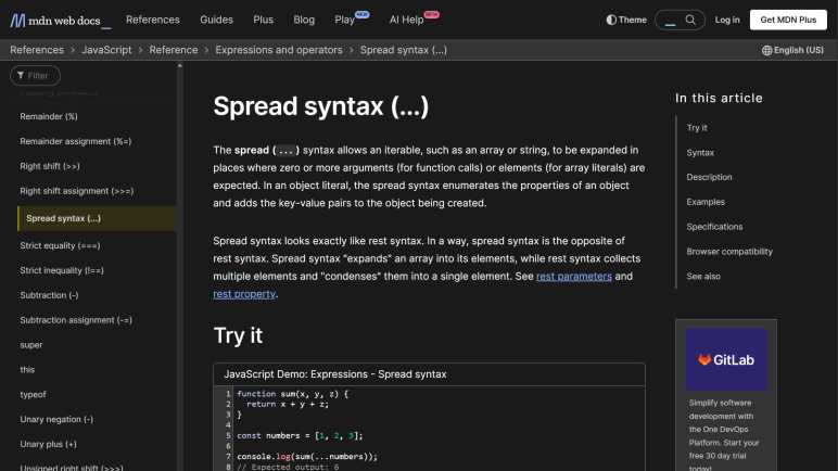
Particularly annoying to me are JavaScript syntax additions that are just about impossible to put through a search engine. They’re usually scattered around but I found a Medium post JavaScript’s Shorthand Syntax That Every Developer Should Know that was a pretty good roundup of every single one that had annoyed me. The author pitches these shorthand as enabling “futuristic, minimal, highly-readable, and clean source code!” And as a beginner, I disagree. They are opaque and unreadable to those that didn’t already know them and, due to their nature, it is very hard for newbies to figure out what they mean.
Take the first example: the spread syntax. When I first came across it, what I saw in the source code were three periods. That is not self-explanatory as to its function. This Medium post had a comparison example and touted spread syntax as much cleaner than Array.from(arguments) but I could search for “Array.from()” and “arguments” to learn what that does. Trying to search for “…” was a fruitless exercise in frustration that ended in tears because search engines just ignore “…” as their input. I did not know what the spread syntax was (or even that’s what it was called) thus I was up a creek without a paddle.
The rest of this Medium post covered:
Inline short-circuits and nullish coalescing. This uses “||” but any search hits would be buried under information about logical OR operation.
Exponential operator and assignment. This is “**” and “**=” which usually gets treated as accidental duplicate characters leading to information about “*” and “*=“.
Optional chaining via “?.” a series of punctuation marks who also get ignored by search engines just like “...“.
Non-decimal number representation is the least bad of this bunch, at least beginners have something to search with like “What does 0x10 mean in JavaScript”.
De-structuring and multiple assignment are the worst. There is literally nothing to put into a search engine. Not even an “...” or “?.” (which gets ignored anyway.) There’s no way for a beginner to tell the syntax would extract selected member values from a JavaScript object.
I can see the value of these JavaScript shorthand for creating terse code, but terse code is not the same as readable code. Even though I’m aware of these concepts now, every time I come across such shorthand I have to stop and think before I could understand the code. It becomes a big speed bump in my thought process, and I don’t like it. I certainly don’t feel it is more readable. However, I have to grudgingly agree the author’s title is true, just not in the way they meant it. They are JavaScript’s Shorthand Syntax That Every Developer Should Know because such code already exists, and every JavaScript developer need to know them well enough to understand code they come across.
I thought there was a good chance my cheap driving wheel setup would sit unused, given my history of buying such peripherals, but I’ve spent several hours in Forza Horizon 5 with my economy-class setup. Not yet enough to justify upgrading to more expensive hardware, but enough to start thinking about low-budget improvements. I’ve been using the wheel and pedal with my living room couch. The seat cushion is approximately the right height, but the seat back is too far back.
There are vendors out there selling racing simulation seats resembling those in real cars. Some people would actually skip the fakery and go to an auto salvage yard to get a seat from a real car. But I’m too cheap for even that approach, for my first draft I want to spend $0 and use what I already have.
I have an old IKEA chair that has been mostly gathering dust. The seat cushion height is too tall for the steering wheel. While the seat back distance is far better than the couch, it is a relatively upright seating position which is unlike what is found in sporting cars.
Since I had my hand saw (and sawdust cleanup tools) already out for messy teardown projects, I decided to cut down this chair’s legs. For the first draft I’ve taken 10cm off the front legs and, to lean back the seating angle, I took 12cm off the back.
It’s still a little higher than my couch cushion and still a pretty upright seating angle, but I want to try a small step before going further. It’s a lot easier to cut the legs shorter than it’d be to cut them longer.
If the changes are too subtle, here are the two pictures side by side.
The first trial run was promising. It is obviously not a real racing seat, and it is not comfortable enough for long endurance sessions. But that shouldn’t be a problem as I haven’t spent too much time in Forza Horizon‘s Mexico yet. So just like before: this cheapo setup will serve until I actually spend enough time to justify spending more money. Besides, it can be argued that if I’ve been sitting in this seat long enough to become uncomfortable, I should probably get up and do something else.
UPDATE: After a few hours of testing this setup, I’ve cut an additional 2cm off the front legs and 4cm off the back. (For a total of 12cm from front and 16cm off back.) This felt even better but puts me at the limit of seat angle: my center of gravity is now far enough back it’s too easy to tilt backwards. If I make another change, it’ll be smaller and reduce seat angle. Maybe a single centimeter off the front and nothing off back.
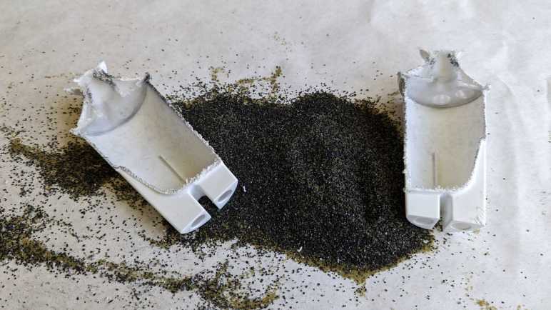
My last teardown got really messy, but that was because I didn’t figure out how to do it right (nondestructively) until the day afterwards. Since I have all of my mess cleanup tools already set up, I decided to tackle projects I had been postponing because I knew they would be messy.
A Brita water filter cartridge is a consumable item to be replaced at regular intervals. From the Wikipedia page for Brita I learned the cartridge contents mostly consisted of “activated carbon” and “ion-exchange resin”.
Some years back, Brita evolved their cartridges to have this inverted-cone shape at the top. This serves as a convenient handle for handling the filter during replacement, but I also understood it had the purpose of diverting the force of water. This filter needs time to do its job, and it is counterproductive to have a stream of tap water force their way directly into the filter. This diverter sends that force sideways.
Given this externally visible mechanism, I started wondering about whether there were any internal mechanisms out of sight. Is this filter just a simple container or are there clever internal baffles to optimize filtering capability? I was also curious if I could see any visible signs of a used filter. I live in an area with hard water where everything that touches water inevitably builds up hard scales. Would I see similar buildup inside a used filter?
When this filter was replaced, I set it aside to dry. I hope it would make things easier to handle and drying would increase the odds of seeing any hard water buildup that might be visible. Once dried, I took a saw and cut it in half. I got the big mess I expected.
This is a closeup of the fine mesh keeping the filter particles out of my drinking water. This is the top mesh, molded from a slightly different textured plastic. There’s also a counterpart bottom mesh. Other than these meshes, there are no internal structures of note inside the filter.
Matching Wikipedia description, I see two different types of material within. I would guess the angular black pieces are activated carbon, and the round translucent yellow-green balls are the ion-exchange resin. And unfortunately, because the action of sawing the cartridge in half created a lot of sawdust from the enclosure’s white plastic, it was not possible to distinguish anything that might be hard water deposit on the filter material.
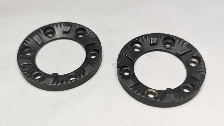
I took apart a retired burr-type coffee grinder and had a hard time because I couldn’t figure out how to take it apart nondestructively. After everything was taken apart, I still was puzzled. While I thought over that problem, I took a closer look at the grinding burrs salvaged from the machine.
I had expected the static burr to be different from the rotating burr, but they appear to be identical parts. Once cleaned up, the only difference was damage visible on the rotating burr. It had been held by rivets that I drilled out and the drill bit scraped off some material. I suppose any optimization for better static vs. rotor performance wouldn’t have been worth the cost of having a different part to manufacturer.
They show minor wear after a few years of use, not nearly as much as I had expected. This material is quite tough standing up to the abuse of grinding coffee beans, far beyond what I can reasonably expect to 3D print. However, I am confident I could design and 3D print some other mechanism to reuse these grinding wheels. I’ll put them in the bin of interesting salvaged parts.
Back to the mystery of the grinder motor: while putting the motor away with other salvaged motors, I noticed strong similarity between the burr grinder motor (right) and the Bodnum chopper grinder motor (left). Their bodies have slightly different diameters and lengths, but show very similar construction techniques. The output shaft and mounting also look very similar.
Once I removed the mounting hardware, the two motors output ends are nearly identical. The only difference I can see is the Bodum motor (left) has a slightly longer threaded length.
With that interesting comparison, I turned both motors around. The motor shaft on the left had a slot so I can use a flat-blade screwdriver to keep the shaft from turning while I unscrew the chopping blade. There was no such visible slot on the right side motor, and that contributed to how my teardown became destructive. For the left side motor, I kept the two screws that mounted the motor to the base. The right side motor had two similar looking screws in identical positions. When I was going around removing every fastener I can find, I somehow overlooked this pair.
Removing all the tail end hardware showed an equally close resemblance between the two motors. While there is no flat slot for a screwdriver, the exposed shaft does have slightly flattened sides so I could grab them with an adjustable wrench. This would have allowed me to keep the motor shaft from rotating as I unscrewed the grinding burr and, from there, take the burr grinder apart nondestructively. This would have been good to find out earlier, now it is too late for the dismembered grinder. I’ll try to keep this lesson in mind for future teardowns.
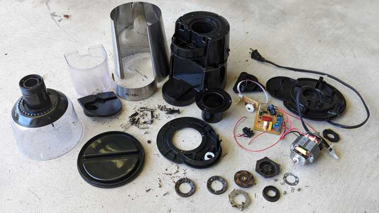
A spinning blade chopping type coffee grinder is a simple concept and can be built very affordably. As a contrast, here’s a more complex and sophisticated burr-type grinder by Mr. Coffee, model BVMC-BMH23.
Instead of a blade swirling through a small amount of beans, a burr-type grinder passes beans between two grinding surfaces. (burrs) This results in a wider adjustable range of grind coarseness and deliver more consistent results. The tradeoff is a more complicated process and that means a more expensive machine.
Hand-cranked coffee grinders are burr style grinders, because a human hand can’t twirl a spinning blade fast enough to chop coffee beans. From that history, one might expect burr-style grinders to work more slowly and quietly, but that expectation was definitely not true of this particular grinder. It is loud. REALLY loud. The previous owner thought it was ridiculous they needed to wear hearing protection to grind their coffee, so when they moved to a different city this machine was left for my teardown pile.
The input hopper is threaded into the machine body. Unscrewing it shows the two burrs covered in dust from all the coffee they’ve ground. Coarseness is dictated by distance between these two grinding surfaces, adjustable via how tightly the intake hopper is screwed into the body.
The nonmoving burr attached to the bottom of the input hopper is held by three screws and comes free easily. I couldn’t take the input hopper any further apart, I believe its plastic components are glued together.
After coffee beans are ground down between the two burrs, resulting bits are ejected out a rectangular port into the output bin.
A simple but effect power cord reel helps keep things neat. There are also five soft silicone feet arrayed around the bottom, each hiding a fastener. The following product information is also stamped on the bottom:
MR.COFFEE
BOCA RATION, FL33431
Coffee Grinder
Model:BVMC-BMH23
120Vac 60Hz 160W
Made in China. Fabrique en Chine
UL LISTED 2358 E130096
After removing the bottom panel, I was surprised to see electrical power wires transitioned from a thick durable household appliance cord to far thinner wires. The neutral wire went to the control circuit board.
The live wire snaked through the device to two safety switches.
One ensures the intake hopper is in place.
The other ensures the output bin is installed.
Removing the three most obvious screws freed the bottom part of the motor mount, but the motor itself is still quite solidly attached. I didn’t see what else is holding it in and the bottom of the motor shaft is not exposed, either. I removed every other fastener I could access from here, but that didn’t release anything.
I had to come back to the top and remove three screws holding this input funnel.
Then the top panel could be freed.
Once the top panel is removed, we can slide off two sheets of metal veneer disguising the plastic nature of this beast.
Top panel controls consisted of a button to start and stop the motor. Surrounding the button is a knob the user could turn to indicate how long to run the motor before it shuts off automatically.
I had expected some sort of integrated button-and-potentiometer unit underneath, like those I found on a car audio head unit to control power & volume. But here is actually a mechanical contraption with separate button and a potentiometer. The control knob is directly over the button for a straightforward connection, but the potentiometer is offset and needed a pair of gears to convey motion. The gear attached to the knob had two sets of “teeth”: one set is actual gear teeth with a sharp profile to convey motion to the potentiometer, the other has a softer rounder profile and that works with a small length of spring steel to give tactile “click” feedback of entirely arbitrary steps in the potentiometer.
This board also had an LED and two resistors. I believe one acts as a current-limiting resistor for the LED and the other a pull-up resistor for the button.
That four-conductor wire leads to the main control board, which had four more connectors: Motor +/- and AC electric power live/neutral.
And… I’m stuck. I saw no more fasteners I could undo, nor do I see any likely hiding places for them. The motor is still securely fastened to the chassis. In the previous two coffee grinder teardowns, the back end of the motor shaft was exposed with a slot where I could insert a flat-blade screwdriver to keep the motor shaft from turning while I unscrewed the chopping blade. In contrast, the back end of this motor has a flat slot, but it’s not the motor shaft and it didn’t help me keep the shaft from turning.
Perhaps fasteners are hidden under this burr? But I don’t see fasteners, those three brass looking components look more like rivets.
I tried drilling them out and, yep, they’re rivets. Freeing the burr and a spinning blade of death beneath it.
But still no fasteners.
Well, this thing is made of plastic, and I know I can cut plastic. I sawed off half of the chassis so I can get a clear side look at the motor mount.
I see hints of four threaded fastneers, but no closer to gaining access to them.
I cut the entire assembly free from the base and still no closer to an answer.
After prying at the grinding wheel for a while, it finally came loose. It was screwed onto the shaft just as the cutting blade did for the earlier coffee grinders.
The motor is finally freed.
Even with the help of hindsight, I’m not sure how I could have disassembled this nondestructively. I would need a method to keep the motor shaft from turning while I unscrewed the grinding wheel. (Drilling out the rivets were an unnecessary detour.) But I still don’t see how I could have accomplished that.


